18650 Discharger
A self powered 18650 Lithium-Ion battery discharge board.
A self powered 18650 Lithium-Ion battery discharge board.
To make the experience fit your profile, pick a username and tell us what interests you.
We found and based on your interests.
badito_V5_BOM.xlsxBill of Materialssheet - 9.28 kB - 01/28/2021 at 19:55 |
|
|
badito_V5.zipGeber files 18650 discharger V5x-zip-compressed - 101.41 kB - 01/28/2021 at 19:43 |
|
|
badito_V5.schEagle schematic design file 18650 discharger V5sch - 108.67 kB - 01/28/2021 at 19:42 |
|
|
badito_V5.brdEagle layout design file 18650 discharger V5brd - 38.24 kB - 01/28/2021 at 19:42 |
|
I had a genious thought. These Li-ion protection boards are about 0.14 euro,
while there are also these 0.17 euro TP4056 1A Li-ion chargers including the protection circuit, which I had still lying around.
So I quickly hooked it up and tested it
And it works well. Then I designed a new PCB and ordered from JLCPCB and soldered it.
Now I feel happy
So I have designed a new board and added JP2, which could be used to connect a charger.
I have received the new PCBs and soldered the protection module.
I made a smoll mistake. JP2 is for connecting a battery charger but I accidently swapped the labels P- and B+ in silkscreen.
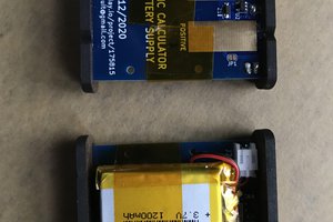
A fully assembled board looks like this
Here's a video
It works great. The 2.5 Ohms load is disconnected at 2.54V and reconnects at 2.87V. The power resistors get hot not dangerously hot, current is about 1.5A which is a safe 0.5C discharge rate for 18650 Li-ion cells. After the battery was discharged to 2.54V the voltage recovered to about 2.85V, which is great. The protection module it self takes about 3uA in normal voltage range and about 0.9uA below 2.54V, which is great. Total BOM cost is 1.70 euro in quantities of 10. I think now it is time to start selling them on Tindie.
I have redesigned the board. I added a momentary tactile switch between GND and CS pin, to reset the DW01 IC after a undervoltage lockout. In addition I have added two battery connectors, one JST PH that will connect to many Li-Po batteries, and a 2p header at 2.54mm pitch. Finally I made a hole in the PCB for pushing out the battery from bottom.
The boards were ordered from JLCPCB.
The components I ordered from LCSC.com and tested DW01+G and DW01A-G. According to the datasheet the last one should have auto recovery, which means that after a overdischarge the chip goes back into normal operation when the battery voltage exceeds 3.0V. I expected to measure 0.1 or 1.5uA shut down current (when vbat is <2.4V) but I measured 20uA current and when the load was connected I measured 2400uA (exactly 2.4V/1kohm). Then I found I made a silly mistake in the design
I wired the tactile switch such that it is always connected. Then I removed the switch completely and continued testing. I noticed with DW01+G the circuit was working fine, it was low power, and it does not have auto recovery as expected, but it recovered after the tactile switch was pressed, which you may forget. The DW01A-G should have auto recovery but it didn't work and I don't understand why. Only after pressing the tactile switch it recovered, but this is not very handy. I want this circuit to automatically work and not require manual action.
Then I remembered I still had a bunch of $0.15 18650 3A protection boards, like this one.
I hooked it up
And then it worked as expected, after a overdischarge (<2.4V) it disconnected the load and battery voltage could rise again untill it exceeds the re-enable voltage and the protection IC was back in normal mode . I measured 2.3uA in normal operation and 0.9uA in overdischarge state which is great. Zooming into the chips shows that it actually uses the DW01-A
Ok so now the circuit is working as expected and I need to design a new PCB using above protection board.
I designed V4 of the board with the battery protection boards as a module and immediately ordered from JLCPCB.
In version 1 of the board I used a comparator to disable the discharge, but now I have simplified the design. It uses a cheap battery protection circuit as the basis. You may find these Li-ion protection modules aliexpress for $0.15 each.
They have DW01 protection IC and the FS8205A dual N-channel mosfet both from Fortune Semiconductor. I have designed this circuit in components so I could replace DW01 which has 2.40V undervoltage level with another IC with higher undervoltage level like the FS312 which is at 2.90V.
I have ordered the PCBs from Elecrow and I expect they arrive 22 May 2020. Components were ordered from Aliexpress.
I have just received the boards and assembled two of them. One is equiped with the DW01+G and another with the DW01A-G.
It seems to work. The LED turns on and the resistors get hot, too hot to touch, so in the next design I reduce the discharge current from 1C (~3A) to 0.5C (~1.5A).
DW01A-G discharged until 2.40V and when voltage exceeded 3.00V it started discharging again in an endless loop, because it has "standby function release". When discharging is terminated this IC continued to use 1.5uA current from the battery.
DW01+G discharged until 2.40V and then it went into 0.1uA power down mode. It never reconnected the load even when battery voltage exceeded the re-enable voltage of 3V. This IC does not have "standy function release", it has a sort of one-shot protection. It can be restored to normal operation by shorting the CS pin to GND (or by connecting a charger), so in next design I need to add a momentary switch there. After the load was disconnected the battery regained voltage to slightly above 3.00V, which is perfect because most battery chargers will start the fast charging above 3.0V.
I also learned the batteries are not easy to remove from the holders and you need a string to remove them.
In near future I wan to test with FS312F-G that disconnects the load at 2.9V, and it will recover to a voltage much higher than 3.00V, like 3.3V or something.
I named the board BaDiTo after Battery Discharge tool. The first version of the board basically consist of power resistors, a mosfet and a comparator and a LED. Using one rocker switch you can choose between 1.5A load (2 resistors in parallel) or 3A load (4 resistors in parallel) which equals about 0.5C and 1C discharge current. The other rocker switch is to choose between two discharge voltages, 3.5V or 3.0V. The LED is on during discharging and it goes off when the dicharge voltage is reached. I have selected a low power comparator (TLV7011) and used a 2.5V LDO to make a stable reference votage. The PCB was just 4.90 USD and components about 2 USD.
When I received the boards I was happy. Elecrow did a great job.
When I tested the board it didn't work well. BaDiTo V1 FAILED. The discharge current was lower than expected and when connected to a oscilloscope I found oscillation. I realised I made a stupid mistake. The comparator should have been designed with a large hysteresis. When the voltage falls below the threshold, the load is removed, the voltage jumps back up and the load is re-enabled, then the voltage falls again and the load is removed, etc. in an endless loop, which is oscillation.
Then I remebered this board https://easyeda.com/Iam1CM69/18650-discharge-board designed by https://twitter.com/AstroTogger
Create an account to leave a comment. Already have an account? Log In.
Check out FS312 if you're interested in a battery protection IC with a 3.0V cutoff, it's by the same company that made DW01 and it has the same package & pinout.
In version 2 of the board I have designed the protection circuit in components so I can replace DW01 with FS312. I will test it out.
You have those ICs? I can mail you 5pcs if you DM me your address.
I'm from Europe, so you will get them quickly.
I've got a flashlight that runs on a single 18650 - wonder if I should build something like this to more fully discharge the battery before throwing it on the charger?
I believe Li-ions don't have memory effect so there is no need to discharge before charging
Become a member to follow this project and never miss any updates
By using our website and services, you expressly agree to the placement of our performance, functionality, and advertising cookies. Learn More

 tomcircuit

 Frank Adams
Nice one, but the problem is that LCSC delivery in australia are getting worst, therefore i have to order from X-on Electronics.
https://www.x-on.com.au