 Frank
Frank-
11. Peripherals Setup: DS3231 RTC
The first and easiest device to test and integrate is the DS3231 realtime clock.
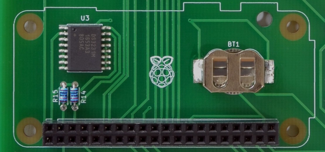
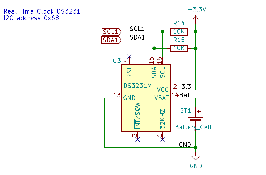
To save PCB space, I placed the RTC IC, the backup battery holder, and the I2C pull-up resistors underneath the Raspberry Pi Zero W.
![]()
I wasn't sure, but all Raspberry Pi versions are said to be fitted with I2C pull-up resistors. For the first "Alpha" board I added the pull-up pair (R14,R15) to the footprint, and populated them with 10K. When I got the Pi Zero later, I could clearly see the tiny pull-ups, they are placed next to the GPIO pins. This means I wont need external pull-ups. For now I use R14/R15 as hook-up points to the oscilloscope, and remove them from further revisions. The RPi built-in 1.8K resistance is quite strong, and should be more than enough.
![]()
After the first RPi boot with a pristine Raspbian lite image, I am running raspi-config to enable I2C, SPI, SSH; and to configure the network access for further package downloads. The DS3231 RTC already has kernel support, and technically we don't need to download anything. However I want to run tests to verify the I2C function before I change the system. Since I also need git, the next step is downloading git together with the I2C packages.
pi@rpi0w:~ $ sudo apt-get install git i2c-tools libi2c-dev

pi@rpi0w:~ $ git clone https://github.com/fm4dd/picon-one-sw.git
Running 'i2cdetect' returns two devices. 0x48 is the serial expander IC, and 0x68 is the RTC.
pi@rpi0w:~ $ i2cdetect -y 1
     0  1  2  3  4  5  6  7  8  9  a  b  c  d  e  f
00:          -- -- -- -- -- -- -- -- -- -- -- -- --
10: -- -- -- -- -- -- -- -- -- -- -- -- -- -- -- --
20: -- -- -- -- -- -- -- -- -- -- -- -- -- -- -- --
30: -- -- -- -- -- -- -- -- -- -- -- -- -- -- -- --
40: -- -- -- -- -- -- -- -- 48 -- -- -- -- -- -- --
50: -- -- -- -- -- -- -- -- -- -- -- -- -- -- -- --
60: -- -- -- -- -- -- -- -- 68 -- -- -- -- -- -- --
70: -- -- -- -- -- -- -- --
Now changing into the cloned 'picon-one-sw' directory, there is a folder 'src/rtc-ds3231' with a small 'C' test program to compile. This program tries to read from the RTC, and returns its time.
pi@rpi0w:~ $ cd picon-one-sw/src/rtc-ds3231/

pi@rpi0w:~/picon-one-sw/src/rtc-ds3231 $ make
gcc -Wall -g -O1    test-ds3231.c   -o test-ds3231

pi@rpi0w:~/picon-one-sw/src/rtc-ds3231 $ ./test-ds3231
DS3231 DATE: Tuesday 2020-06-02 TIME: 00:36:16
With the clock operational, I finally enable the kernel driver hardware overlay in '/boot/config.txt'.
pi@rpi0w:~ $ sudo su
root@rpi0w:/home/pi# echo "dtoverlay=i2c-rtc,ds3231" >> /boot/config.txt

root@rpi0w:/home/pi# tail -2 /boot/config.txt
enable_uart=1
dtoverlay=i2c-rtc,ds3231

root@rpi0w:/home/pi# reboot
After the reboot, the new /dev/rtc0 device will become available, lsmod lists the loaded kernel module, and i2cdetect -y 1 now returns 'UU' to show the device is used by a driver.
pi@rpi0w:~ $ dmesg |grep rtc
[   22.531026] rtc-ds1307 1-0068: registered as rtc0

pi@rpi0w:~ $ lsmod |grep rtc
rtc_ds1307             24576  0
hwmon                  16384  2 rtc_ds1307,raspberrypi_hwmon

pi@rpi0w:~ $ i2cdetect -y 1 |grep 60
60: -- -- -- -- -- -- -- -- UU -- -- -- -- -- -- --
Lastly, there is one more step to edit '/lib/udev/hwclock-set'.
Here are two excellent articles that cover the Raspberry Pi RTC setup in more detail:
https://www.raspberrypi.org/forums/viewtopic.php?t=161133
https://learn.adafruit.com/adding-a-real-time-clock-to-raspberry-pi/set-rtc-time
Do you know an even better RTC? With even higher accuracy, more functions, simpler to use, or smaller footprint? Feel free to leave a comment, I would appreciate. Cheers! Frank
-
22. Peripherals Setup: 7-Segment Display Control
For prominent data, or data tat is fast changing, the dual 7-segment displays bring numbers to attention just by casual glance.
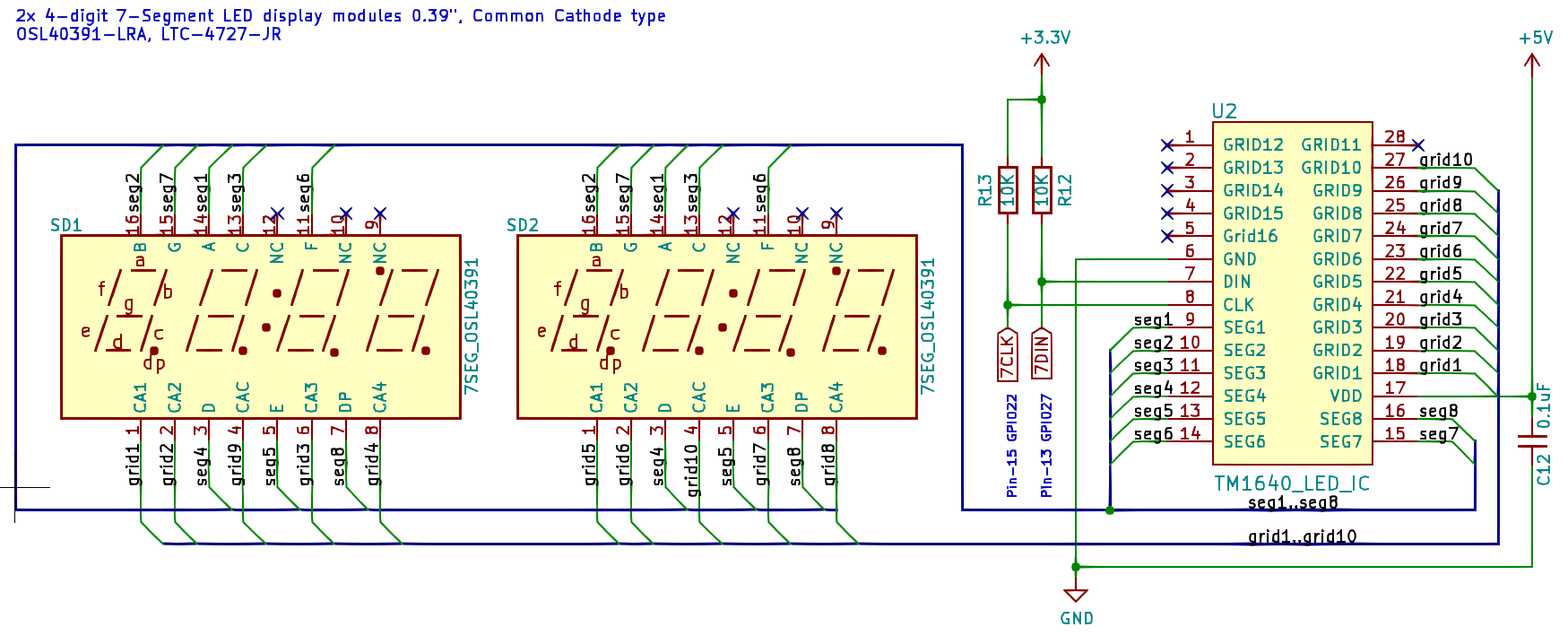
To drive the display LEDs, I selected the TM1640 LED driver IC from Titan Micro Electronics. Because the IC is only available in a surface mount (SMT) package, I couldn't test it beforehand (e.g. on a breadboard). This is a general challenge with SMT circuits. Either a separate evaluation kit is needed for reference, or we take a leap of faith: Implementing new IC "blind" with an expectation that it is going to work out. The TM1640 is an attractive IC because it eliminates the need for current limit resistors on each LED segment. This greatly simplifies the setup, and this IC allows control of up to 16 digits. As a small drawback, the IC only runs on 5V, and requires "common cathode" type displays. There is a way of adopting "common anode" modules, but that requires swapping segment with grid lines (confusing), requires attention on the driver side, and reduces the usable digits count as well.
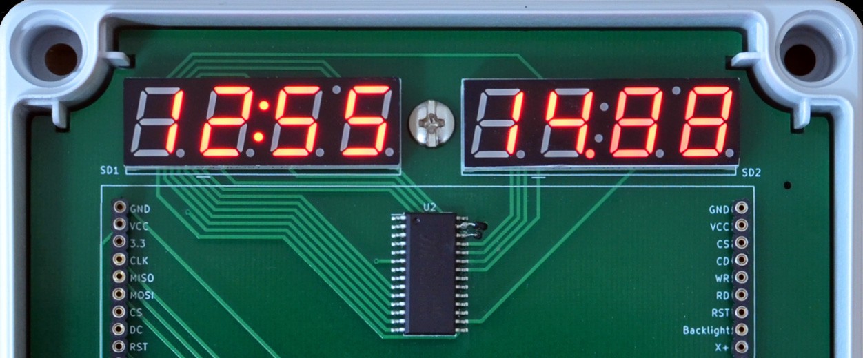
With the "leap-of-faith" method, I wasn't sure if I could get the extra colon and degree LEDs of the 7-segment module to work. During PCB design, I only connected the digit grid lines, and left the extra LED grid unconnected. I regretted this decision immediately after I started to work with the IC. For one, it is really helpful to display time with the conventional blinking colon. Once I read the driver code, I could also see how to implement the support for it. So I decided to drill two small holes, and hand-solder the missing wires to the IC. TM16040 LED display driver, with the extra grid lines hand-wired:
![]()
This improvisation is fun while working with a fresh design. Below is the updated schematic, already including the two hand-wired lines for "grid-9" and "grid-10" signals.
![]()
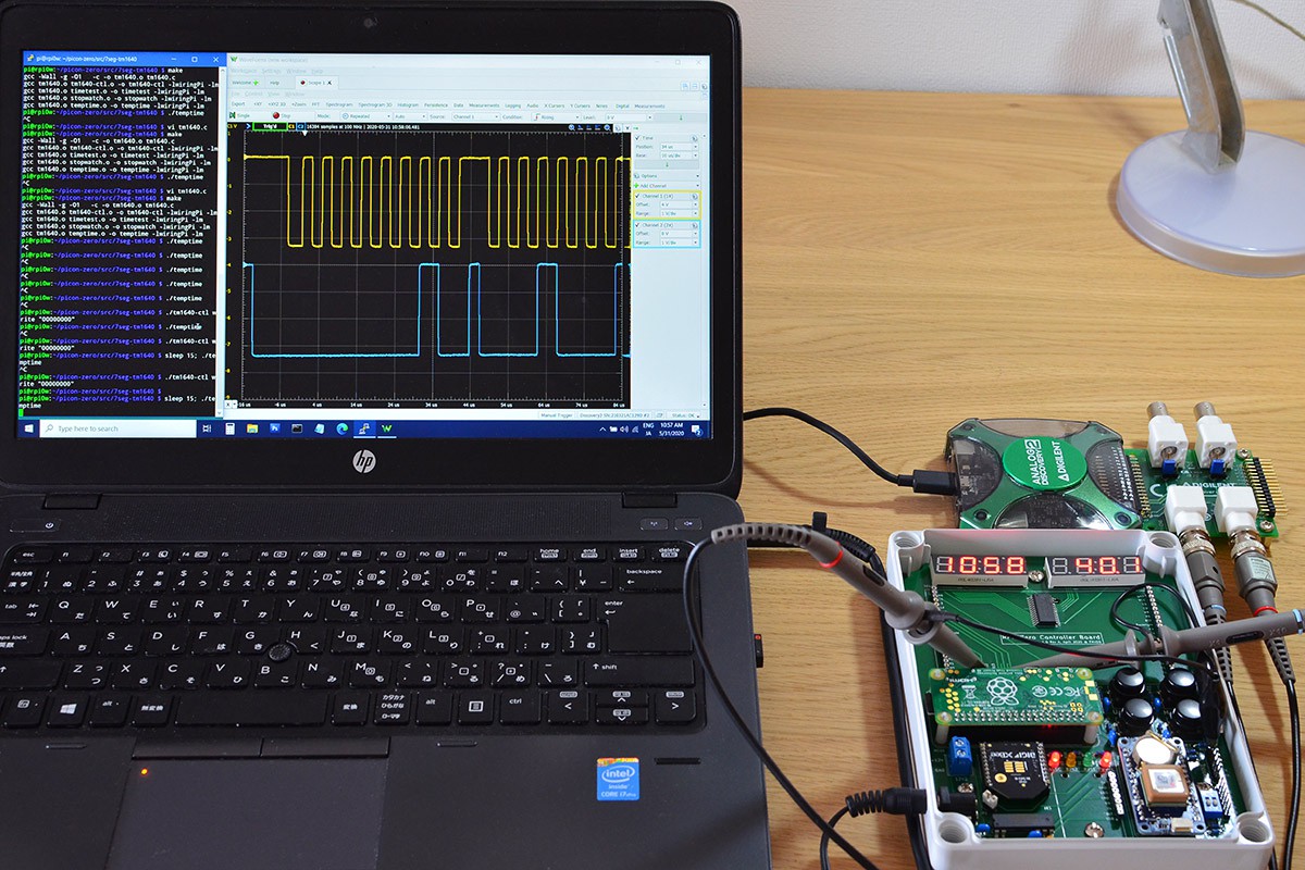
The IC uses a proprietary 2-wire serial protocol that has similarities to I2C. It implements a bus clock line, and the data line to transmit four signal types. Three are command bytes 1..3, plus the data bytes that carry the segment encoding for a digit. The instructions need to be send in sequence, and some require specific start-end signaling. This is difficult to code without verification. An oscilloscope such as the Digilent Analog Discovery 2 is invaluable here.
![]()
Michael Farrell wrote the Raspberry Pi driver code for TM1640, which is available at his Github repository. His code is published under GPLv3, and he deserves all the credit. The driver code is very small, it needs only 3 source files for programming under 'C'.
Since I don't need a dedicated library, I just link the driver files into the control programs with minimal overhead. For tests I created below example programs:
1.) timetest
This program shows the current time on all eight digits: hour, min, seconds, and two-digit sub-seconds. It demonstrates the responsiveness of apps under RPi Linux.
2.) temptime
This program shows the current time in HH:MM on the first (left) display, and the CPU temperature on the second (right) display. This program is helpful to monitor how the controller heat develops inside the case when the protective lid is closed.
3.) stopwatch
This example implements a simple stopwatch, showing the elapsed time over all eight digits. It is controlled by three push-buttons: "Mode" starts or restarts the clock, "Enter" stops the clock, and "Up" resets the clock to zero.
4. tm1640-ctl
This is the display control program from the original driver, with an added -ctl.
pi@rpi0w:~/picon-zero/src/7seg-tm1640$ ./tm1640-ctl
TM1640 display tool
Usage:
  tm1640-ctl on <0..7>  : Turn on and set brightness. 1 (lowest)..7 (highest)
  tm1640-ctl off        : Turn off display, preserving data.
  tm1640-ctl clear      : Clear display.
  tm1640-ctl write <num>: Write digits to display, up to 8 digits.
These programs are in the software repo under src/7seg-tm1640:
pi@rpi0w:~ $ cd picon-one-sw/src/7seg-tm1640/

pi@rpi0w:~/picon-one-sw/src/7seg-tm1640 $ make
gcc -Wall -g -O1   -c -o tm1640.o tm1640.c
gcc -Wall -g -O1   -c -o tm1640-ctl.o tm1640-ctl.c
gcc tm1640.o tm1640-ctl.o -o tm1640-ctl -lwiringPi -lm
gcc -Wall -g -O1   -c -o timetest.o timetest.c
gcc tm1640.o timetest.o -o timetest -lwiringPi -lm
gcc -Wall -g -O1   -c -o stopwatch.o stopwatch.c
gcc tm1640.o stopwatch.o -o stopwatch -lwiringPi -lm
gcc -Wall -g -O1   -c -o temptime.o temptime.c
gcc tm1640.o temptime.o -o temptime -lwiringPi -lm

pi@rpi0w:~/picon-one-sw/src/7seg-tm1640 $ ./temptime
Until I have a final display requirement, I initialize the 7-Segment displays with the 'temptime' program at boot time in /etc/rc.local.
While it is running, I can adjust the brightness, and dimm it down with 'tm1640-ctl on 2' if needed.
The initial gamble on implementing the TM140 IC paid off. The display works great, including control over the extra colon and degree LEDs.
-
33. Peripherals Setup: TFT Display Control
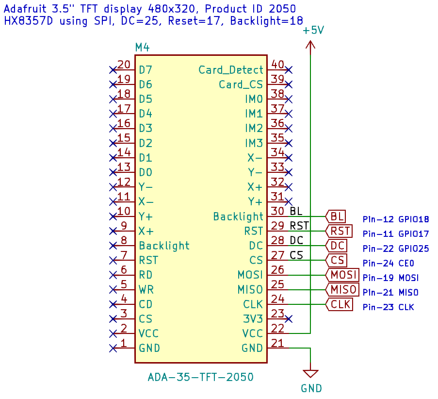
This step describes the TFT display setup for PiCon One. The TFT display I am using is the Adafruit 3.5 480x320 display with product ID 2050.
The current pin assignment for this TFT on PiCon One v1.0a is matching the Adafruit 3.5 PiTFT (product ID 2097). This allows to use original Adafruit drivers, and to follow Adafruit documentation. The TFT screen itself is identical for both product IDs 2050 and 2097, the pin layout is different.
![]()
The choice for the 2050 display comes from the single-row pin location, non-populated. This allows to select low-profile connector that reduces the stand-off height by 3mm.
Get framebuffer driver code and pre-requisites
I choose the 'juj' SPI TFT driver over Adafruits original. Two specifics make it attractive: Great performance, and its design as a "standalone" binary driver. The driver creates the /dev/fb0 device, eliminating the need to mirror framebuffers.
pi@rpi0w:~ $ git clone https://github.com/juj/fbcp-ili9341.git
Cloning into 'fbcp-ili9341'...
The compiler configuration of this driver requires 'cmake'.
pi@rpi0w:~ $ sudo apt-get install cmake
Configure framebuffer compile options
Now the driver settings need to be specified for TFT hardware and pin configuration:
pi@rpi0w:~/fbcp-ili9341 $ cmake -DSPI_BUS_CLOCK_DIVISOR=8 -DHX8357D=ON\
-DADAFRUIT_HX8357D_PITFT=ON -DGPIO_TFT_DATA_CONTROL=25\
-DGPIO_TFT_RESET_PIN=17 -DGPIO_TFT_BACKLIGHT=18\
-DSINGLE_CORE_BOARD=ON -DARMV6Z=ON -DSTATISTICS=0\
-DDISPLAY_ROTATE_180_DEGREES=ON -S .
-- Doing a Release build
-- Board revision: 9000c1
-- Detected this Pi to be one of: Pi A, A+, B rev. 1, B rev. 2, B+, CM1, Zero or Zero W, with single hardware core and ARMv6Z instruction set CPU.
-- Targeting a Raspberry Pi with only one hardware core
-- Enabling optimization flags that target ARMv6Z instruction set (Pi Model A, Pi Model B, Compute Module 1, Pi Zero/Zero W)
-- Using 4-wire SPI mode of communication, with GPIO pin 25 for Data/Control line
-- Using GPIO pin 17 for Reset line
-- Using GPIO pin 18 for backlight
-- Scaling source image to view. ...
-- Preserving aspect ratio when scaling ...
-- SPI_BUS_CLOCK_DIVISOR set to 8. ...
-- Rotating display output by 180 degrees
-- USE_DMA_TRANSFERS enabled ...
-- Targeting Adafruit 3.5 inch PiTFT with HX8357D
-- Configuring done
-- Generating done
-- Build files have been written to: /home/pi/fbcp-ili9341
Compile the framebuffer driver
pi@rpi0w:~/fbcp-ili9341 $ make
Scanning dependencies of target fbcp-ili9341
[  5%] Building CXX object CMakeFiles/fbcp-ili9341.dir/diff.cpp.o
...
[ 95%] Building CXX object CMakeFiles/fbcp-ili9341.dir/text.cpp.o
[100%] Linking CXX executable fbcp-ili9341
[100%] Built target fbcp-ili9341
Lets check the created driver program:
pi@rpi0w:~/fbcp-ili9341 $ ls -l fbcp-ili9341
-rwxr-xr-x 1 pi pi 65304 Jun  5 05:39 fbcp-ili9341

pi@rpi0w:~/fbcp-ili9341 $ file fbcp-ili9341
fbcp-ili9341: ELF 32-bit LSB executable, ARM, EABI5 version 1 (SYSV), dynamically linked, interpreter /lib/ld-linux-armhf.so.3, for GNU/Linux 3.2.0, BuildID[sha1]=d2fc883388c782d08b7565f1ae22c95466928b66, with debug_info, not stripped
Test the framebuffer driver
Now we can start the framebuffer driver. It should initialize the display and show console output on the screen.
pi@rpi0w:~/fbcp-ili9341 $ sudo ./fbcp-ili9341 &
[1] 2101
pi@rpi0w:~/fbcp-ili9341 $ bcm_host_get_peripheral_address: 0x20000000, bcm_host_get_peripheral_size: 33554432, bcm_host_get_sdram_address: 0x40000000
BCM core speed: current: 250000000hz, max turbo: 250000000hz. SPI CDIV: 8, SPI max frequency: 31250000hz
Allocated DMA channel 7
Allocated DMA channel 1
Enabling DMA channels Tx:7 and Rx:1
DMA hardware register file is at ptr: 0xb4afc000, using DMA TX channel: 7 and DMA RX channel: 1
DMA hardware TX channel register file is at ptr: 0xb4afc700, DMA RX channel register file is at ptr: 0xb4afc100
Resetting DMA channels for use
DMA all set up
Initializing display
Resetting display at reset GPIO pin 17
InitSPI done
Relevant source display area size with overscan cropped away: 720x480.
Source GPU display is 720x480. Output SPI display is 480x320 with a drawable area of 480x320. Applying scaling factor horiz=0.67x & vert=0.67x, xOffset: 0, yOffset: 0, scaledWidth: 480, scaledHeight: 320
Creating dispmanX resource of size 480x320 (aspect ratio=1.500000).
GPU grab rectangle is offset x=0,y=0, size w=480xh=320, aspect ratio=1.500000
All initialized, now running main loop...
Next I write a test image to it, using the fbi command. The test image 480x320-test.jpg is located under picon-one-sw/src/tft-hx8357d/images. This test needs the fbi program.
pi@rpi0w:~ $ sudo apt-get install fbi
...
Need to get 17.1 MB of archives.
After this operation, 56.2 MB of additional disk space will be used.
Now we can run:
pi@rpi0w:~ $ sudo fbi -t 60 -cachemem 0 --autozoom --noverbose -d /dev/fb0 --vt 1 picon-one-sw/src/tft-hx8357d/images/480x320-test.jpg
using "DejaVu Sans Mono-16", pixelsize=16.67 file=/usr/share/fonts/truetype/dejavu/DejaVuSansMono.ttf
![]()
TFT test image display with 'fbi' Framebuffer driver auto-start
Adjust console font to 6x12 version. This is helpful to fit the common console size of 80x23chars into the screen.
pi@rpi0w:~ $ sudo vi /etc/default/console-setup
CHARMAP="UTF-8"

CODESET="guess"
FONTFACE="Terminus"
FONTSIZE="6x12"
Set HDMI display options in /boot/config.txt
pi@rpi0w:~ $ vi /boot/config.txt
framebuffer_heigth=320
framebuffer_width=480
hdmi_force_hotplug=1
hdmi_cvt=480 320 60 1 0 0 0
hdmi_group=2
hdmi_mode=87
For more information on above display settings, see
https://www.raspberrypi.org/documentation/configuration/config-txt/video.mdRunninng the driver at startup:
pi@rpi0w:~ $ vi /etc/rc.local
sudo /home/pi/fbcp-ili9341/fbcp-ili9341 &
The console idle function may turn off the display backlight.
The next line attempts to prevent that.pi@rpi0w:~ $ vi /etc/rc.local sudo sh -c "TERM=linux setterm -blank 0 >/dev/tty1"
-
44. Peripherals Setup: Dual UART expander SC16IS752
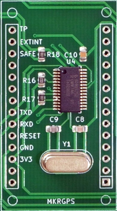
To extend the serial ports on the Raspberry Pi Zero, PiCon One has been fitted with the dual UART expander IC SC16IS752 from NXP. On the PCB, the expander IC has been placed underneath the connectors for the SAM-M8Q MKRGPSShield module:
![]()
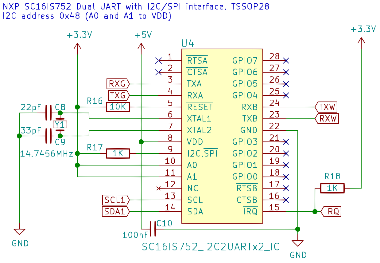
Below is the schema that shows how the IC connects to the RPi:
![]()
Thanks to the existence of an hardware overlay, enabling the ports under Raspberry Pi Linux only requires to add one line into /boot/config.txt:
pi@rpi0w:~ $ sudo vi /boot/config.txt
dtoverlay=sc16is752-i2c,int_pin=24,addr=0x48
After next boot, we got two new serial devices: /dev/ttySC0 and /dev/ttySC1:
:pi@rpi0w:~ $  ls -l /dev/ttyS* /dev/ttyAMA*
crw--w---- 1 root tty     204, 64 Jun  7 14:19 /dev/ttyAMA0
crw-rw---- 1 root dialout   4, 64 Jun  6 13:26 /dev/ttyS0
crw-rw---- 1 root dialout 239,  0 Jun  7 14:38 /dev/ttySC0
crw-rw---- 1 root dialout 239,  1 Jun  6 13:26 /dev/ttySC1
The serial ports connect to the module sockets for the GPS receiver module (RXG,TXG = /dev/ttySC0), and the XBee module (RXW,TXW = /dev/ttySC1). The ports are also connected to pin header J2 for external access.
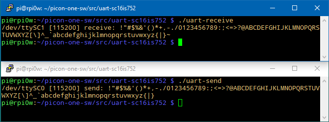
Two programs are available under picon-one-sw/src/uart-sc16is752.
By cross-connecting TXA to RXB, and TXB to RXA on pin header J2, the serial communication can be verified while no module is installed yet.
![]()
-
55. Peripherals Setup: XBee radio transmission module
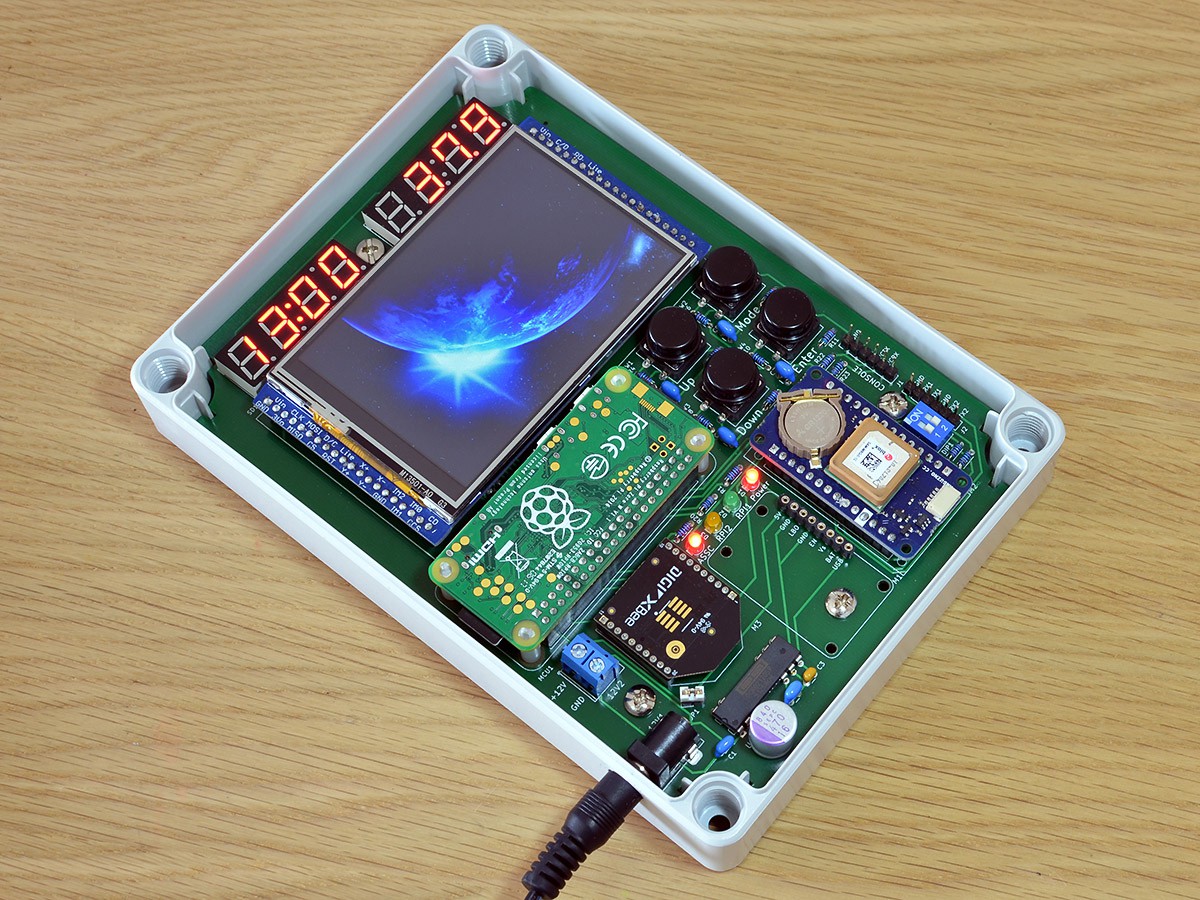
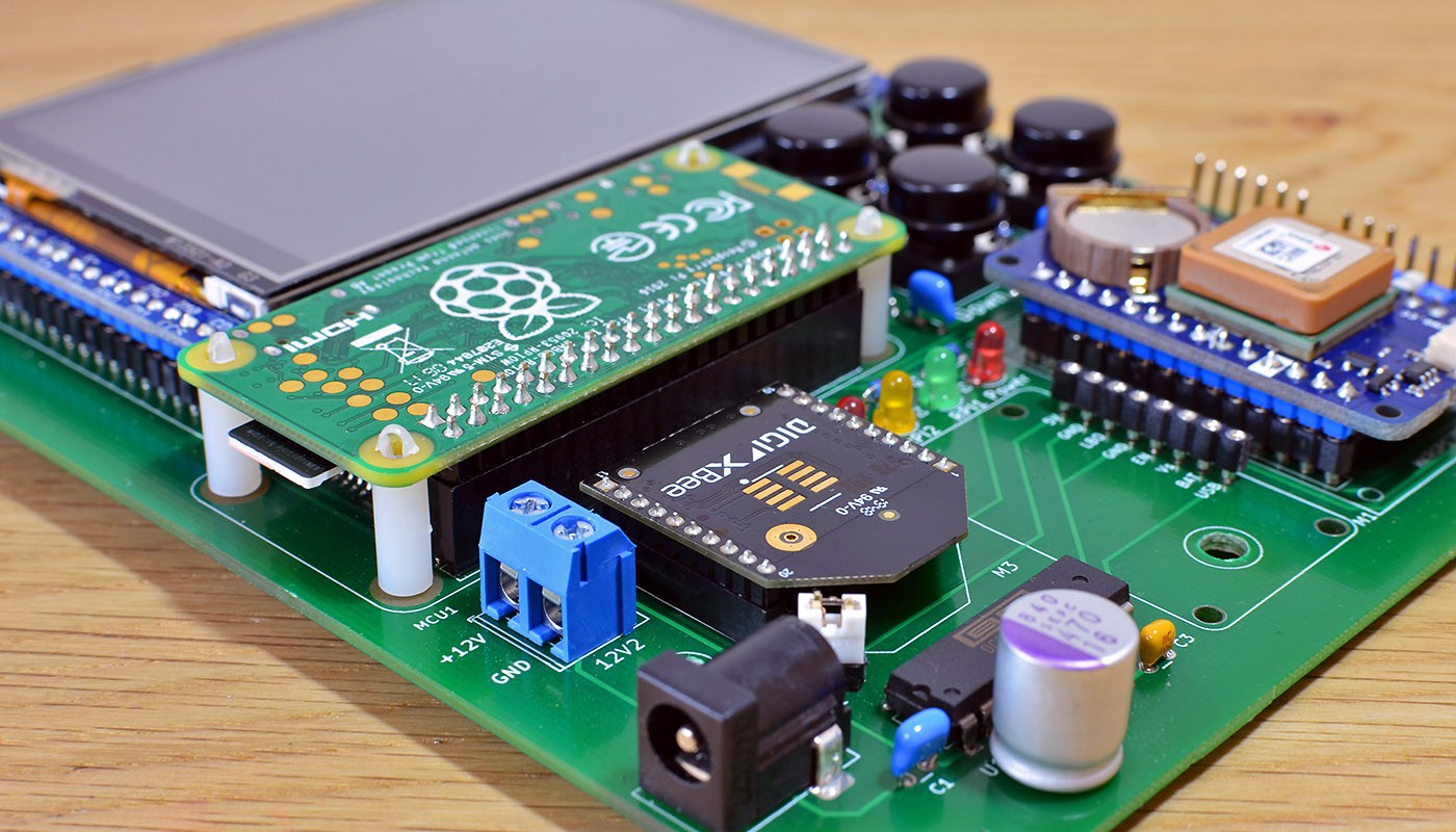
In addition to the Raspberry Pi's Wifi network, PiCon One can connect a Digi XBee radio transmission module. I am using the XBee/Zigbee in transparent mode to let the controller broadcast control information to a group of MCU's.
![]()
XBee 3 radio module installed on PiCon One On PiCon One, the XBee module connects to port B of the serial expander IC SC16IS752. This means under Linux, the XBee communication device is /dev/ttySC1.
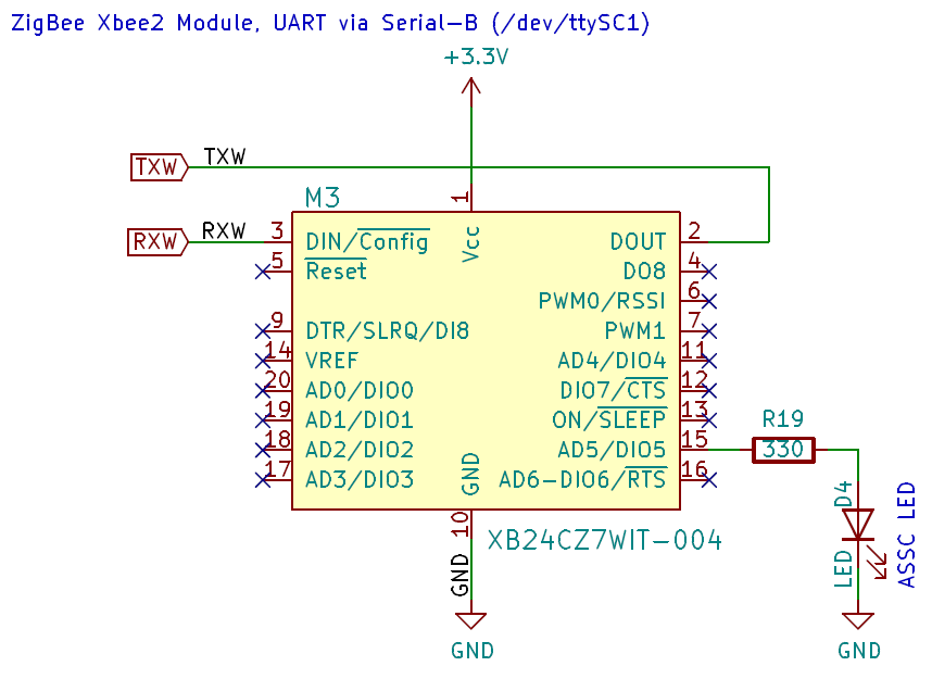
![]()
Above is the schema for the XBee module connectivity. PiCon One has the ASSOC LED wired to DIO-5, showing the current
network association status through its pulse frequency.
I on the MCU-side I am using XBee S2C modules, and I am going to test by adding the XBee 3 as the network coordinator into the mix.For a simple device verification in Linux, the program 'xbee-test' is located under
picon-one-sw/src/uart-sc16is752. This program opens the serial port,
sends the command mode sequence, and confirms the XBee responds to an exemplary AT command.pi@rpi0w:~/picon-one-sw/src/uart-sc16is752 $ ./xbee-test XBee DEV open: /dev/ttySC1 115200B XBee CMD mode: OK Xbee cmd ATSL: [41B7962A]
As an alternative, the minicom program could also be used (after installation).
pi@rpi0w:~ $ minicom -D /dev/ttySC1
+++OK

CTRL-A Z for help | 9600 8N1 | NOR | Minicom 2.7.1 | VT102 | Offline | ttySC1
pi@rpi0w:~ $
While Digi provides the XBee configuration program XCTU for Linux,
it also has a code library for C. I am writing a set of basic routines to read XBee status, set configuration options, and to exchange control data messages. This code should appear
under picon-one-sw/src/xbee-module, once it becomes sufficiently mature to share.
XBee getinfo
Debug: /dev/ttySC1 send +++
Debug: /dev/ttySC1 got 3 bytes after 1100 ms
Debug: port /dev/ttySC1 reply: OK (2 bytes)
Debug: XBee CMD mode start complete.
Debug: send CMD ATVR
Debug: got 5 bytes after 100 ms
Debug: reply 100A (4 bytes)
Debug: send CMD ATHV
Debug: got 5 bytes after 100 ms
Debug: reply 424C (4 bytes)
Debug: send CMD ATNI
Debug: got 10 bytes after 100 ms
Debug: reply PiCon-One (9 bytes)
Debug: send CMD ATSH
Debug: got 7 bytes after 100 ms
Debug: reply 13A200 (6 bytes)
Debug: MAC 0013A200
Debug: send CMD ATSL
Debug: got 9 bytes after 100 ms
Debug: reply 41B7962A (8 bytes)
Debug: MAC 0013A20041B7962A
Debug: send CMD AT%V
Debug: got 4 bytes after 100 ms
Debug: reply D0B (3 bytes)
Debug: Convert Volt: 3.339
Debug: /dev/ttySC1 send ATCN\r
Debug: /dev/ttySC1 got 3 bytes after 100 ms
Debug: port /dev/ttySC1 reply: OK (2 bytes)
Debug: XBee CMD mode finished.
PiCon One
PiCon One is a multi-function controller for home automation and industrial use cases.
Discussions
Become a Hackaday.io Member
Create an account to leave a comment. Already have an account? Log In.