Frank
Frank-
XBee Serial Communications
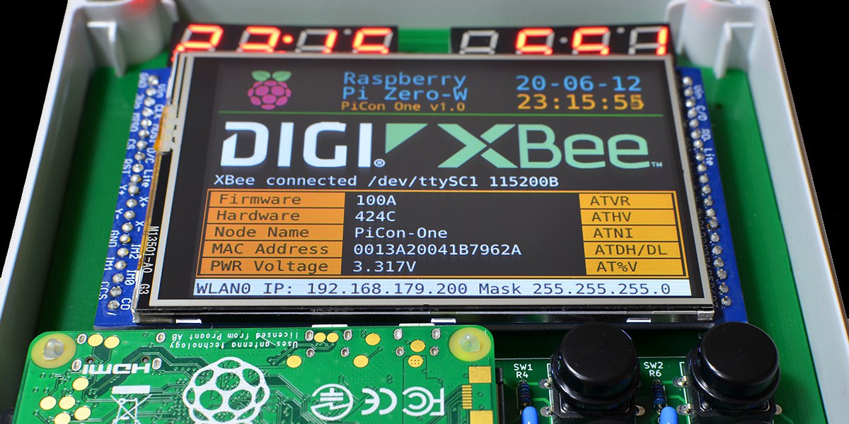
06/12/2020 at 14:06 • 0 commentsWith the latest update to the setup instructions, the XBee module is coming into life. While there is always more work to do, here is a picture showing progress.
![]()
XBee3 reporting for duty on PiCon One -
JPL Horizon Solar Positioning Data Aquisition
06/09/2020 at 14:49 • 0 commentsSince 2019 I work on motorizing solar PV panels, to let them track the sun. Because our sun is an extremely bright object, one method is self-orientation with directional light-sensors. Another approach is to calculate the suns position, based on the known mechanics of our planet and solar system.
Last year I have been working with NREL's solar position algorithm, writing the 'suncalc' program to create solar position datasets for suntrackers. Unfortunately, the SPA code from the US Department of Energy is not freely accessible. It is not Open Source, which hinders easy adoption and code sharing.
Thanks to the great community at Hackaday, @RichardCollins commented on the earlier project, and pointed me towards the JPL Horizon system. Richard, thanks for taking the time! It's these encouragements that lead to this years PiCon One project.
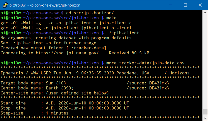
JPL Horizon is an online solar system computation service for all kinds of celestial objects. And YES it works! I can just send a query to Horizon, which then returns the suns dataset specific for my geographic location. An example query for solar position azimuth and elevation data looks like this:
curl "https://ssd.jpl.nasa.gov/horizons_batch.cgi?batch=1&COMMAND='10'&CENTER='coord@399'&COORD_TYPE='GEODETIC'&SITE_COORD='139.628999,35.610381,0.005'&MAKE_EPHEM='YES'&TABLE_TYPE='OBSERVER'&START_TIME='2020-06-09'&STOP_TIME='2020-06-10'&STEP_SIZE='1 m'&QUANTITIES='4'&APPARENT='REFRACTED'&CSV_FORMAT='YES'&OBJ_DATA='NO'" > 20200609-jplh.csv
  % Total    % Received % Xferd  Average Speed   Time    Time     Time  Current
                                 Dload  Upload   Total   Spent    Left  Speed
100 82264    0 82264    0     0  42935      0 --:--:--  0:00:01 --:--:-- 42912
The returned data is exactly what I hoped for. I am now working on a client program "jplh-client" that periodically fetches the data, with latest coordinates fresh from the GPS.
![]()
Still in early stages: solar position client program to JPL Horizon If by chance someone from JPL is reading: Big Thanks to the team at Pasadena Jet Propulsion Laboratory for running the service.
-
TFT Display Tests
06/06/2020 at 05:16 • 0 commentsFor working with the TFT display, I created two sample applications in the GitHub software repository:
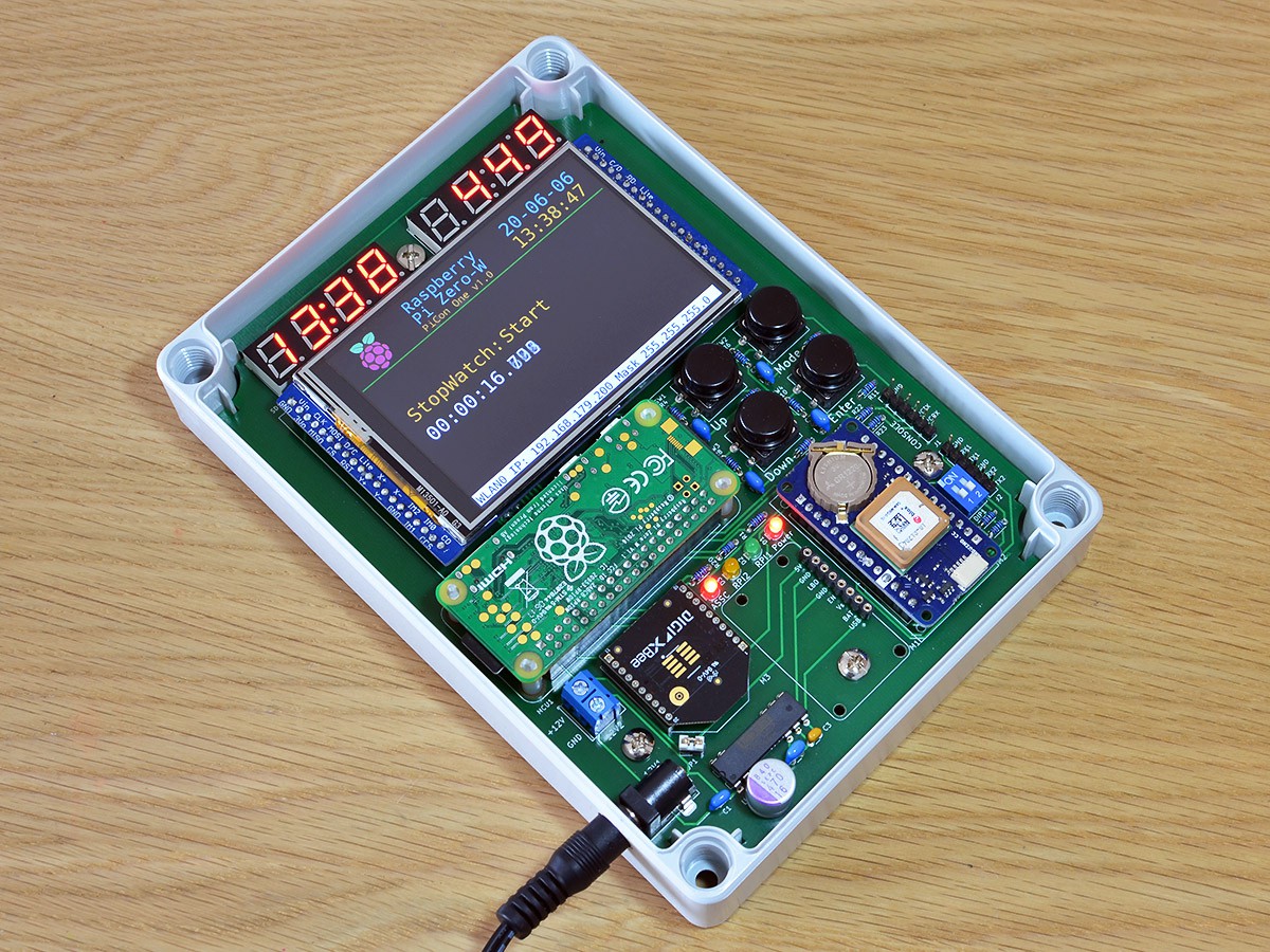
1.) tft-stopwatch
This program is a simple stopwatch, controlled by the Mode, Enter, and Up keys to start, stop, and reset the time. The time runs with 3 digits millisecond resolution. It provides good feedback on the TFT refresh.
![]()
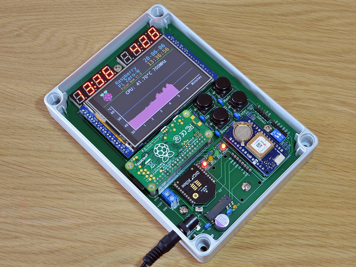
2.) tft-tempgraph
This program graphs the CPU temperature to the TFT. Together with the "stress" program, I use it to simulate CPU load, and check the heat development inside the enclosure when the lid is closed.
![]()
Example load generation with "stress", creating threads for 20 seconds:
pi@rpi0w:~/picon-one-sw/src/tft-hx8357d $ stress -c 2 -t 20 -v
stress: info: [1810] dispatching hogs: 2 cpu, 0 io, 0 vm, 0 hdd
stress: dbug: [1810] using backoff sleep of 6000us
stress: dbug: [1810] setting timeout to 20s
stress: dbug: [1810] --> hogcpu worker 2 [1811] forked
stress: dbug: [1810] using backoff sleep of 3000us
stress: dbug: [1810] setting timeout to 20s
stress: dbug: [1810] --> hogcpu worker 1 [1812] forked
stress: dbug: [1810] <-- worker 1812 signalled normally
stress: dbug: [1810] <-- worker 1811 signalled normally
stress: info: [1810] successful run completed in 20s
-
First RPi Power-Up
05/31/2020 at 04:34 • 0 commentsFor the first RPi power-up in PiCon One, I prepared the Raspberry Pi SD card, using the original Raspbian Lite image. After flashing the card, I updated /boot/config.txt to enable the serial console, adding 'enable_uart=1' at the end of the file. The boards 6-pin console connector links up to GPIO14 (pin-8 TXD) and GPIO-15 (pin-10 RXD) on the RPi, and is made to fit common USB console cables such as FTDI RS232R cable with the 6-pin plug.
The first power-up of a new "alpha" board is a big moment: Will it work at all? And what will it be that I missed this time?
For the good news, the board lights up and the serial console came to life. For not so good news, the board went into a permanent reboot cycle. This happened six seconds into the boot process, exactly when it enables peripherals and I2C. I got a power surge issue.

PiCon One boot-up example (TFT console output set up later) Good power rail design is one of my weak spots, and I have been taking shortcuts for the "alpha" board. I only roughly estimated the power draw, didn't account for peaks, and I am running dual power 5V/3.3V by using 3.3V supplied from the RPi.
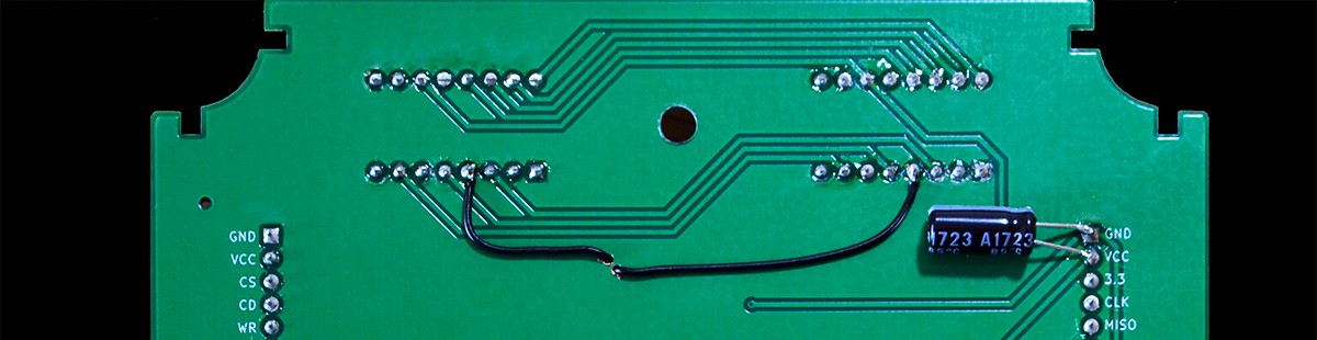
![]()
PiCon One v1.0a backside - bandaid capcitor for the power rail A quick fix was to solder a sufficiently strong stabilizing capacitor. I added 470uF to the 5V power rail on the back of the board. Now the boot process completes fine, and the board is running nice and stable. The 24-test with basic load went OK, I also needed to check out the heat situation inside the enclosure. Doing another proper "burn-in" test is on my "To-Do" list.
If you are reading along and are experienced with power rail design: I'd love to hear recommendations for the next board revision. Improving the power rail is high on my list to get right.
With the board now operating stable, its time to verify and set up the peripherals.
-
Construction Progress
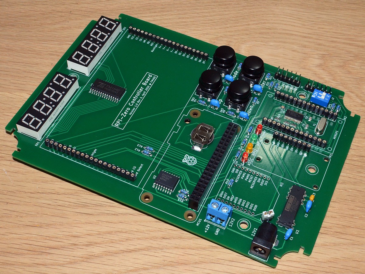
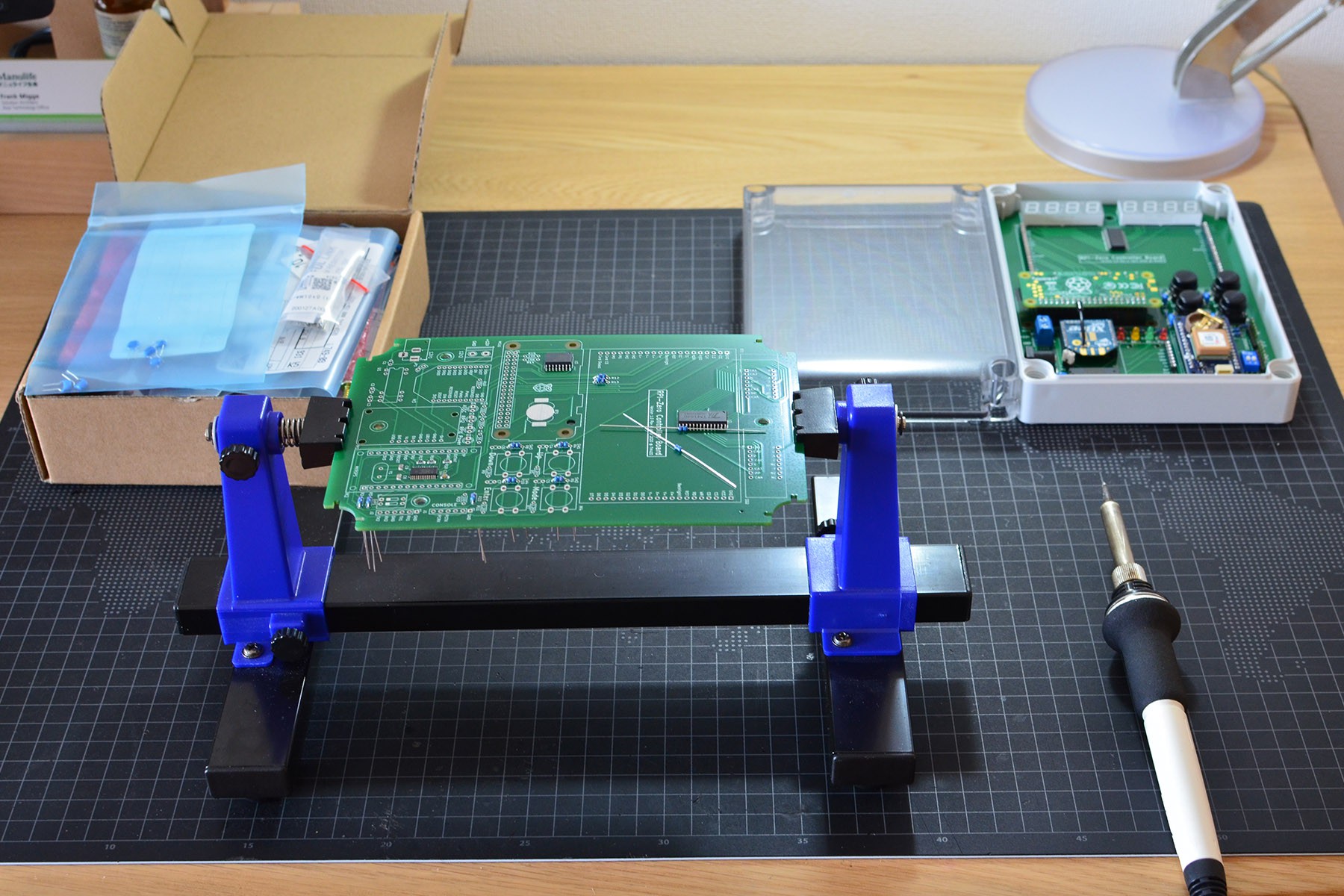
05/30/2020 at 14:08 • 0 commentsSoldering the through-hole (THT) parts into place, this is a view of the "alpha" board nearing completion. The design has quite some space left that calls to be utilized. Adding footprints for common sensors, or even a prototyping area could be placed underneath the TFT display.
![]()
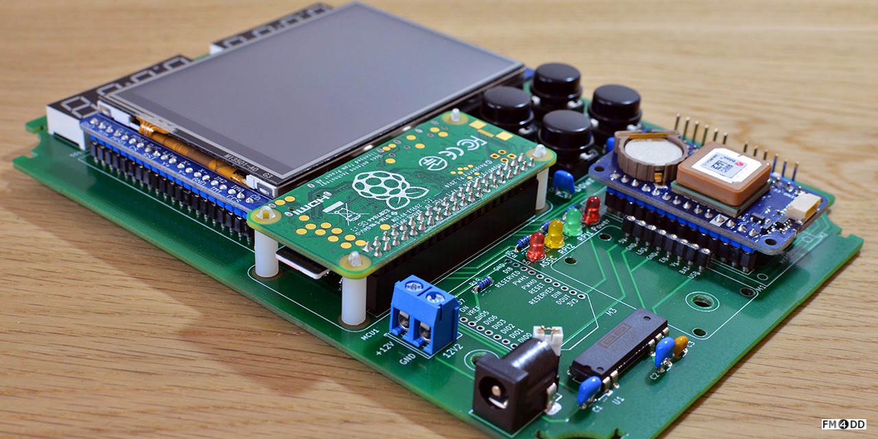
Adding the remaining modules, and placing the Raspberry Pi on stand-offs, its time to power it up. Having four stand-offs for the RPi Zero looks like too much support. Reminder to myself to consider only two stand-offs, opposite from the GPIO, for the next revision.
The RTC IC and backup battery placement should leave enough clearance for a passive cooler installed underneath the RPi CPU, something I still need to validate.
![]()
-
PCB assembly
05/29/2020 at 05:41 • 0 comments
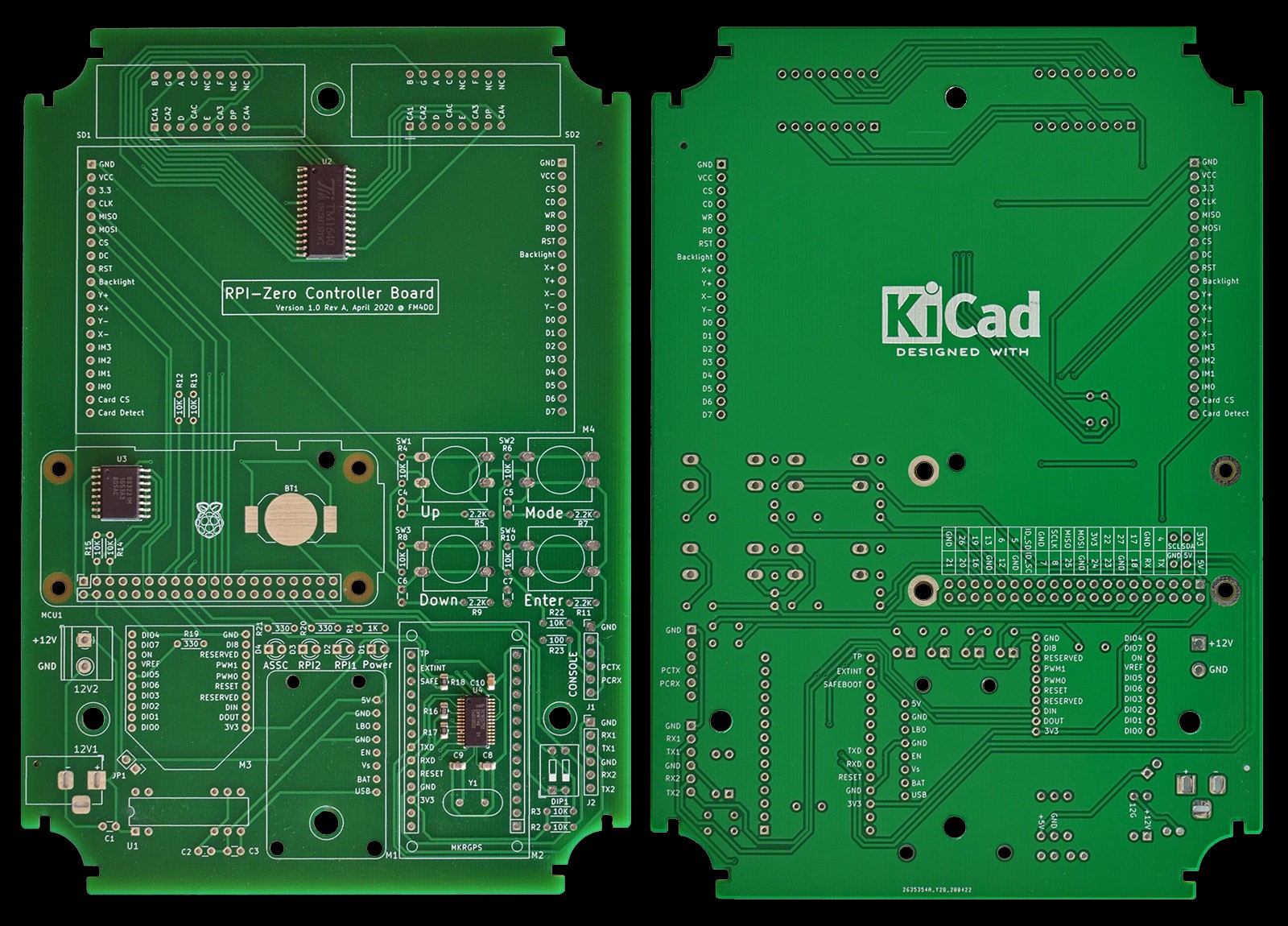
The manufactured PCB arrived with the assembled SMT parts in place. The PCB is made of an FR4-Standard Tg 130-140C, 1.6mm 2-layer board. Its size is 118mm x 168mm.![]()
The remaining THT assembly is straightforward.
![]()
Most critically, the PCB size fits into the enclosure with the exact right amount of tolerance. The first issue to note is that the mounting hole sizes are too small. The enclosure requires M4 screws. Thanks to sufficient clearance, manual drilling with 4mm fixed it.
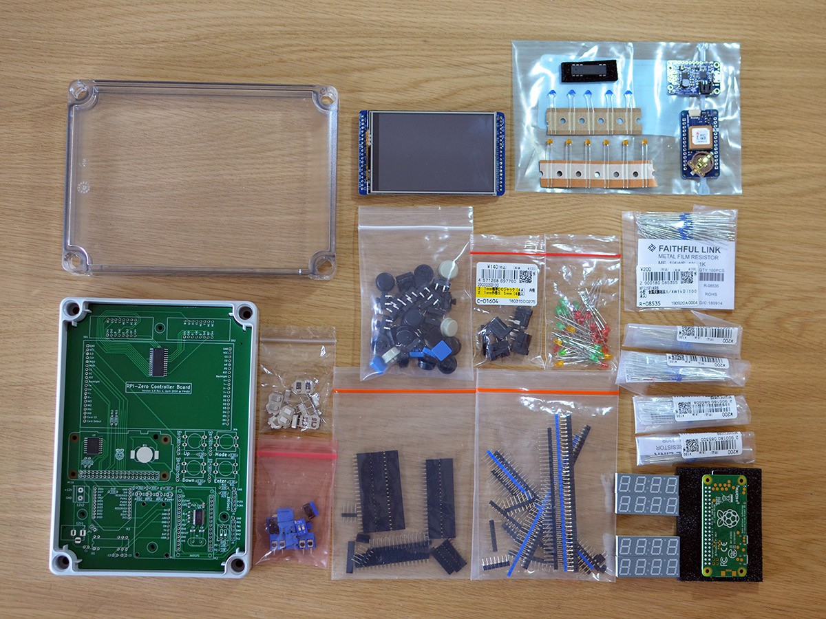
This is what the parts look like before assembly. The full material list is available in Github.
![]()
-
Requirements and Goals
05/28/2020 at 05:57 • 0 commentsRequirements and Goals
During work on the Suntracker 2 R4 project, the code base quickly grew and it became increasingly harder to develop for a bigger set of I/O components and functions without support of an operating system. While capacity requirements can be solved by upgrading to a larger MCU, I wondered if a SoC approach, using a Raspberry Pi or Beaglebone etc, is better suited for a central controller and communications hub device. It should have a compact design with environmental protection, have status displays, and support both external and local communication.
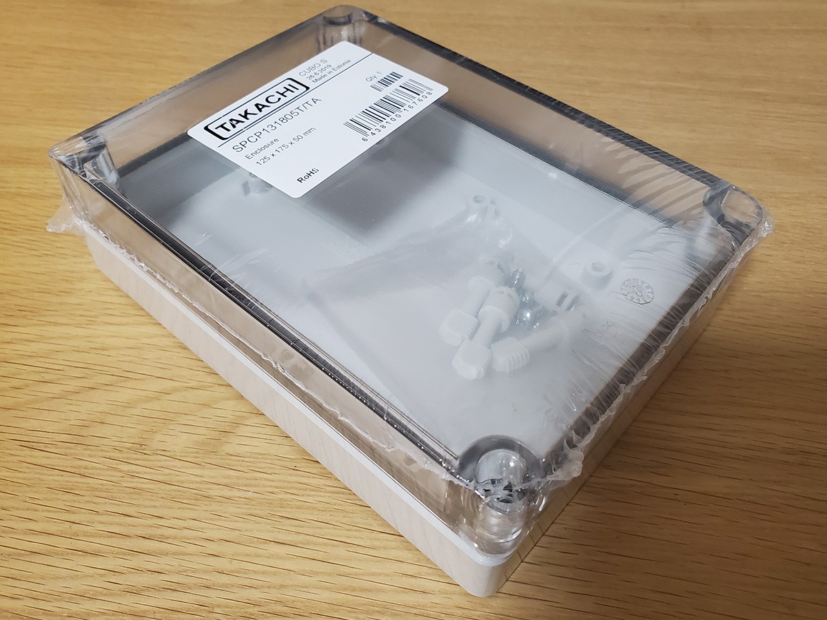
As the target enclosure, I selected the Takachi model SPCP131805T as the best option in size, and the acrylic top.
![]()
Takachi SPCP131805T, 125x175x50mm Schematics
The schematic can be seen in the Github hardware repo (LINK).
For fitting the PCB to the enclosure frame and mounts, a DXF CAD drawing has been made to size the PCB, which I then imported into KiCad.
One of my wishes are to have a detail TFT display. Standard HDMI solutions even at 5" exceed the enclosure width, which let me compromise on a smaller SPI-based 3.5" TFT. For fast changing parameter monitoring, I added two 4-digit Segment displays. I wanted Xbee communication and GPS module support under standard Linux 'gpsd', which required to add serial ports into the design.
Finally, a basic set of touch buttons were added to control settings, which I prefer over touchscreen for simpler GUI programming, and greater reliability.
This is the first time I attempt an SMT PCB manufacturing, and to include factory assembly. I worry for mistakes, so I keep the SMT component count small for now. Most components stay THT for self-assembly, avoiding bigger loss in case of mistakes.
PiCon One
PiCon One is a multi-function controller for home automation and industrial use cases.