Hardware, LED sensor circuit, Version 1
Entunassas Contribution 6 (09 Jun 2020):
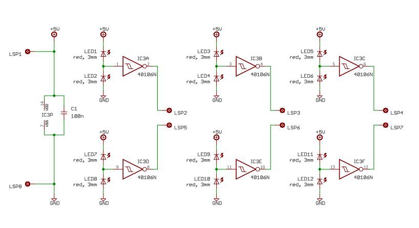 This is Version 1 of the sensor schematic.
"LSP" are connection points to solder a cable to (german expression is Lötstützpunkt, hahaha)
LSP1 = +5V from ARDUINO
LSP2, 3, 4, 5, 6, 7 = Outputs, shall be connected to digital inputs of ARDUINO
LSP 8 = Ground (0V) from Arduino.
One have to consider the ambient light falling onto the Sensor LEDs should be nearly equal. Also the ambient light shall be low compared to the STATUS LEDs light. Therefore you have to dim the ambient light influence.
A calibration is needed for each sensor. To get familiar with the behaviour of this circuit, do some tests with your individual assembly.
Try influence of
- ambient light
- STATUS LED brightness
- dim/shadow the not used SENSOR LED
(Find the final schematic V1 in section "Files" as PDF also.)
-/-

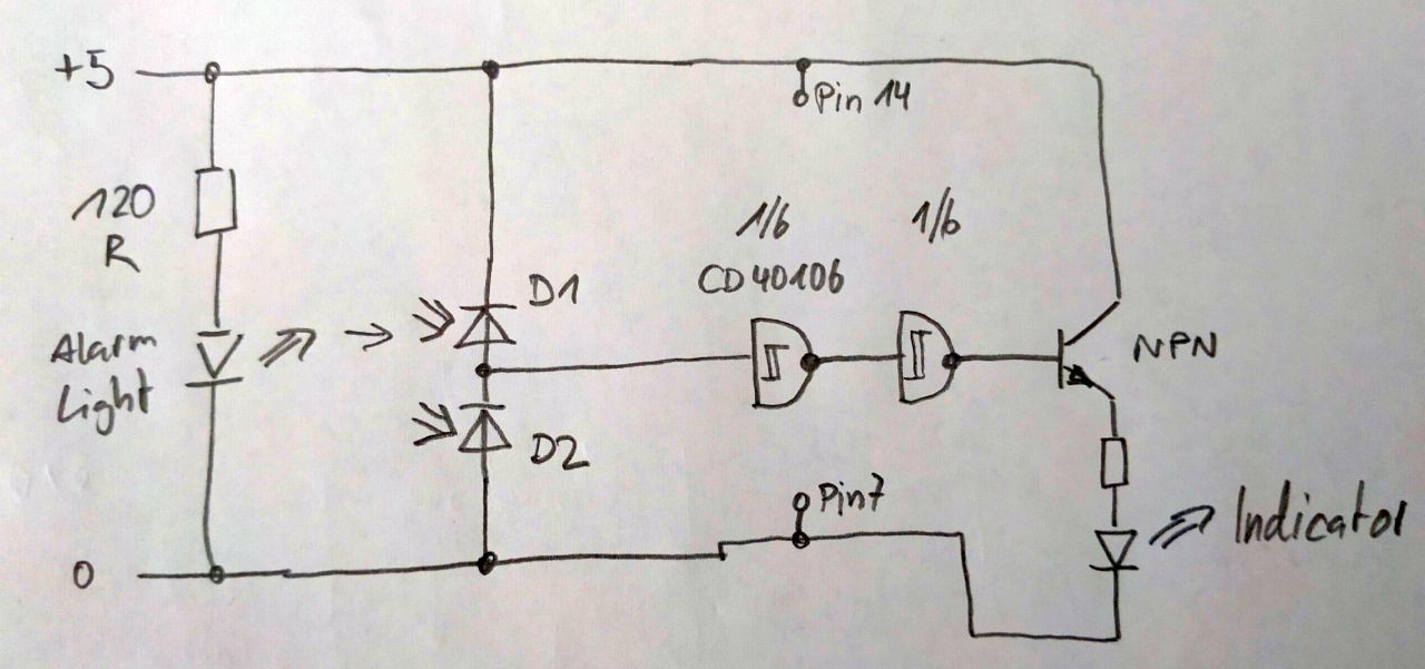
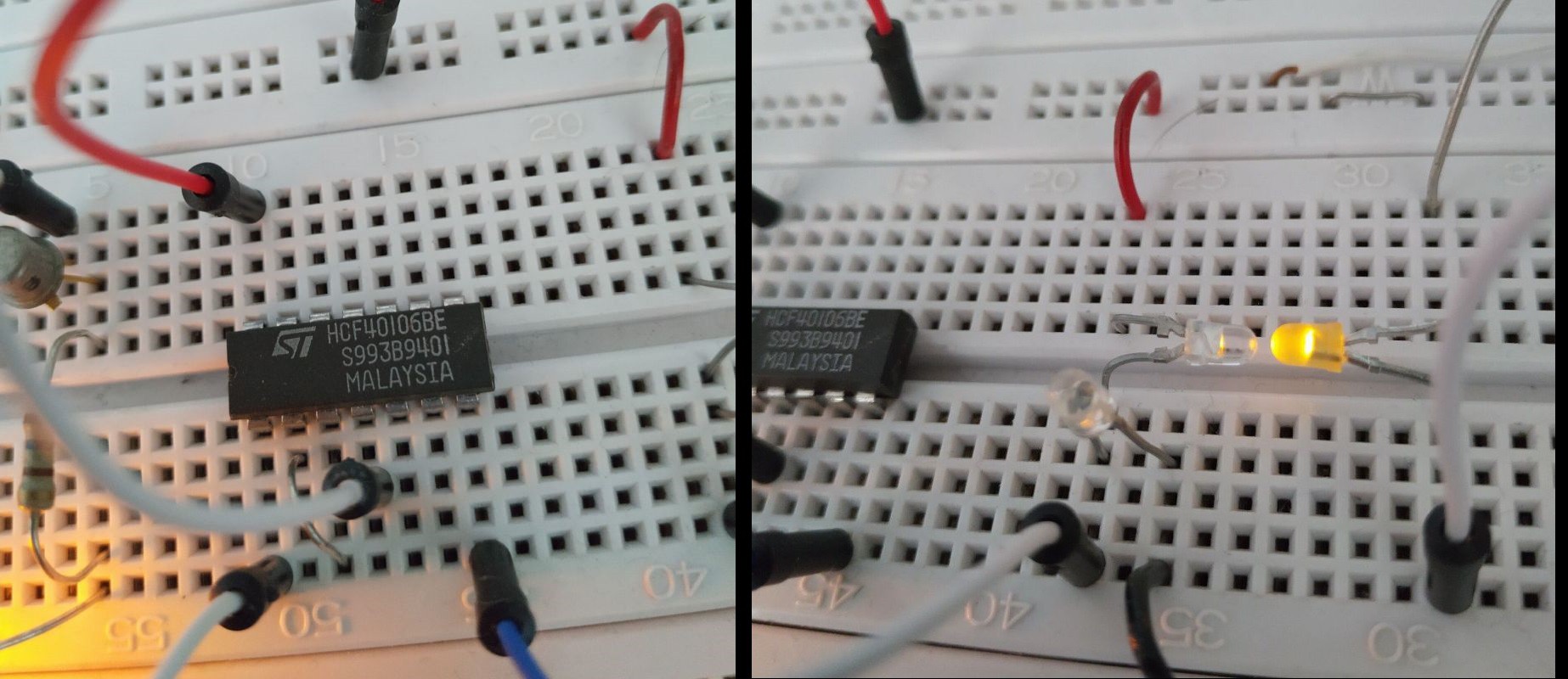


Hi Eric,
I think it's a great idea. It occurred to me spontaneously that if you wanted to forward an alarm message from more than just one location, you could use a small cheap ESP32 board with an Arduino MQTT client at each location instead of the Arduino with Wifi shield and send the message to a central Raspberry running an MQTT broker. Of course, the Raspberry would also need an MQTT client so that it can evaluate the alarms that arise and forward them as an email or message to a smartphone or PC. The Eclipse Paho MQTT Python client library would be a good choice for the Raspberry, because Python can easily be used to control the processing of the alarms.
Greetings Micha