When I did my first SMD project I needed a way to test the circuit on a breadboard. The device I had, the TM1637, is in a SOIC-20 package. I ordered a few of these typical breakout boards from eBay.
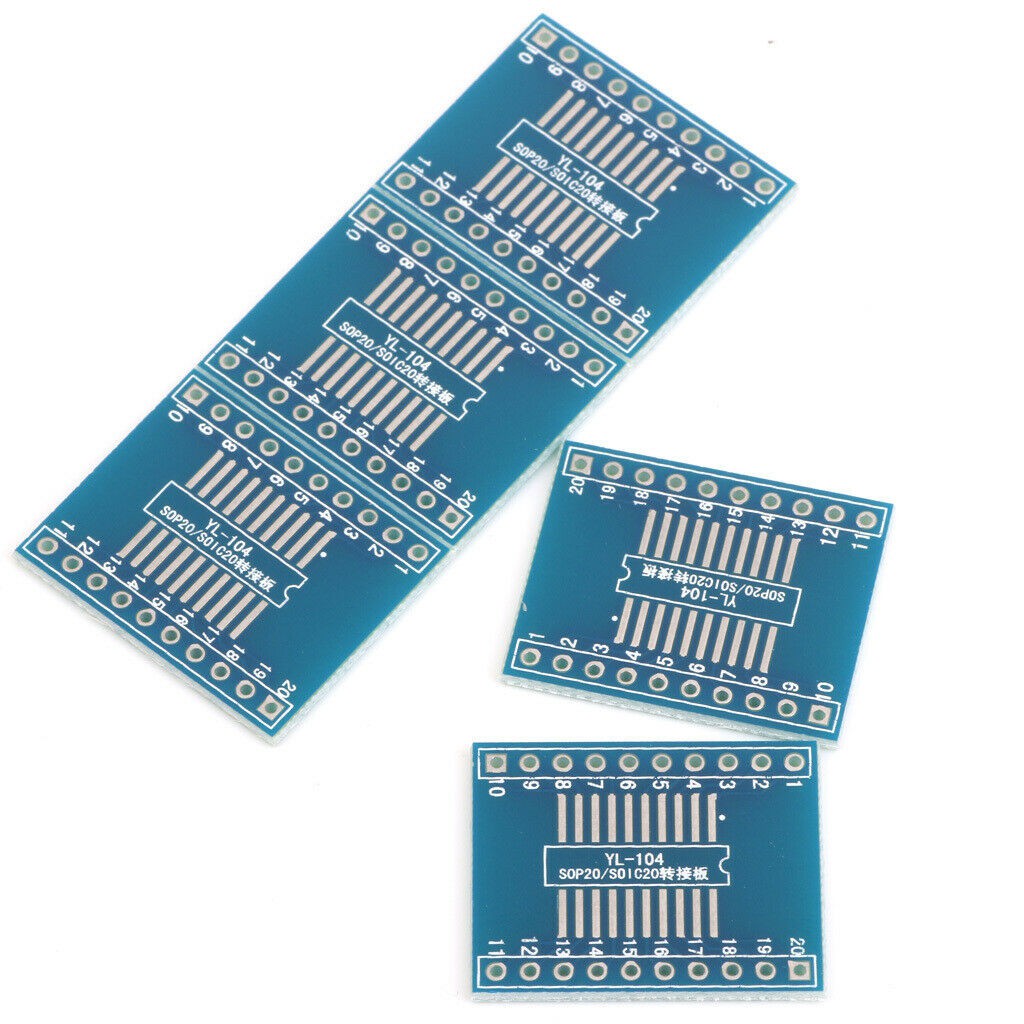
The reverse side caters for TSSOP-20 packages. However these boards cost about $1 each after shipping, even more due to reduction of cargo traffic in these COVID-19 days.
What if I could make a panel of such boards and have them fabricated? It would cost more initially, but you would get a large quantity in one order. Not just for 20 pin packages but for other packages, such as SOIC-8. Naturally the smaller the package, the more you can fit on the panel.
I found a Github repository of breakout boards by Kevin Neubaur. They are in Eagle format but it's trivial to import them into Kicad. For the panelising I found a GIthub repository of a Python paneliser by Simon John. I'm grateful to them for publishing their work which I build on.
Update 2020-06-29: I have come across KiKit which seems to be a more advanced panelizer. I haven't tested it. It may require Python 3, in which case I have to wait for the Python embedded in my Kicad to catch up. End update.
JLCPCB indicated that they would be happy to sponsor my samples, so I thank them also. I chose to use V-cut panelisation as this doesn't waste as much PCB space and also leaves smooth edges compared to breaktabs and mousebites. I will report back when I receive the samples but I don't expect any problems, JLCPCB has always made good boards for me.
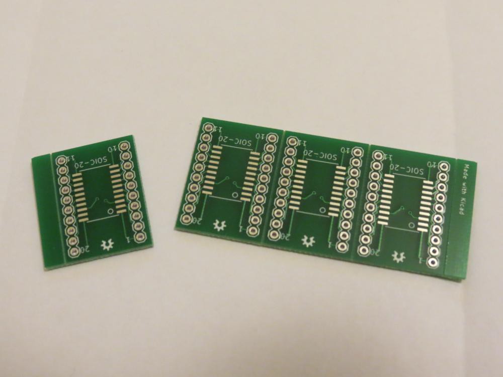
Update 2020-06-23: Boards have arrived. 23 days since entering the order so about 3 weeks shipping. About as good as can be expected for economy shipping these days. It was very easy to separate the boards by flexing back and forth a few times. Here's a photo, sorry about the orientation.
End update.
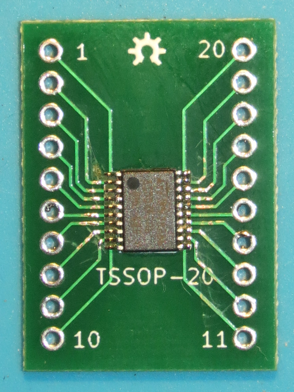
Update 2020-07-11: After a lot of procrastination I have successfully soldered a TSSOP-20 chip to a breakout board. TSSOP-20 is half the pitch of my last attempt, so correspondingly harder. What I realised is that in future I need a magnified platform, and a shorter soldering iron. Applying the flux and later the solder paste with a toothpick was not hard. The positioning took the most effort. You can see that I'm still a couple of degrees off. Swiping with the chisel tip was fairly easy. Then clean up with some isopropyl alcohol. I checked for continuity and shorts afterwards and I seem to have succeeded.
End update.
One problem I had to overcome is that the paneliser script required the Kicad pcbnew Python 3 module. My version of Kicad only supports Python 2, which has reached End Of Life. (Kicad is transitioning but there is work to be done.) I found that the way around this is to use the pasteurizer tool which converted the script to something Python 2.7 would run.
I have converted and panelised a few boards into my repository, see the links of this project. You can fetch the Gerber files, zip them and you're ready to order. If you would like another board converted or panelised, please leave a comment and indicate which one from the original repo and I will add it to my repo.
You can also do panelisation yourself using the tools I did. One tip, when viewing the panel in pcbnew, turn off visibility of the Dwgs.User and F.Fab layers or you will see lots of extra text. Also the 3D viewer will complain it cannot find a closed outline due to the V-cuts going across the board but will still display the board.
 Ken Yap

 facelessloser
 zacnotes
 Flavio

 Torbjörn Lindholm
Oh nice :D one feature request... I've noticed two distinct kinds of QFP packages over my few years of tinkering. I call them (generally) "old" and "new" QFPs, because the use generally breaks down along those lines. The "old" QFPs are rectangular in shape, such as with eg the Sanyo LC7942, an LCD driver/controller which, along with its companion chips, the LC7940 and LC7941 (which are identical except for a mirrored pinout), are common on older LCD modules as commonly found in early laptops as well as portable word processors. The "new" style QFPs are square, seen as used by the NEC V53A "SoC" (p/n UPD70236AGC) or, anachronistically, the Sanyo LC7980 LCD controller chip, occasionally, but less often, used in a similar capacity to the previously-mentioned LC7942, although with different chips.
While so-called 'DIP adapters' are easily available for square/"new" QFPs, I've never seen one with the proper footprinting for rectangular/"old" QFPs, and that kind of annoys me, because then I can't use those.
Maybe you could whip something up for that...?