-
Generation 2 PCB is born...
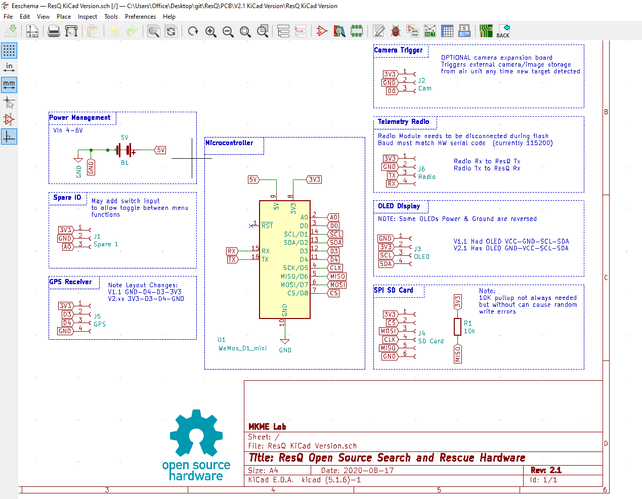
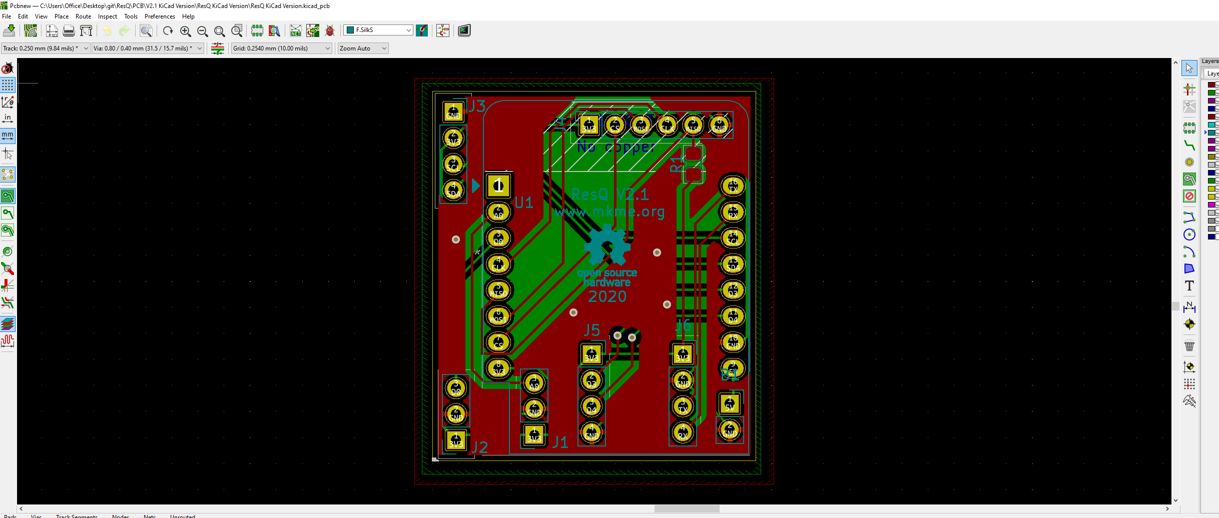
09/07/2020 at 00:04 • 0 commentsSince it is a long weekend I decided to make some time to learn again and KiCad was on the menu. I already had the basic schematic made for version 2.xx of the ResQ PCB so I made a few changes this morning and ended up with something I am fairly confident in
I watched a few YouTube tutorials then just started pushing traces around the board :) I found routing to be very intuitive and had little problems until it came to the silkscreen stage but all was smoothed out in no time.
I know I could do a bit better on the copper fills but I didn't want to waste the whole day in front of my PC so once I got to this stage I uploaded them to PCBWay for production.
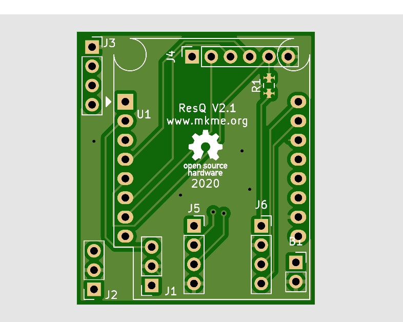
Top:
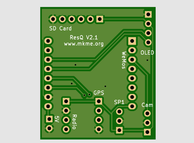
Bottom:
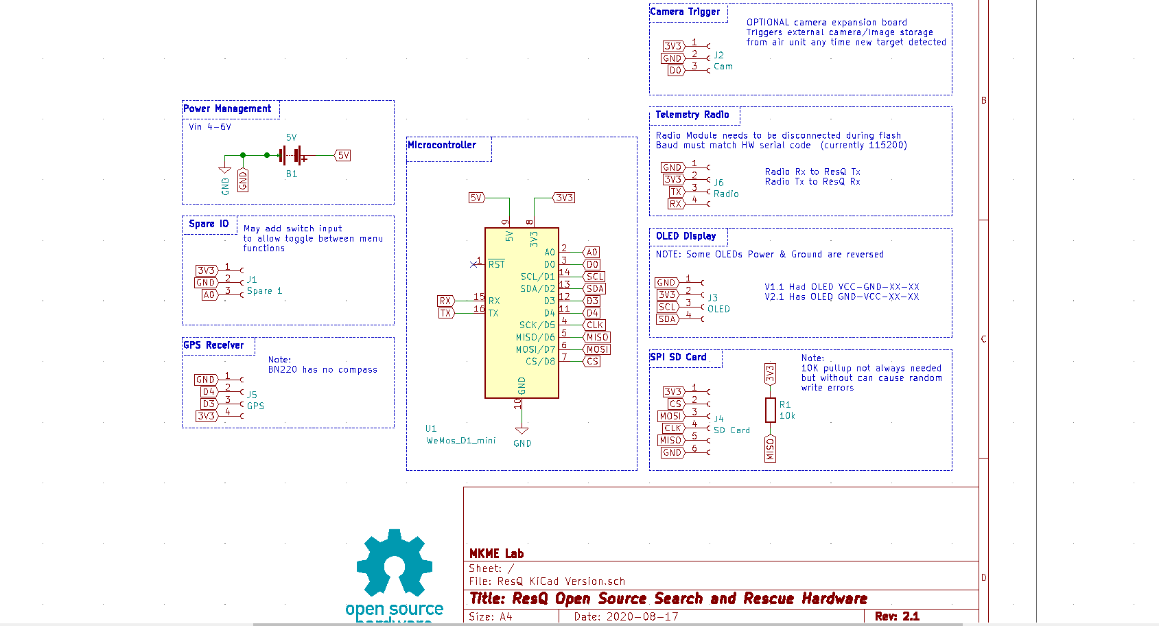
The primary changes are called out in the schematic and readme files but now I have the extra expansion I/O (all 3) broken out and the OLED connection changed to match the more common units available.
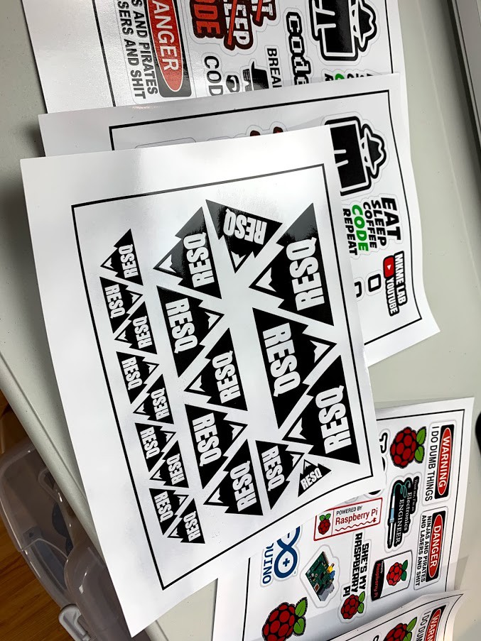
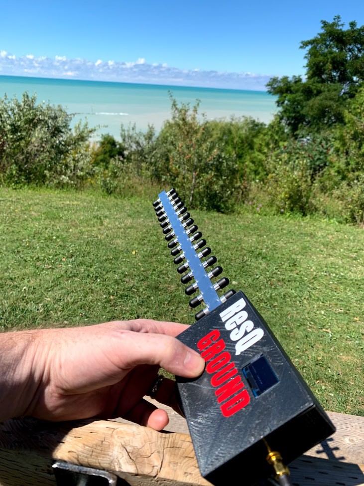
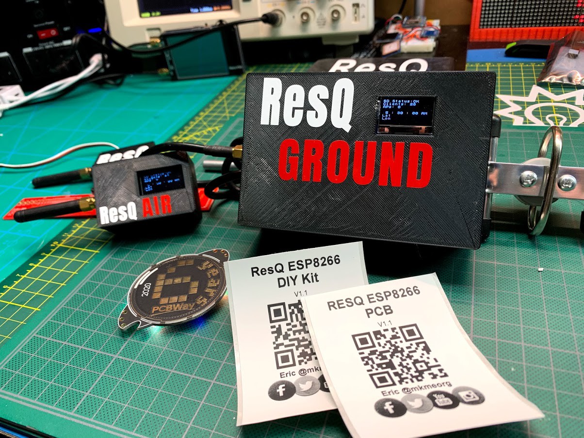
I also made a bit of time to whip up a new logo/stickers just for fun. I printed them out for cutting on the Cricut Maker.
![]()
I posted the photoshop source file and print files in a new folder in the Git Repo in case others want to print their own too. I'll try to make some kits this week and of course will include some stickers with them.
Every day I get to post updates with new things I've learned it really gives me a sense of accomplishment. What a fun project.
I ween.
-
Build Video Part 2 is Up
09/05/2020 at 23:36 • 0 commentsYesterday part 2 of the build series finally went live. There is a several week lag due to shooting, editing and publishing. All while I am also doing the builds and documenting it all here too :)
I have already been working on Part 3 which includes the ground unit assembly, another prototype and the final testing already posted in build logs here. The videos should help show a lot more of the details and information.
Enjoy!
-
Success!!! It works well indeed
09/03/2020 at 20:19 • 0 commentsAfter the rain passed on Sunday I was able to get out and run another proper field test with the ground unit. Video of this test and all the case builds should be live in a few weeks (part 2 only airs tomorrow on YouTube) so here is the text version...
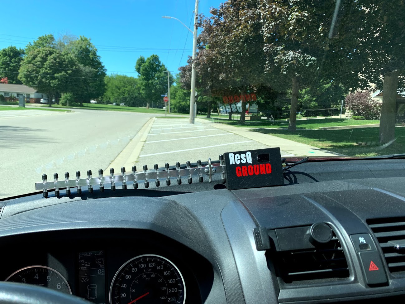
I set the unit on my dashboard and went for a drive- sure enough lots of hits
![]()
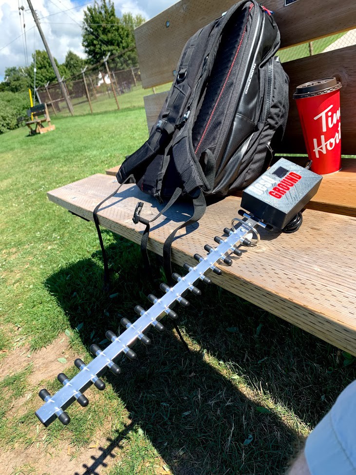
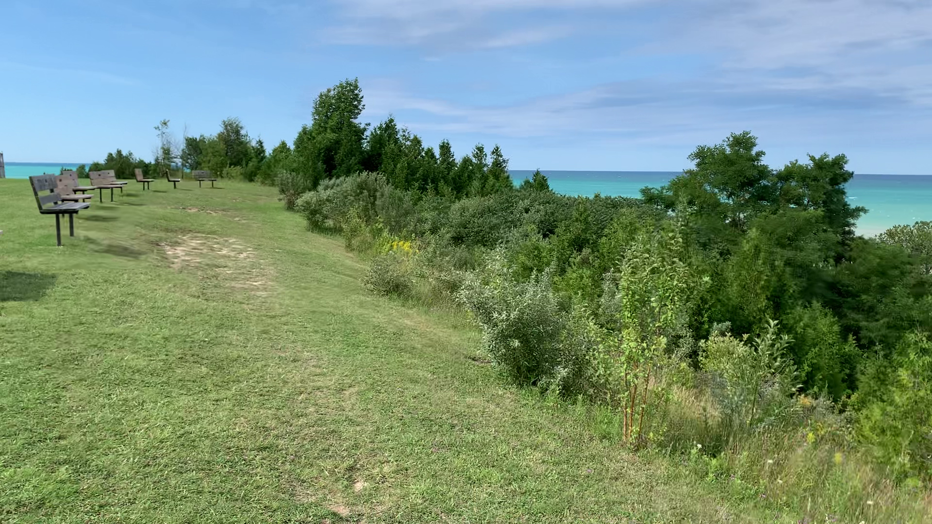
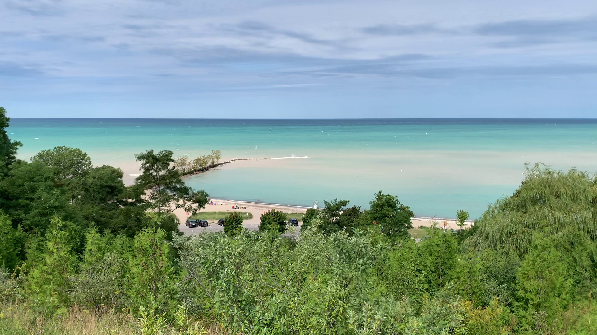
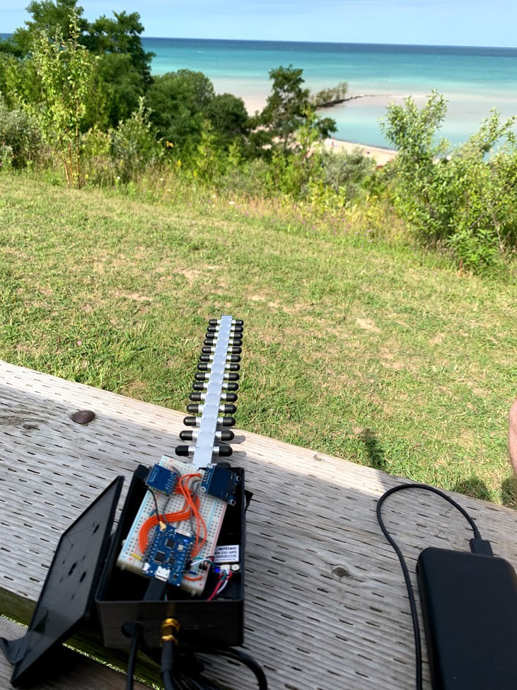
I headed over to my spot above the cove beach. Same as last time- I'm about ~200 m (I think) above the beach and there are also plenty of trees between me and my test subjects. There were a few people around me but the majority are far down below:
![]()
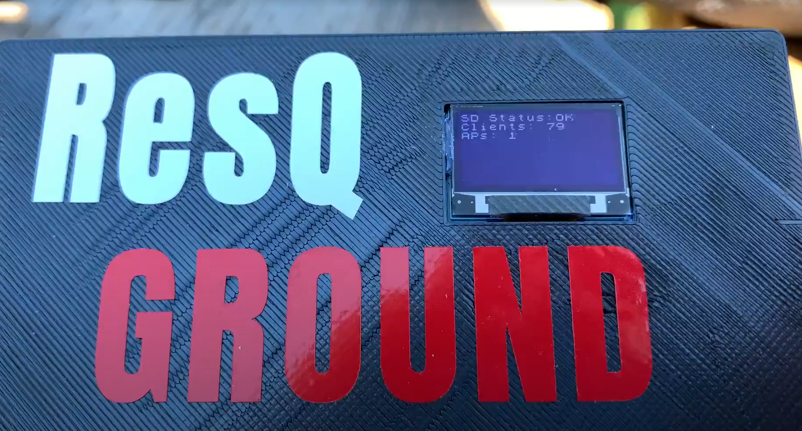
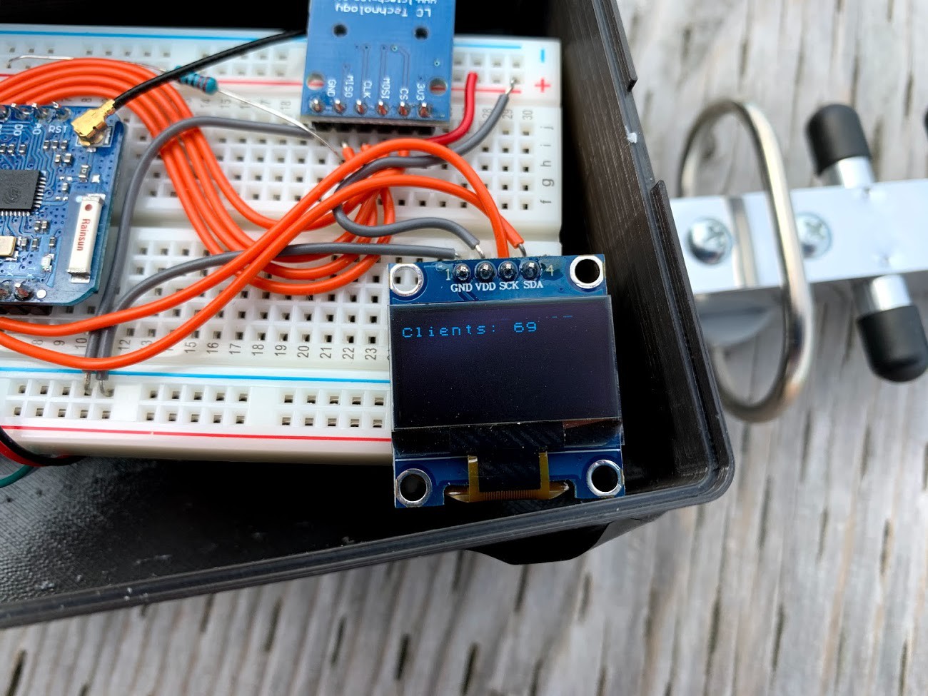
Again the YAGI didn't disappoint and the MAC count rose above 100 in no time
Since the rolling shutter effect only lets let me photograph half the display- here is a video https://photos.app.goo.gl/TTCBib6QPf9TkPNYA
It's a bit crazy how well this works since I'm not even at the edge of the cliff/bluff so the ground and trees are definitely attenuating most of the signals from below. Neat
![]()
It works so GOOD! I couldn't be happier.
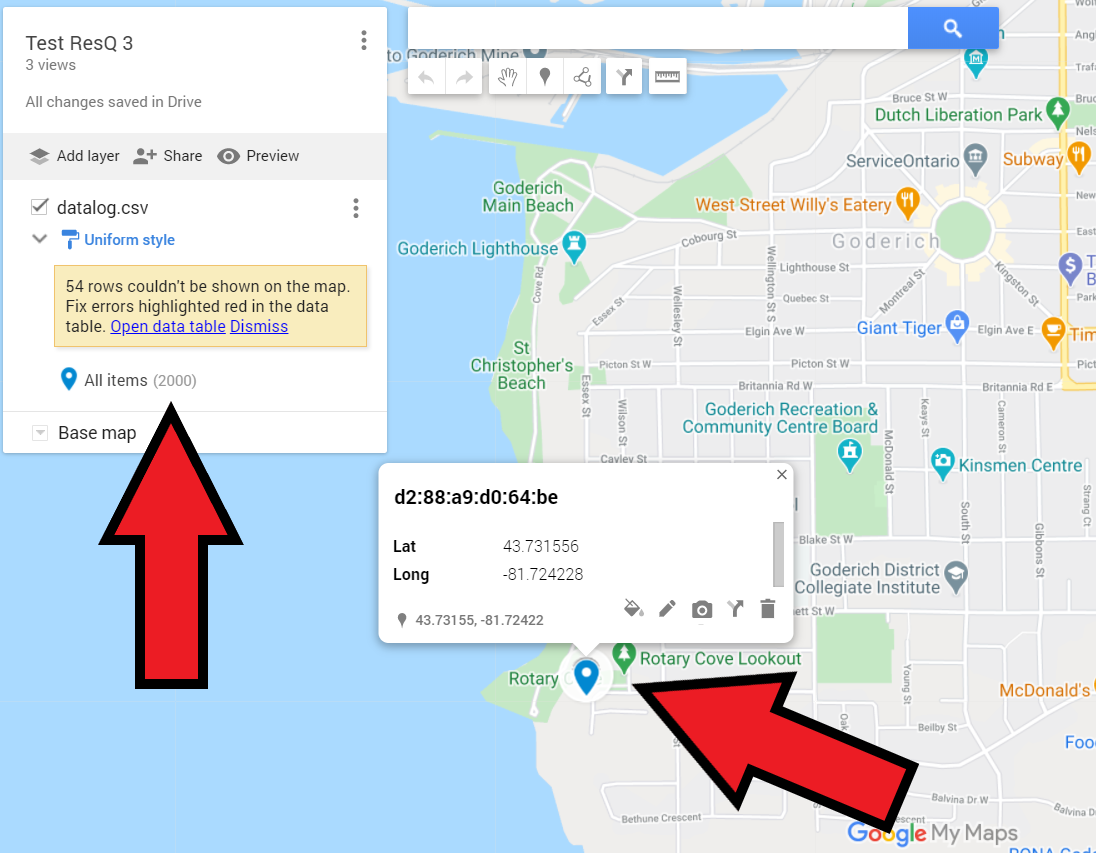
When I got home I started to write the instructions for how to plot the GPS locations on a map. It is no problem to upload the .csv file to Google Maps and plot up to 2000 hits at a time. It is limited to 2000 so you just have to copy/paste if your file has more than that (hopefully not if you are doing a search )
I added the instructions to the readme on GIT and have updated the user manual which I will release in some weeks (it is over 40 pages now but needs more to make this project even easier for anyone)
![]()
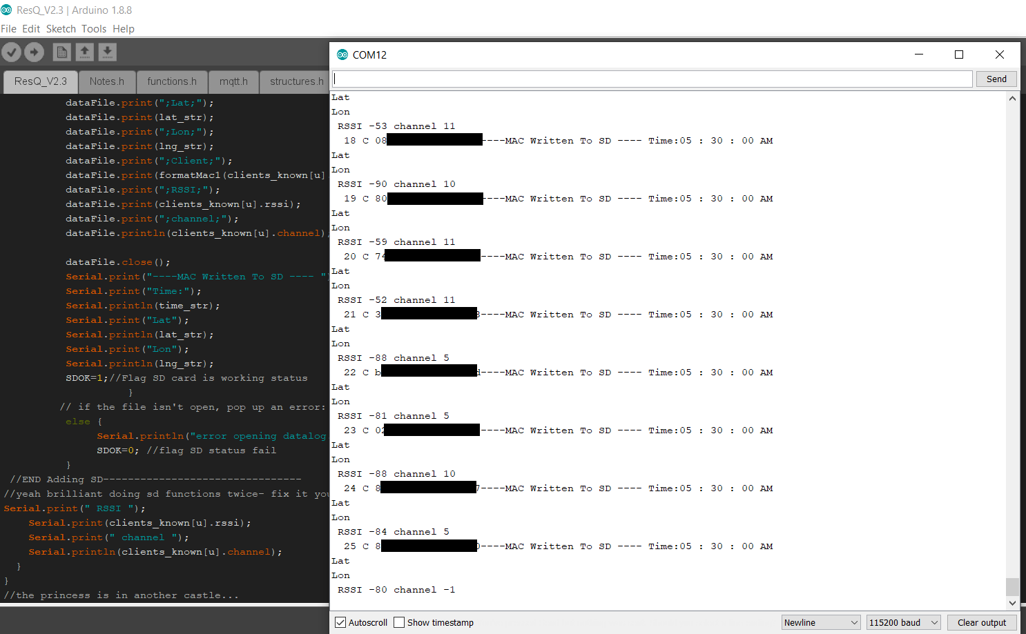
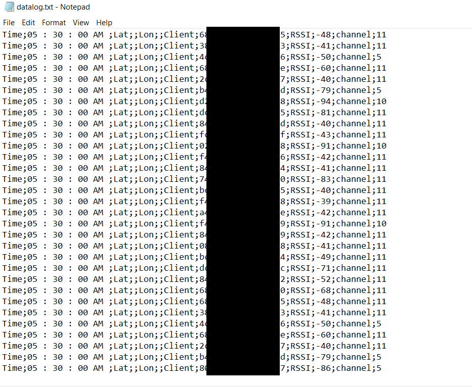
Last night I pushed a new code release to GIT which removed the logging of AP's to the SD card. This just added noise to the dataset that had to be removed before Google Maps can easily take the file. They are still logged to the display and serial though because- why not.
Here is the serial communication currently (note this is in my basement so no GPS location fix but it gets time no problem)
And here is the data file from the SD card. Nice and simple .csv which Google maps accepts directly (good idea to add column headers as I instruct in the readme)
So at this point I see no need to add any amplification to the RF circuit. Because we are not dealing with any data transfer- just getting the ID, it seems as though the system is pretty robust and can pull MAC addresses and RSSI right out of the noise floor :) So it seems anyhow.
We will know more once some others play around and test this out for themselves. So far- I think I can move on to finalizing V2.xxx of the PCB and make some kits available to people who might want one. Will see how it goes.
I ween.
-
Case conundrum...
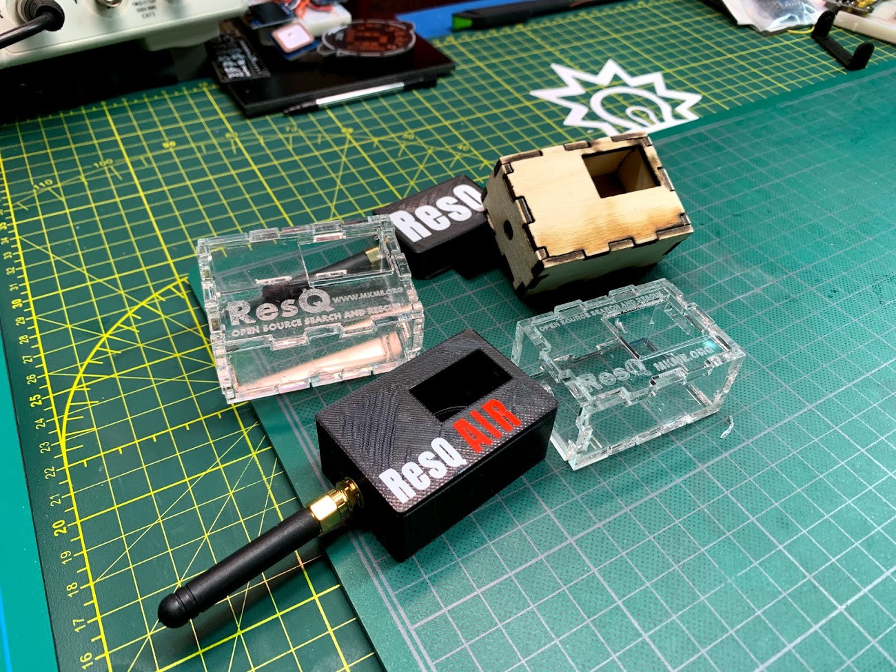
08/30/2020 at 19:45 • 0 commentsThe weather started out horrible this weekend (kept my test subjects away from the beach) so I decided to tackle the case problem. I really like the state of my 3D printed cases:
![]()
But there are 2 fairly serious issues:
- Not everyone has access to a 3D printer
- 3D printed cases would cost a lot for me to ship in kits
Since I really would like to do some kits to possibly bootstrap some funds for the project I really need to solve these. I decided to make a 2D design that can be laser-cut, CNC machined or even cut by hand.
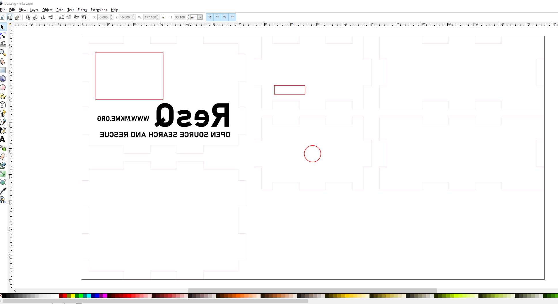
I made this design and modified it in Inkscape to cut on my laser cutter:
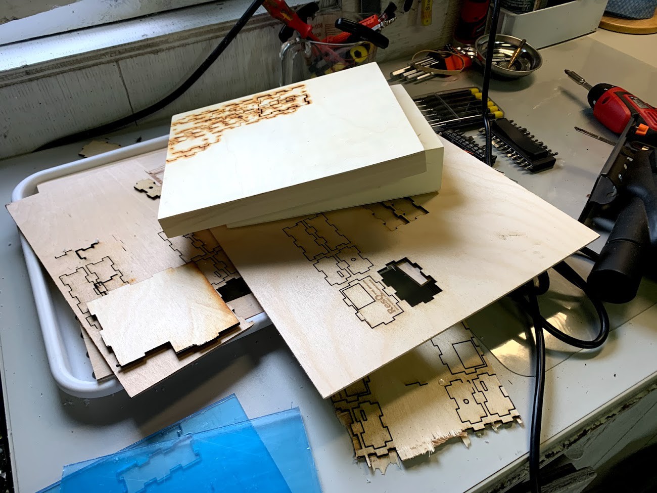
It came out pretty great but I had some issues. As usual, I spent the entire weekend iterating the design with dimensional and format tweaks. Cutting them and trying the assembly over and over again.
![]()
Getting there:
![]()
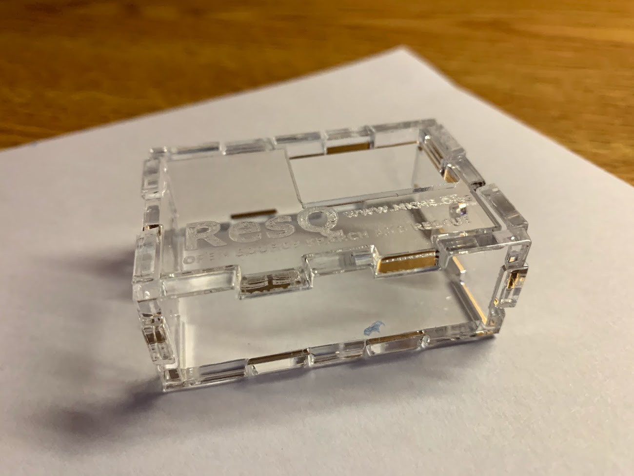
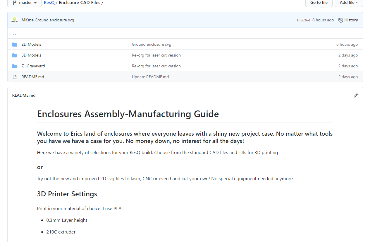
In the end- I now have SVG and DXF files in my GitHub Repo covering an easy to make case for the air unit. I have also added a readme with assembly instructions just for the cases/enclosures and the various methods of making them HERE
Pretty happy with how it came out!
![]()
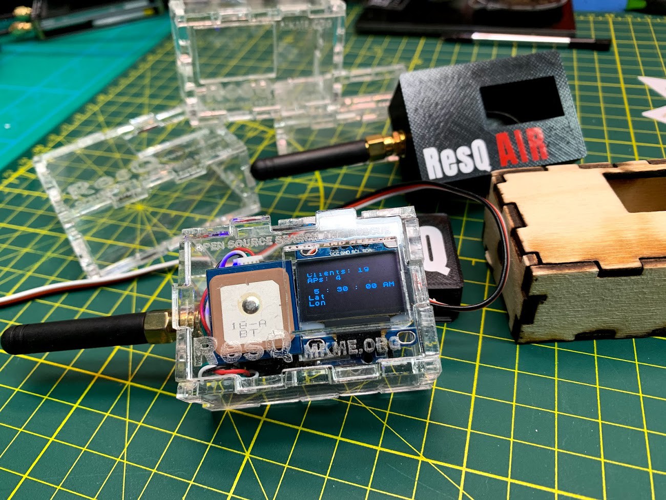
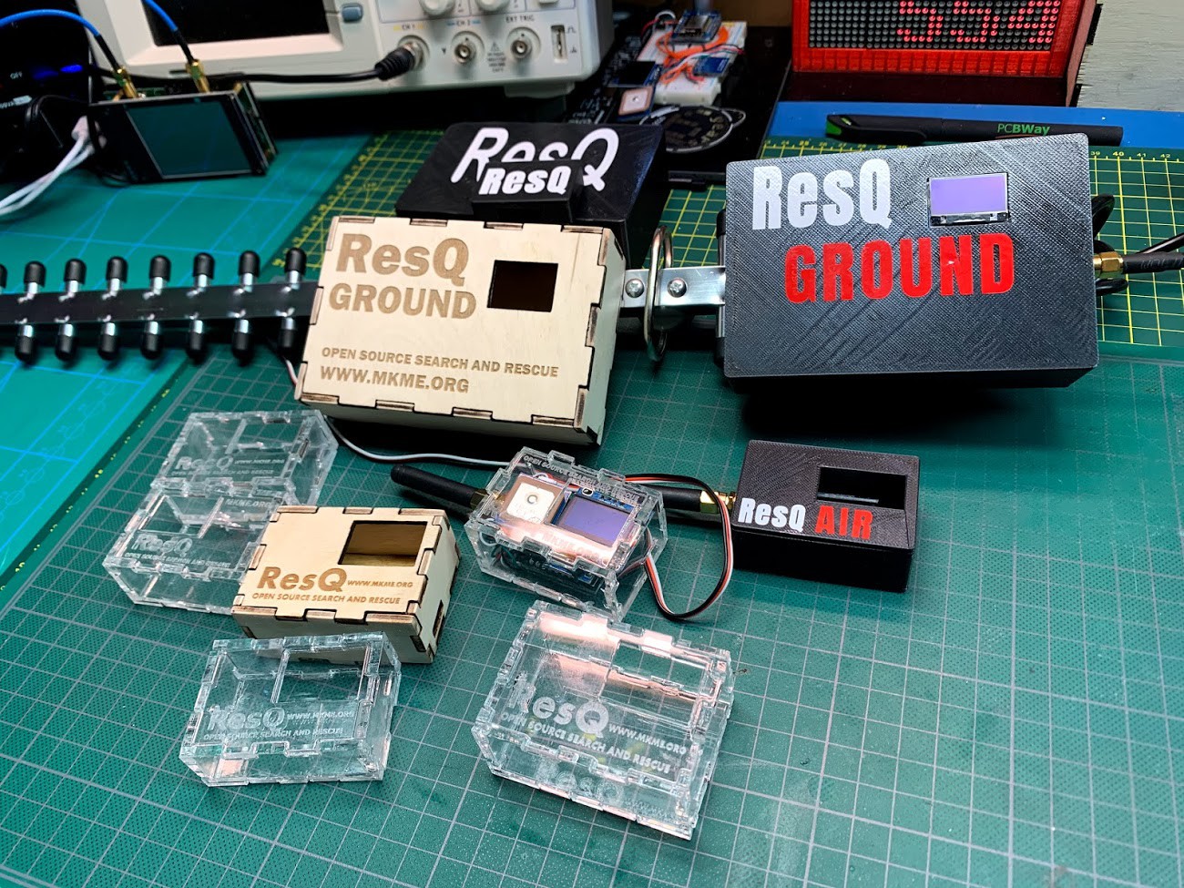
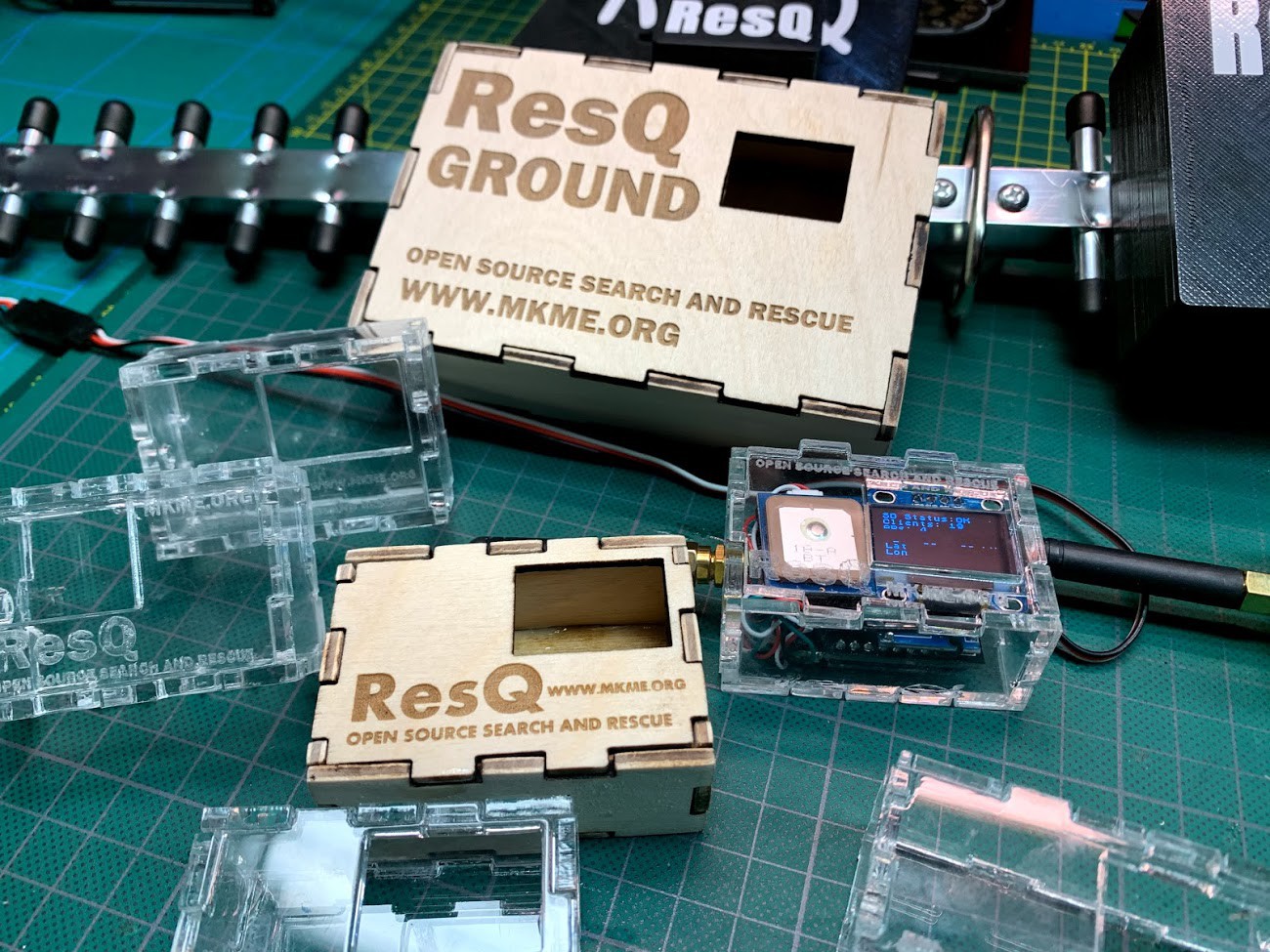
Being flat 3mm thick material- I can now ship a case with component kits when/if the time comes I actually find some people who actually want to buy a kit 🙂 Both 3mm birch plywood and 3mm acrylic seem to work nicely but the acrylic looks waaaay nicer.
![]()
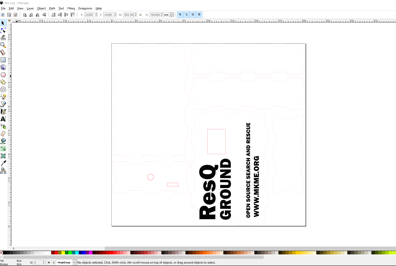
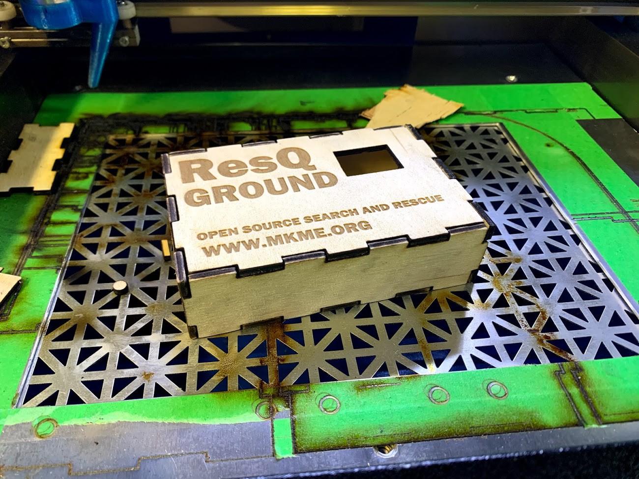
I even went ahead and tackled the ground unit enclosure too. The SVG file was pretty easy since my hardware is the same between air and ground:
It cut out great on the K40:
![]()
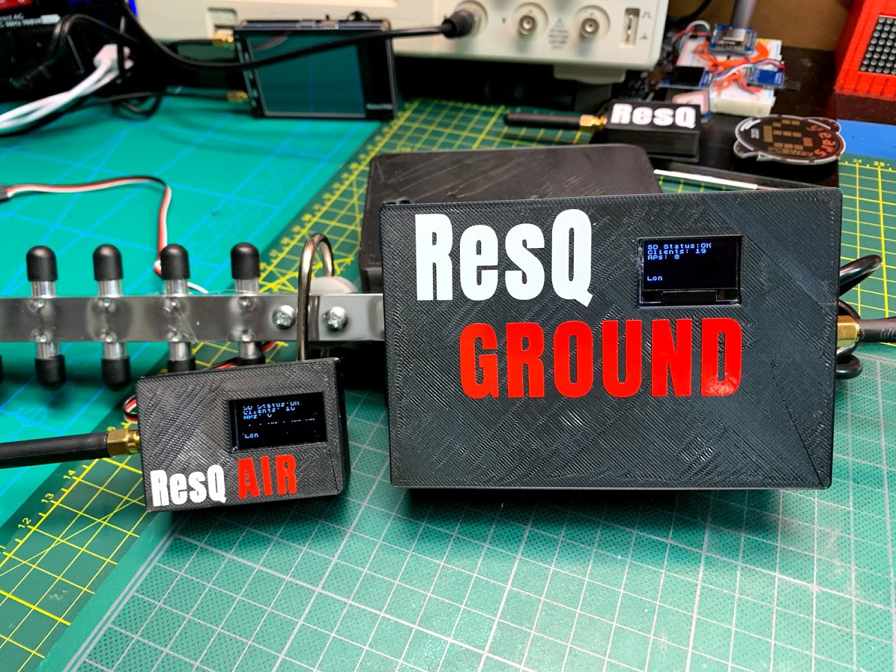
Then one big happy family was together at last :)
![]()
Key takeaway: However long you think it will take to make a simple enclosure- double it... then double it again ;)
Pretty happy with these as the open the door to anyone to make this now without a 3D printer (or with one too)
![]()
I ween!
-
Developing Gen 2 while still testing Gen 1...
08/28/2020 at 00:23 • 0 commentsTrying to update these logs as often as I can so I catch the entire dev process for any future nerds like me who wish to know what crazy road led me to wherever this goes...
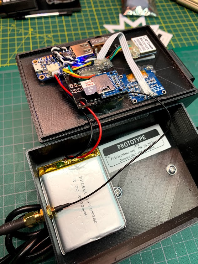
Current state of the ground unit "guts":
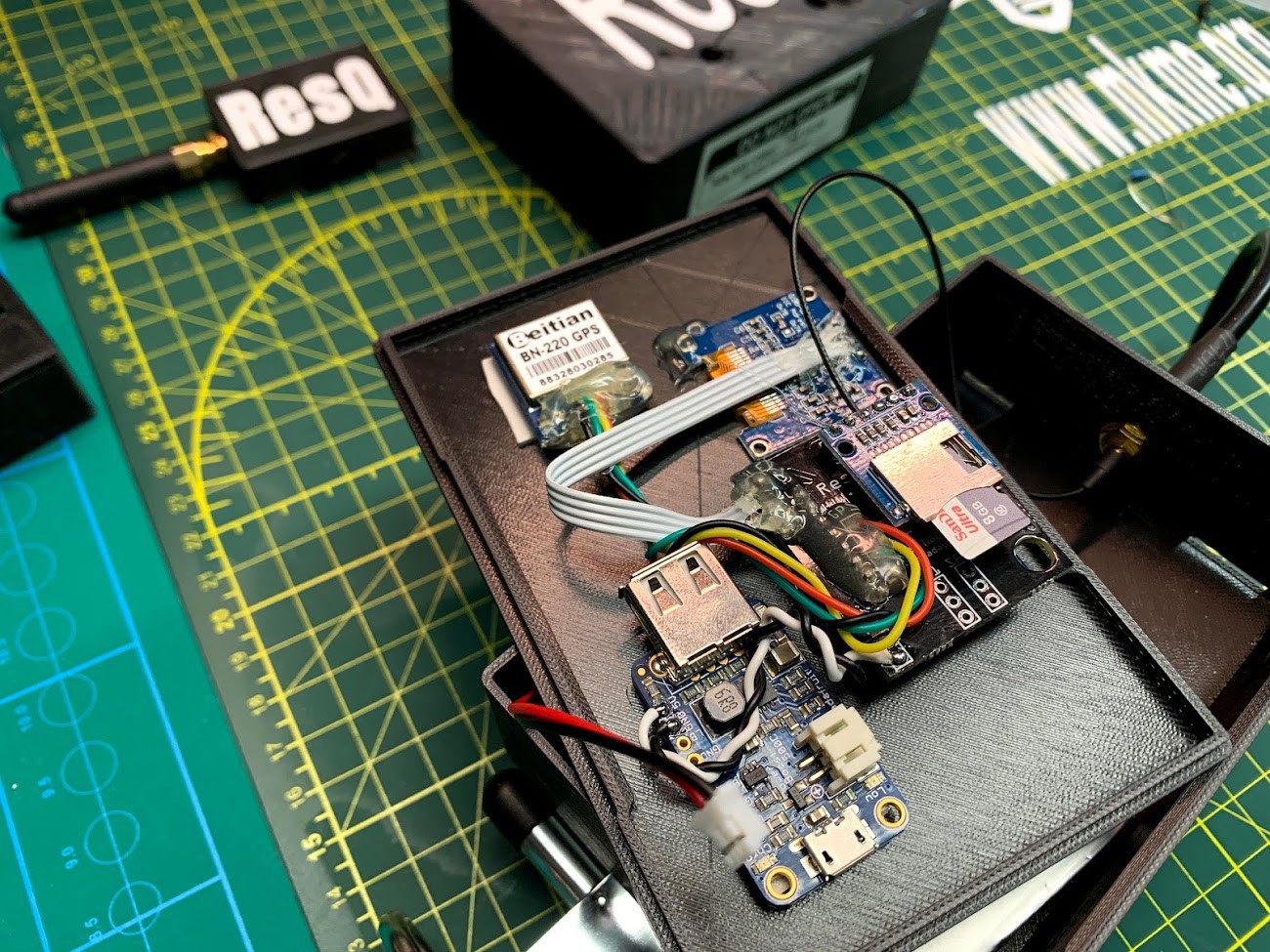
![]()
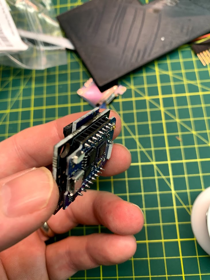
I Added an Adafruit PowerBoost 500 for battery supply and charging. Note the Prototype sticker- I'm learning to label EVERYTHING. It even has the PCB version number. This makes my life super easy when reviewing my testing notes and videos. I wish I bought a label printer YEARS ago now...
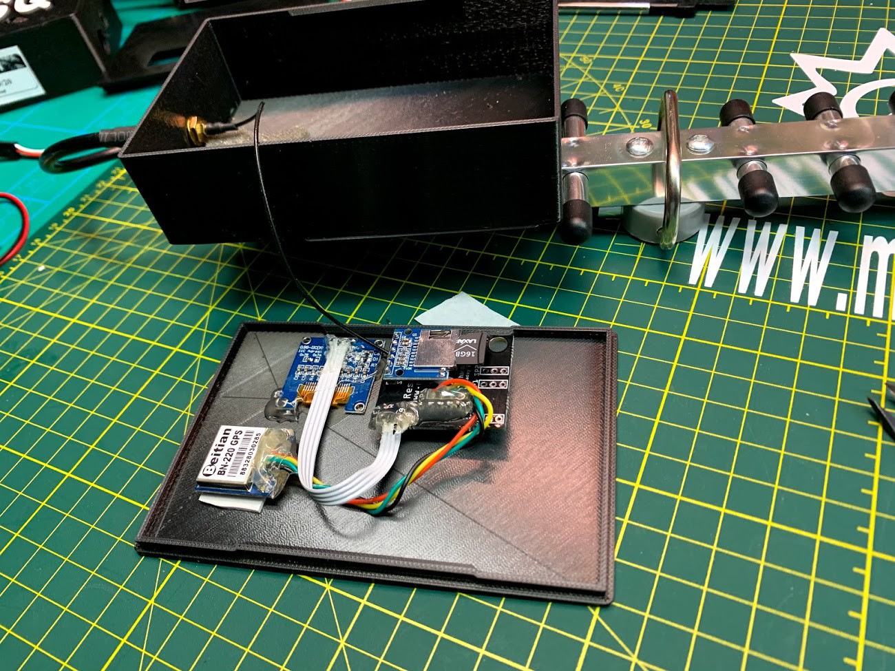
Walking in to my workshop tonight I found my prototype air unit sitting happily (forgotten) on the bench powered up since last night with full GPS lock, working SD card and 30+ client MACs being tracked. I would say we have a winner. Here is what the ground and air units look like now:
![]()
I like the look of things. This weekend I will take the ground unit out for a bunch more tests but in the meantime I decided to start assembling some parts kits so people can easily join in the project. The problem- I need to update the PCB to suit a way more common OLED pinout before I can make or ship any kits to anyone.
So now this puts me in the crazy place where I need to make V2 PCB now but... I want to add as much future expansion options now as I can so this board may have some long term use.
So here is the current state of the schematic updates (it is indeed KiCAD all the way from now on)
Note the to additions on the right- Camera and Telemetry are here!
Well sort of here... I tested out a quick and easy camera solution to capture an image any time a new MAC is detected and it sure seems like this will be a fairly easy option to support. No new hardware is needed and is purely an option. Only a few lines of code should be needed to trigger a picture. Neat.
Same with the telemetry- I wanted the easiest possible way to send an alert from the air unit to the ground operator. This I decided was as as easy as adding a LORA RF link directly on the existing hardware serial lines- why not! I can use my already existing serial debugging code as the telemetry feed and simply add any alerts or data we want- any time without more hardware. Handy
So I need to route this board and send it off to be made but first I want to do one more round of tests with the ground unit. If no surprises- Gen 2 should be a good and somewhat "future proof" foundation. For a week or two anyhow or...
Until Gen3 when I make everything a single board solution with discreet parts and a much more compact size. My brain is spinning already.... :)
This is fun.
![]()
I ween.
-
Ground Unit PCB- SUCCESS!
08/25/2020 at 20:05 • 0 commentsWith the final tests of the ground unit a success it was time to move it over to a proper PCB/enclosure like the air unit I did previously. EXACTLY like the air unit actually...
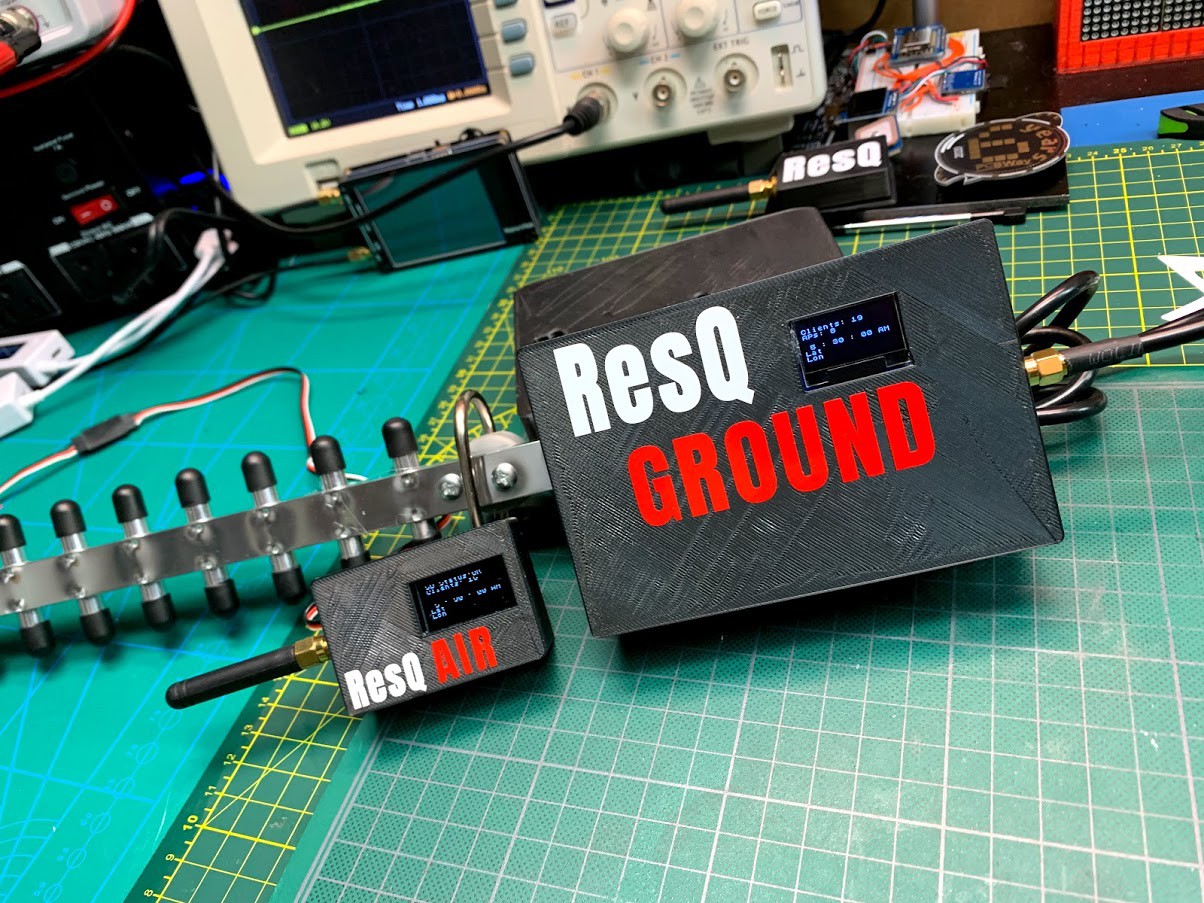
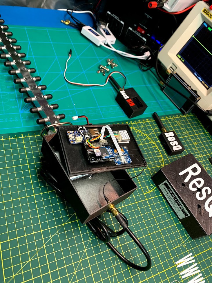
When I designed this project I decided early on that I wanted the air and ground unit to have the exact same hardware. The only difference would be the enclosure (bigger on the ground unit to contain its' own battery) and the external antenna (yagi on ground unit, small omni on the air unit to minimize weight)
Using the V1.1 PCBs I already had made I assembled the first proper ground unit while grabbing photos along the way for me to make an assembly guide doc (I will make a few kits available of this project to hopefully support making an all-in-one PCB solution/product someday). FUN :)
![]()
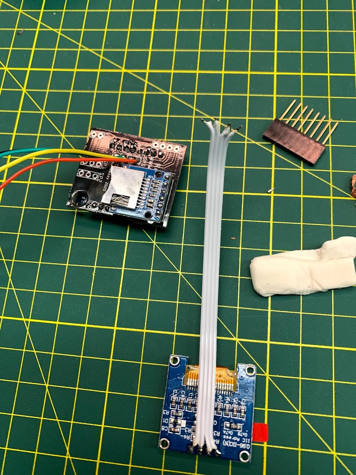
I of course forgot that most OLEDS have GND and VCC reversed to my board and hooked it up backwards AGAIN. V2.xx PCBs will correct this and align with the seemingly far more common OLED pinouts.
![]()
Oddly I had yet more problems during testing, again related to the SD card. This time they were caused by a bad card (brand new but pulls enough power to brown out the ESP). This should not have happened as I usually move the components from the breadboard directly to prototype- that way I know their history and dont introduce new problems. Always use known tested components during the early phases of your project...
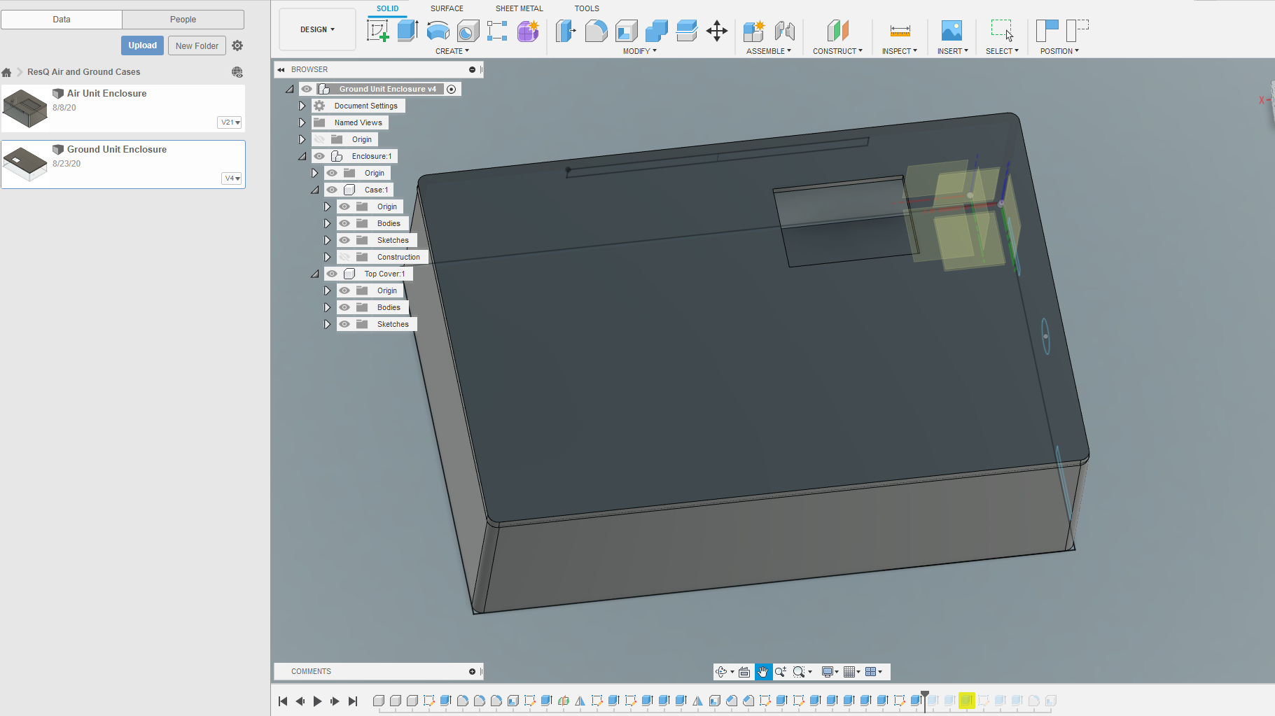
Things came together nicely and I placed them in the new ground unit enclosure design I made in Fusion 360. This just made me smile because almost the same as the electronics- I was able to reuse the enclosure CAD design too by simply adjusting the dimensions since the whole design is parameterized. Handy! If you are ever designing an enclosure- parameterize it completely. Then ANY adjustments are super easy.
![]()
I fit everything on the backside of the lid and added an Adafruit PowerBoost500 for a battery supply and charging system. If I ever do a production version I think I'd go with LiOn batteries for price and densisty. 2 18650s would likely power this thing for weeks :)
The enclosure is way bigger than it needs to be but I want to take this out in the field and beat it up for awhile before I shrink it.
![]()
As of now- Both the air and ground units are doing what I intended very very well. This is definitely usable anywhere right now at a current BOM cost under $100 bucks.
![]()
I weeen.
-
Exploiting Tourists for Fun and Test Subjects
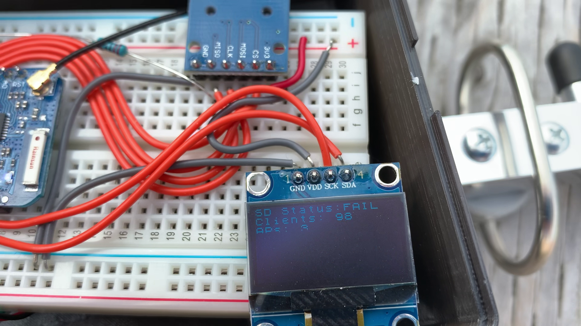
08/20/2020 at 18:10 • 1 commentSuccess! After last weeks failed field test I took the new code out on the ground unit and tried again. The SD card failed again (suspect bad card ) but my new code allowed the system to keep working as display only YAY!
![]()
Note: rolling shutter effect blocks some of the text at any given photo.
I needed a place where I could guarantee some test subjects but they needed to be far enough away to simulate a lost person-
![]()
Enter the beach where I live which even on a lousy windy day had a few dozen tourists enjoying Lake Huron :)
![]()
I pointed the Yagi out and immediately the hits started climbing.
In a few minutes I hit 98 clients and several APs detected. Of note- iphones spam new/fake MACs so this number is likely high per the subject count but that is just fine- we only need to detect them. And detect them it DOES!
![]()
At this distance I would say this is wonderful!
Video: https://photos.app.goo.gl/bdPG9w2YTUGLhg2e9
I have an LNA (low noise amplifier) I could add as a pre-amp from the yagi but according to this result- it is definitely not needed.
![]()
For simplicity of build and keeping the BOM to a minimum I will leave it out for now and design a new ground enclosure and battery system in the next few weeks. I also want to see if I can fix up the code to start a new file if the old .csv is corrupted somehow just in case it is not hardware glitches on the SPI line after all.
Thanks to the beach-goers for contributing to future search and rescue success :)
-
Schematic and Code Updates
08/16/2020 at 21:22 • 0 commentsAfter yesterdays failed field test I came home and spent last night debugging the code. Two issues caused the fail:
1. Random and persistent watchdog reboots (WDT reset)
2. SD card failure
The first was the bigger issue I have been meaning to fix for some weeks. After testing various watchdog resets in various locations in the code (manual delays trigger reset) I finally figured out it was the serial communication. I had the hardware serial at 9600 and this when dumping a big list of MACs would WDT reset. Nice.
Dont ask how long this took me to figure out. Much sad...
The second was actually a hardware problem. I did not have a pull-up on MISO for the SPI. On one prototype this was just fine but on the breadboard one- this constantly had SD card access errors. Easy fix with a 10K resistor and its now stable like a rock.
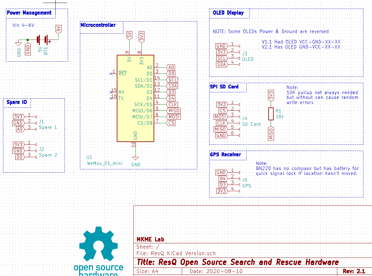
I updated the KiCAD schematic a bit today while I was adding the pull-up resistor. It looks decent to my eyes so hopefully others can follow it too.
Hope to do another field test of the ground unit tomorrow now that the code is running smooth and stable :)
I weeeen!
-
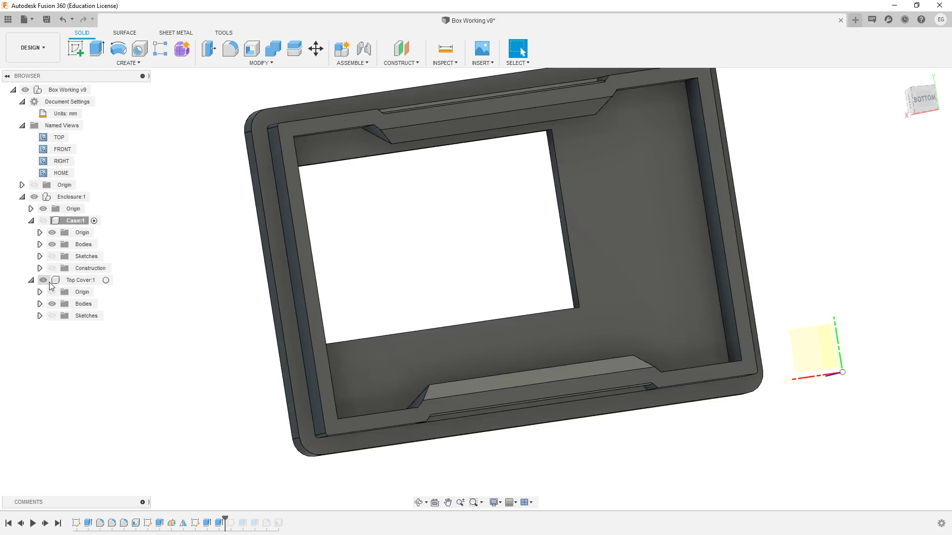
Fusion 360- We Meet At Last...
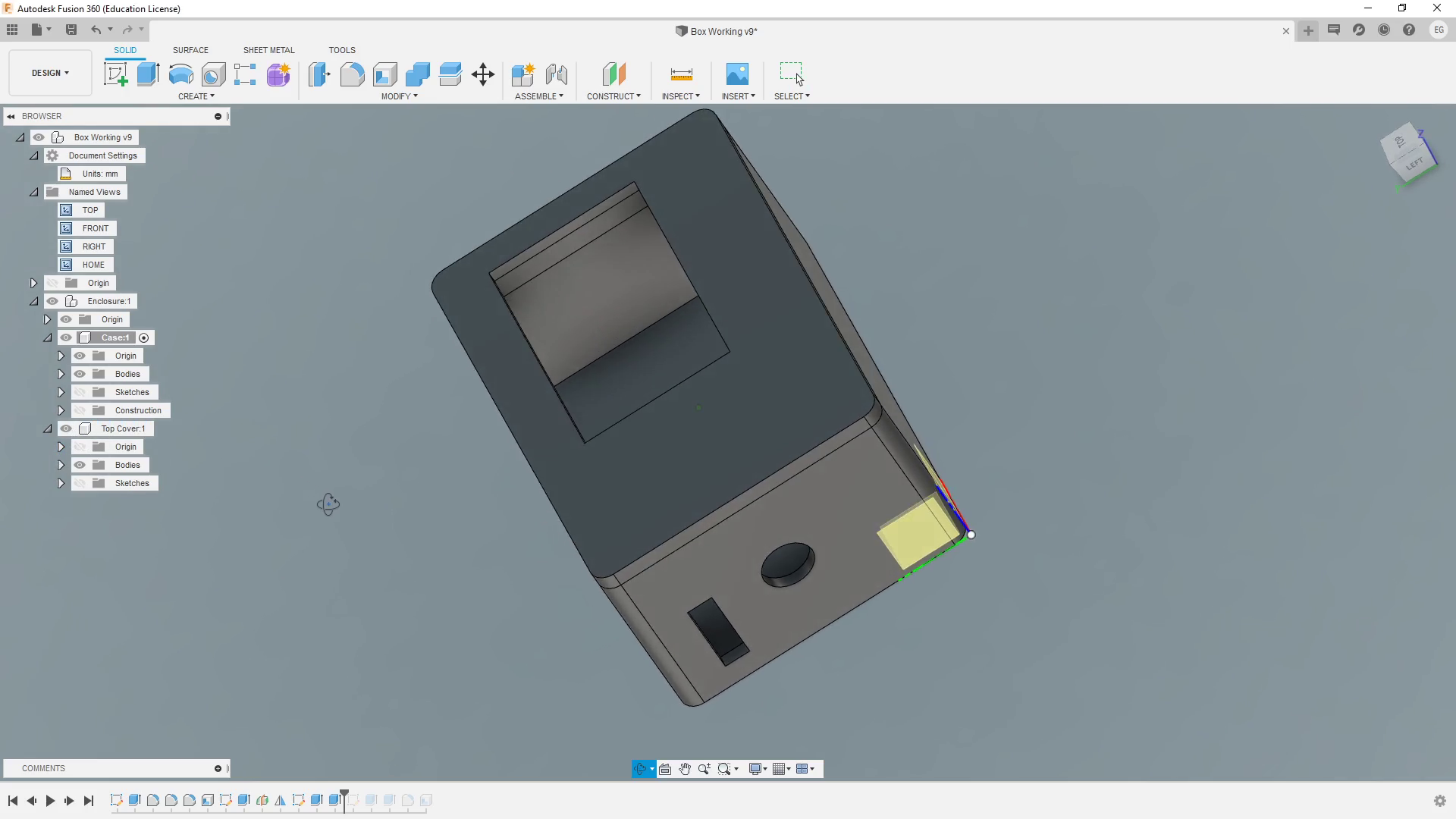
08/16/2020 at 00:17 • 0 commentsSo the OpenSCAD enclosures just weren't working out any more. I needed the air unit to be resized for the GPS to fit inside but no matter what I did- I just couldn't work with the model the way I wanted.
I found this tutorial from Noe at Adafruit and followed it to the letter (round and round for several hours as I made a couple dumb mistakes but in the end- I have a new air unit! Noe (and Pedro) you = AWESOME
![]()
The model is completely parametric with user generated dimensions so I can quickly scale/change anything I wish!
![]()
The project files are in my Git Repo and now I have a project box I can quickly use for any project forever! I just scale the dimensions as needed and do any holes with a quick sketch. So cool. I should not have put off trying Fusion360 for so long but as always- I needed a goal/project to push me to do it and learn it fairly well.
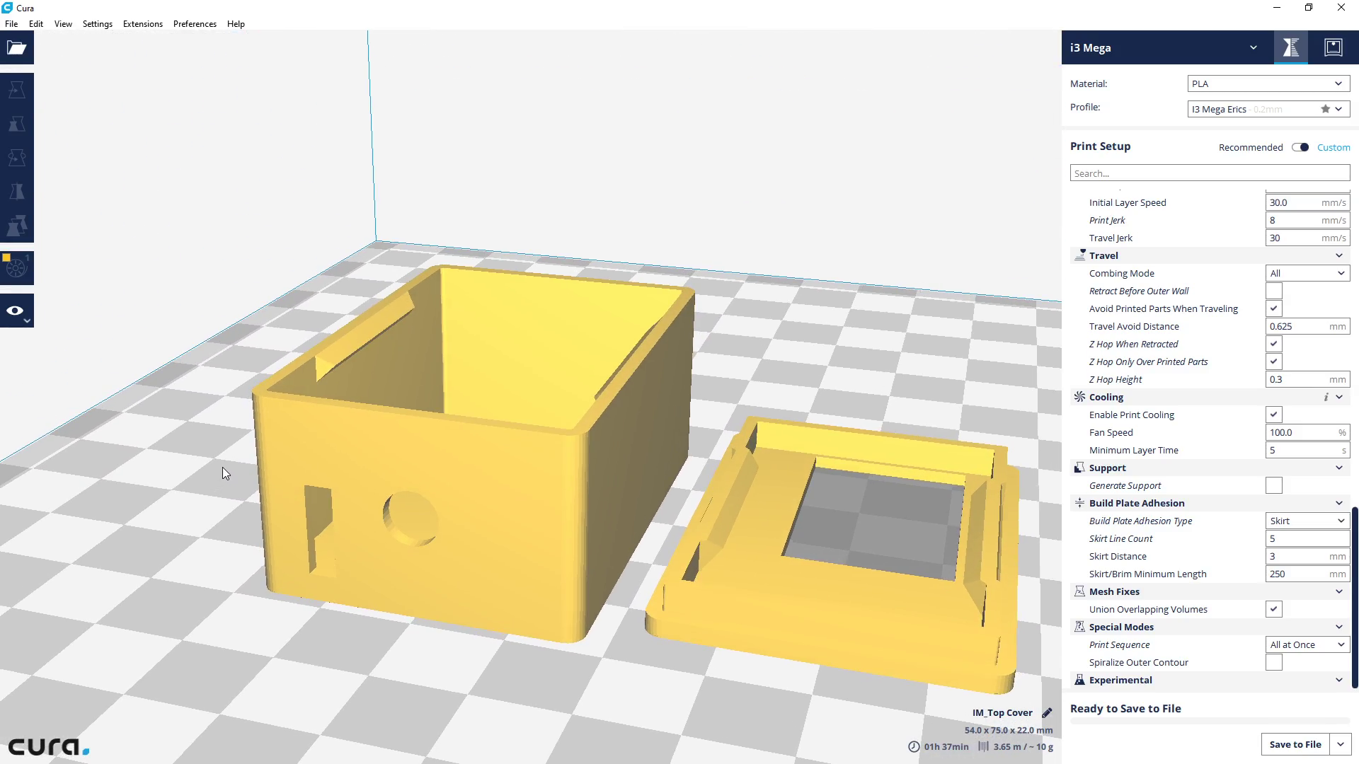
In to Cura:
![]()
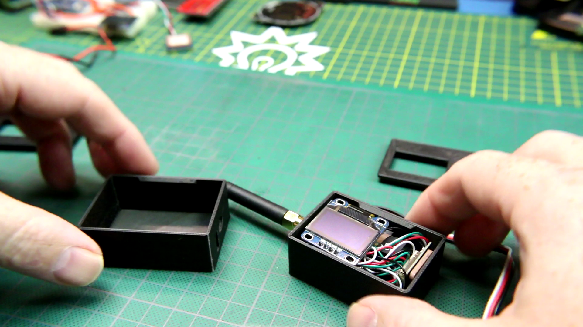
And out to the printer (i3 again)
![]()
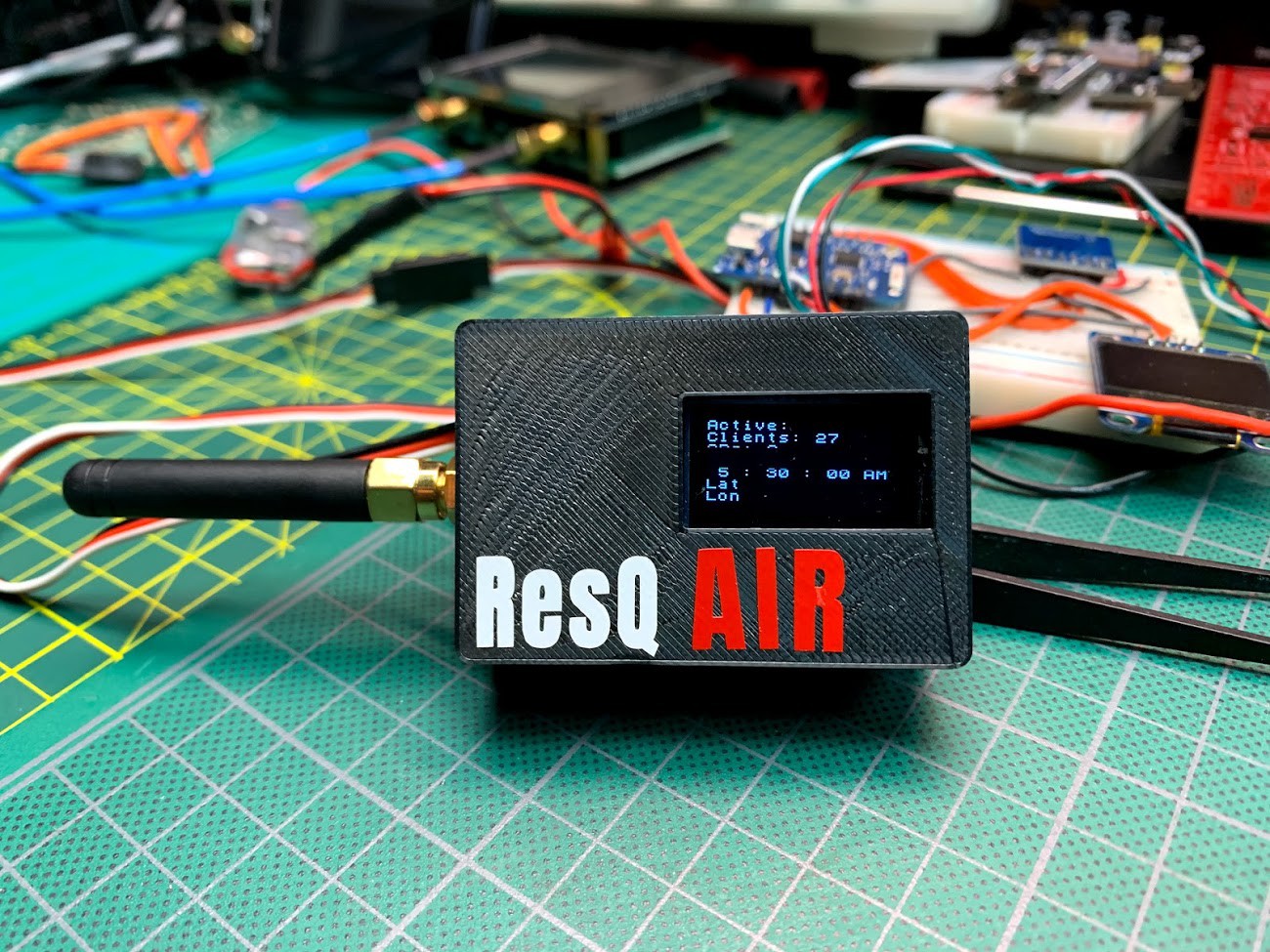
And this is what I am left with :)
![]()
I couldn't be happier with how things are coming along. Now I need to work with the code some more. I still have the watchdog resets happening periodically., SD card issue of some form and would like to add some more display functionality. Also I need to start on the ground unit enclosure/PCB assembly. So far, so good!
-
New Schematics- Enter KiCAD
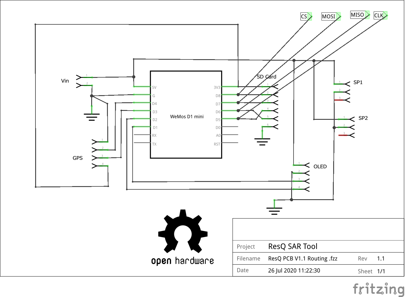
08/10/2020 at 23:27 • 0 commentsI've tested out the PCBs now and they are GREAT! for my first attempt I am super pleased that they work as intended and now reside in some developing new 3D printed enclosures. With those done I wanted to finalize the schematics and Gerbers but I just couldn't get Fritzing to play nice. For reference here is the original schematic...baaaaad
![]()
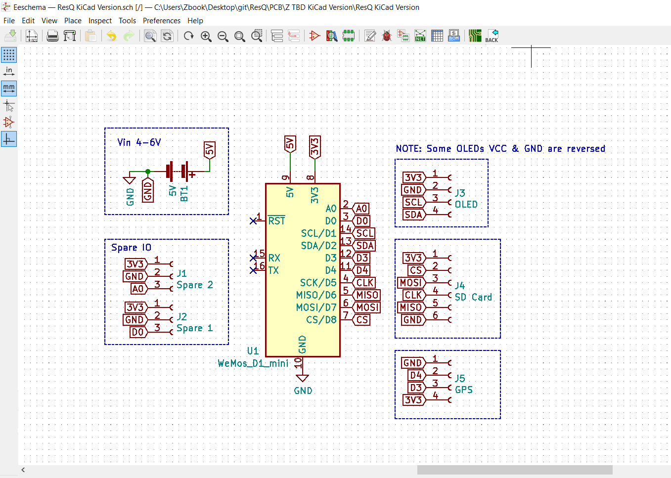
So...I finally bit the bullet and watched a bunch of YouTube videos last night. This evening I fired up KiCAD and this is what I was able to do with no previous experience in about 2 hours.
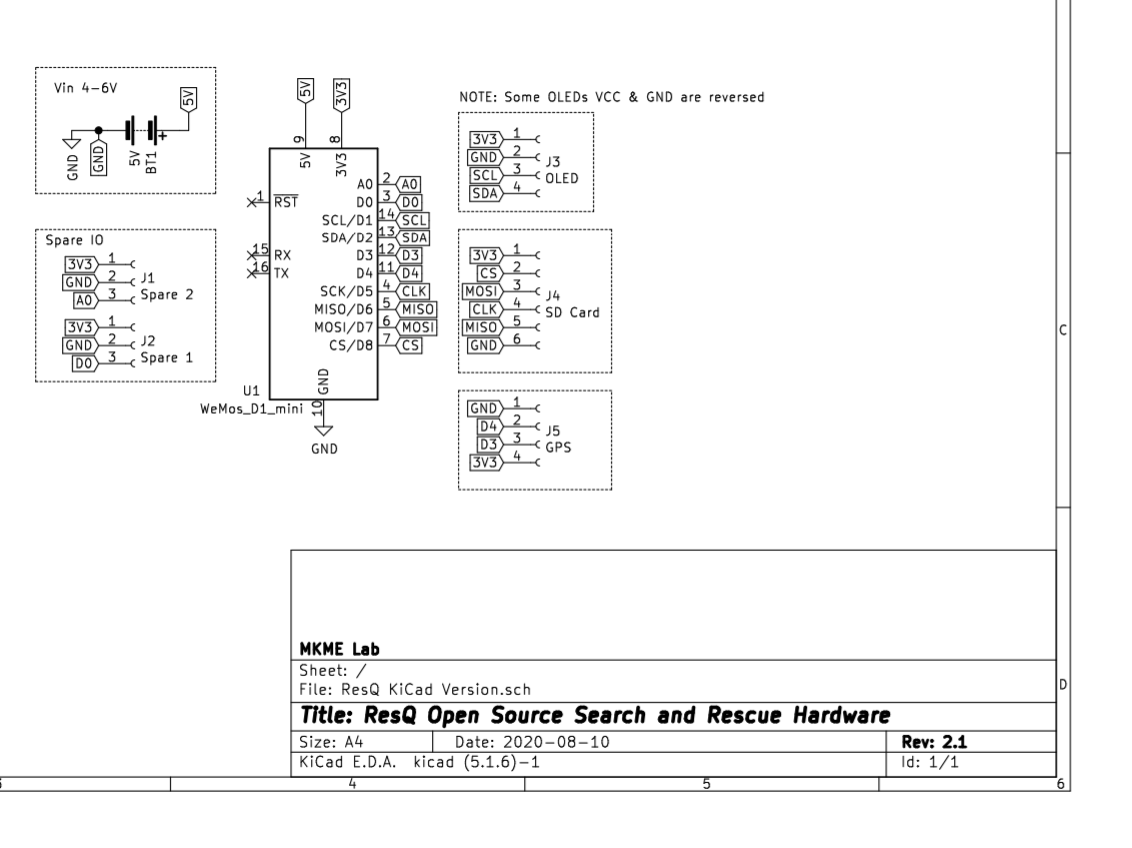
And it prints to this:
Not perfect but a heck of a lot better for sharing I think.
I haven't yet routed the new board but I did correct the previous oversight and not OLED feeds from 3v3 instead of 5V. I went over all the connections twice and it seems solid so all the files are in my Github Repo now. At least this schematic will be much better for anyone to use.
I also included the spare signal wires which are not actually routed on V1.xx boards (needs bodge wire to use them). Spares are 3V3 now instead of 5V used on V1.xx
i ween
ResQ Search and Rescue Tools
Air and ground-based tools to detect people by using their existing cell phone signature
 Eric Wiiliam