3D Printed CNC
A CNC machine made using PLA and a common 3d printer. All of the software & electronics are open source or off-the-shelf components.
A CNC machine made using PLA and a common 3d printer. All of the software & electronics are open source or off-the-shelf components.
To make the experience fit your profile, pick a username and tell us what interests you.
We found and based on your interests.
IMG_1272.jpg0.50" dual shaft holder for 2040 extrusionJPEG Image - 656.96 kB - 03/30/2021 at 00:35 |
|
|
IMG_1270.jpg0.50" dual shaft holder for 2040 extrusionJPEG Image - 364.15 kB - 03/30/2021 at 00:35 |
|
|
IMG_1271.jpg0.50" dual shaft holder for 2040 extrusionJPEG Image - 420.73 kB - 03/30/2021 at 00:35 |
|
|
IMG_20200521_115445_914.jpgJPEG Image - 273.85 kB - 06/05/2020 at 04:05 |
|
|
IMG_20200520_190154_862.jpgJPEG Image - 368.92 kB - 06/05/2020 at 04:05 |
|
|
Finally got some more CAD work done and made a 0.50" dual shaft holder. It mates to the channels in the 2040 extrusion and shafts will be press fit. Next revision will take in consideration where the motor and shaft placement. The big benefit here is utilizing the 3d printer precision to align the shafts perfectly. Ideally they would extend 10mm into the frame.
This feels like a slight pivot, but I will do my best to keep the project true to its roots, affordable and 3d printed.
I dug up an old anet a8 metal frame, AM8. Initially I thought extrusion wouldn't be good for this, but it was merely the 8mm rods that were insufficient. I plan to use the 1/2 and 3/4 steel tubes (*are tubes suitable or must it be rod?) and bronze bushings. I found inexpensive $1.50 tube holders that will work as shaft holders and bearing holders. Another idea is to do a press fit for the shaft into the aluminum, but I don't think I can drill that accurately. I'll still drill the frame a bit, but it'll likely just be to extend the rods and be held with a 3d printed rod holder. There is also a possibility of brazing everything rigid. One thing I noticed about aluminum extrusion is barely anyone is using an anchor fasteners. Mostly through holes and 90* fasteners and I suspect the anchor makes it a much more sold structure. Avid CNC uses anchor fasteners for their machines. I'm going to use them on this. Perhaps even test the difference between anchor fasteners and other options.
The bronze bearings look like theyre going to work. I got a set of 1/2" and want to get some 3/4. I'm happy this is working because I don't have to use v-wheels.
3/4" Pex tube seems to have a lot of potential for me. Initial observations: it can be machined out to fit either 3/4" 0.750" which is widely available, as well as .706" which is 1/2" conduit. I want to stay true to the build and keep it cheap/affordable so will pursue the conduit, but very optimistic for PEX in 1/2" and 1". I see 1" being good and bigger/better than 3/4 but the widely available conduit and 3/4 pex off the shelf keeps them a main focus. The PEX ID is 0.671, I bought a 45/64 drill bit which is .703, and then I got an 18mm reamer which is .708. I also got an adjustable reamer which ive never used, so that should be interesting. Another neat part of using the 3/4 pex is its outside diameter is 7/8 0.875 and it plays well with 7/8" tooling.
I screwed down the linear shaft and im a little more encouraged by the alignment. Round shafts have a tendency to turn and will cause racking problems. Shafts need to be fastened down, or held. I just screwed a metal screw through the side.
I have decided to change gears slightly and focus on a fixed gantry build similar to a microcarve cnc or sienci mill one. I like the box aspect but the construction was terrible. The millright m3 also suffers from poor construction.
Panels need to be fastened VERY SECURELY. Avid cnc uses barrel nuts, and microcarve uses a plate bushing. A 3d plate bushing could work. Perhaps for ease of use keep outside profile rectangle and just mill a pocket to receive it. Either 3d printed or cnc wood plate. Idea is more pocket depth/ interference fit, plate inside and outside? Microcarve has EXCELLENT construction and I want to merge that with the sienci box idea.
The other idea is to use c-beam or other v-slot as the main gantry for the cnc box. Print NC has shows tapping/ prepping 2x3 steel beam isn't so bad but with a novel 3d printed marker/jig it can be manipulated intelligently.
In terms of keeping this cheap the ideas I to pursue:
- 1/2" conduit pipe with pex bearings
- 1/2" round steel tubing with bronze bushing
This is probably the most sure fire, cheap build.
Goal is 100ipm in aluminum at 1/8" depth and 1/4" bit.
Will either be 8mm lead screw, or belts, nothing nicer.
3d printed bearing blocks.
Aside, the Root cnc looks cool. Classic v-bearing formation using a nice 3d printed chassis. Square tubing is the way to go. I was wondering if mini v wheels, or just the bearings would be a good option on square tubing. The problem now is, its a very slippery slope to Chinese mgn rail.
I'm trying to settle on a design, but I was advised to try all 3. The 3 designs are 1. round linear bearing (current) 2. Y- Linear bearing 3. U Groove wheels. Im almost ready to print a u groove wheel for a 1/2 emt, and 5x16x5 bearings. I found 8 x 16 x 5 are also cheap bearings that should be suitable for the Y linear bearing.
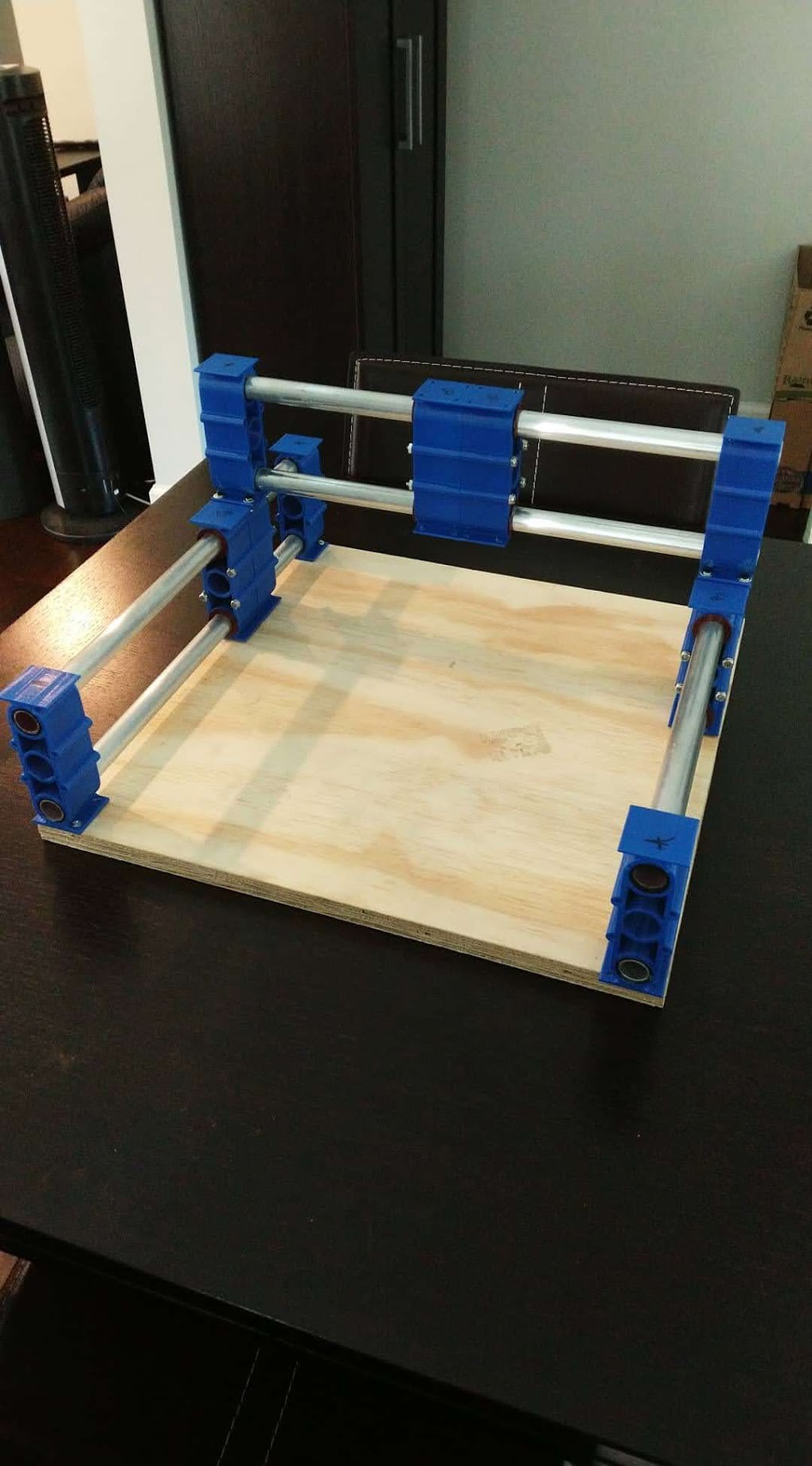
Drilled and bolted the frame. Cut the sub-board crooked :(. Getting binding and all sorts of twisting. I could get some movement for the sake of it, but this is definitely making it to a beta version. Need to spend more time in CAD. I do have parts for a brushless spindle on the way.
Finally got the print settings dialed in for the rod holder. In the future i'd like to test PLA as a bearing material. I tried nylon, but it was rather soft. Igus has some special filament that seems interesting.
This design was so that I didn't have to "dial in" on a 1mm print nozzle. I could get the majority of the structure there and print a more precise bushing with a 0.4mm nozzle.
Finished a 9 out of the targeted 12 blocks for the minimum needed to move all the axis. Next step is making rod holders.
Create an account to leave a comment. Already have an account? Log In.
Become a member to follow this project and never miss any updates
 Myles Eftos
 Marc Schömann
 Sebastian Lenartowicz
 Russell Munro