Fabian
-
The main shaft coupling
07/13/2020 at 12:41 • 0 commentsWhile I'm working on the adjustments for the pitch actuator, I thought it would be time to present how I imagine the coupling between the main shaft and the generator.
In principle, I didn't invent anything new here and was mostly inspired by the principle of well-known shaft couplings.
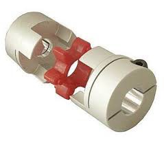
You can see the well-known principle in the following picture:
![]()
It consists of two parts that are firmly mounted on the respective shaft part and are inserted into each other. A rubber buffer inserted between them dampens any vibrations that may occur.
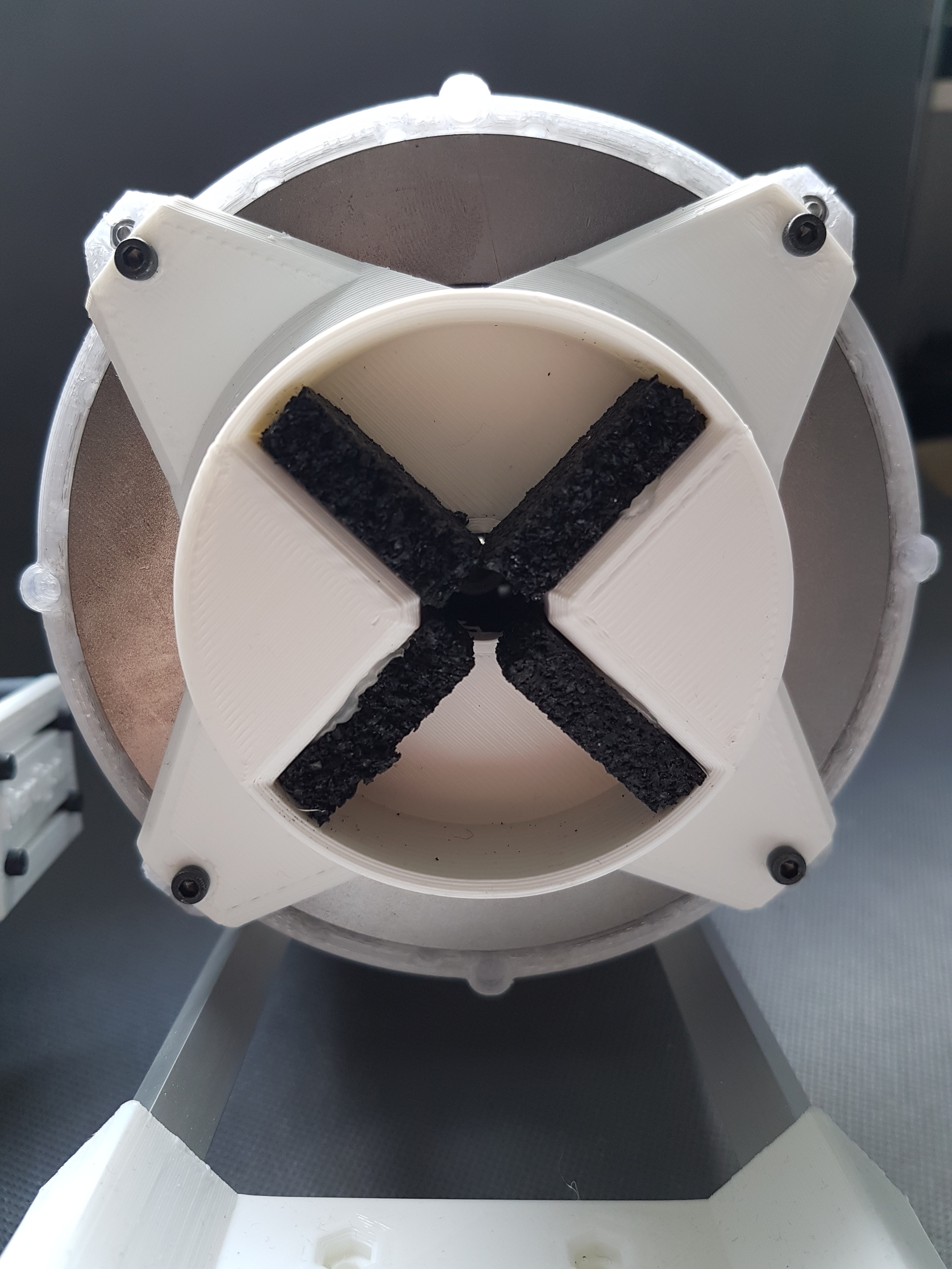
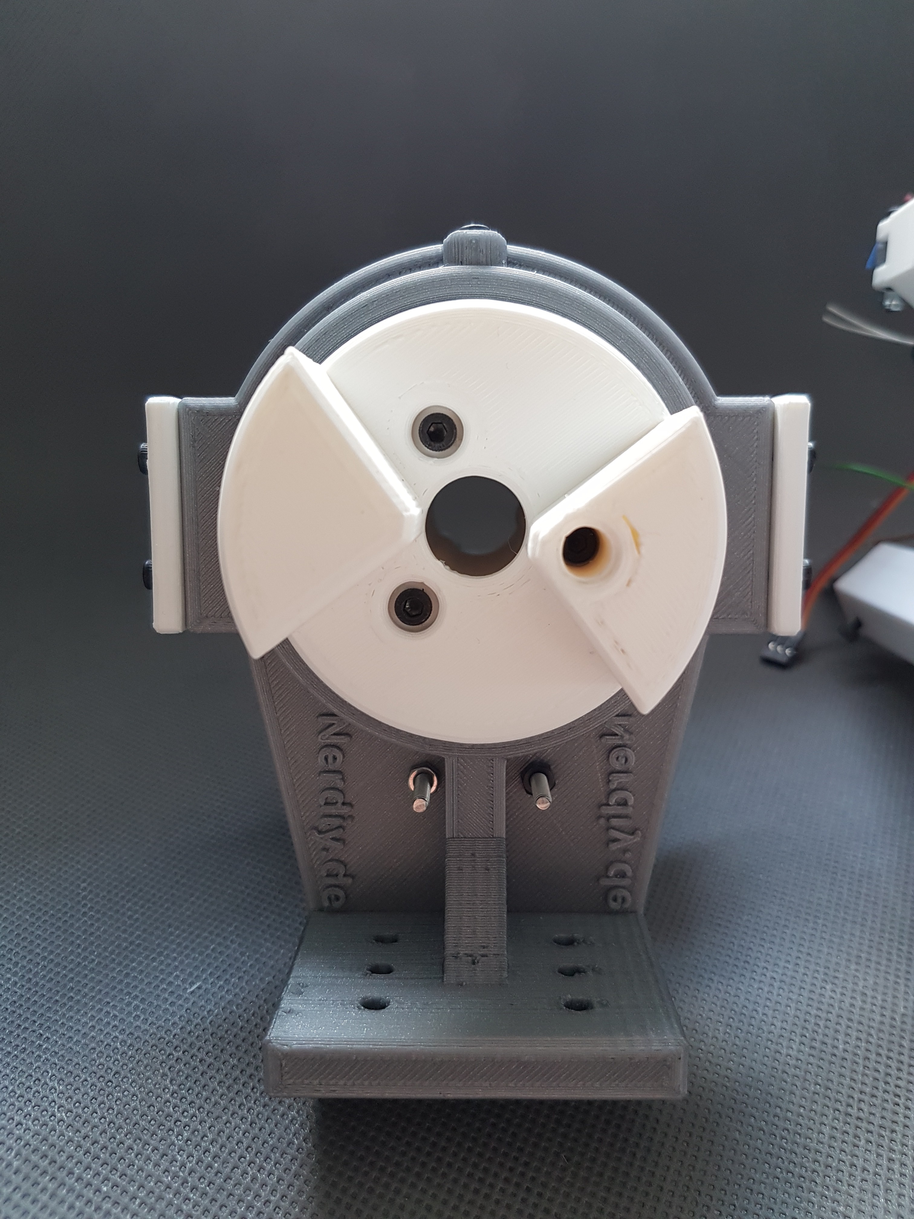
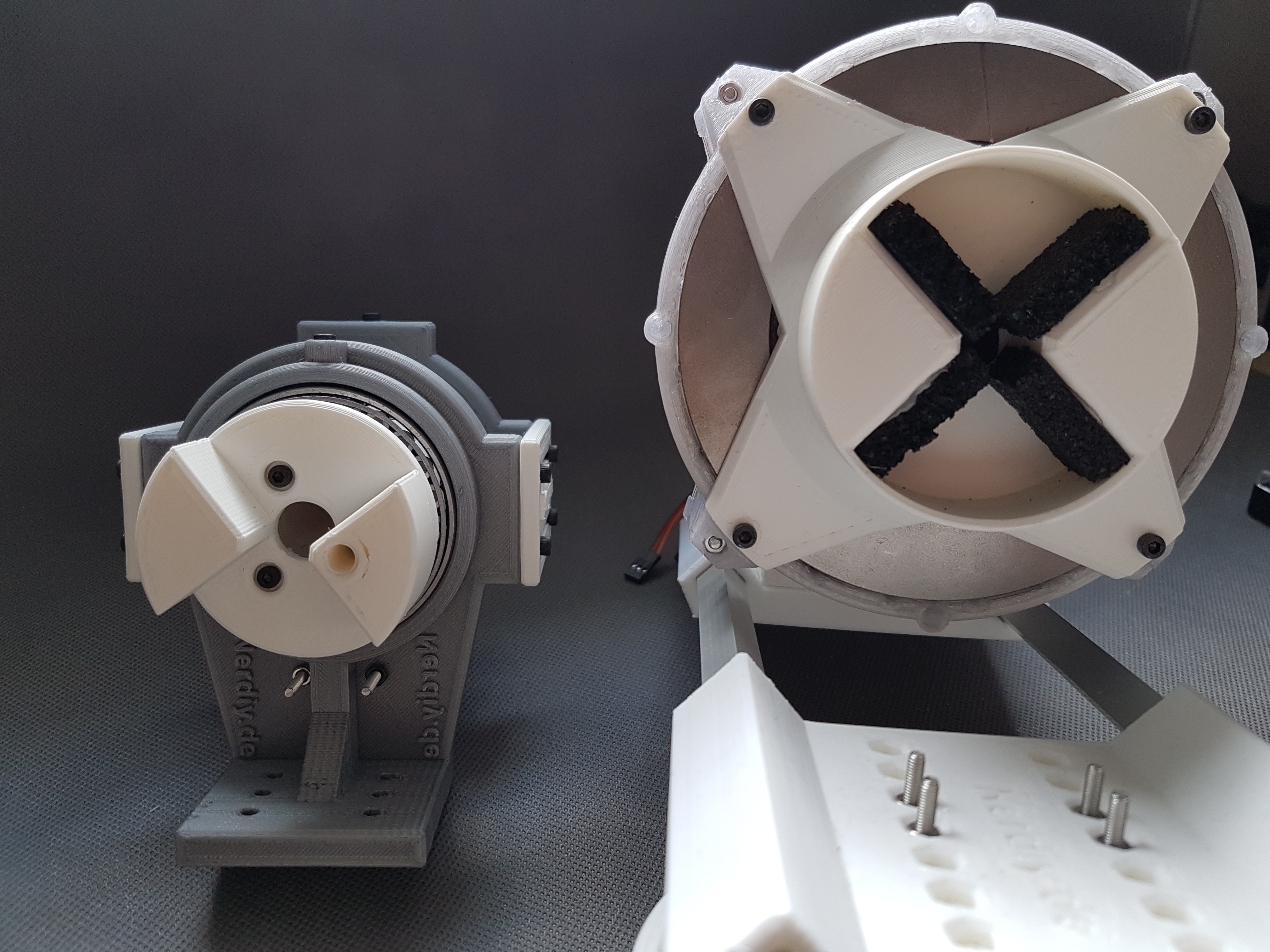
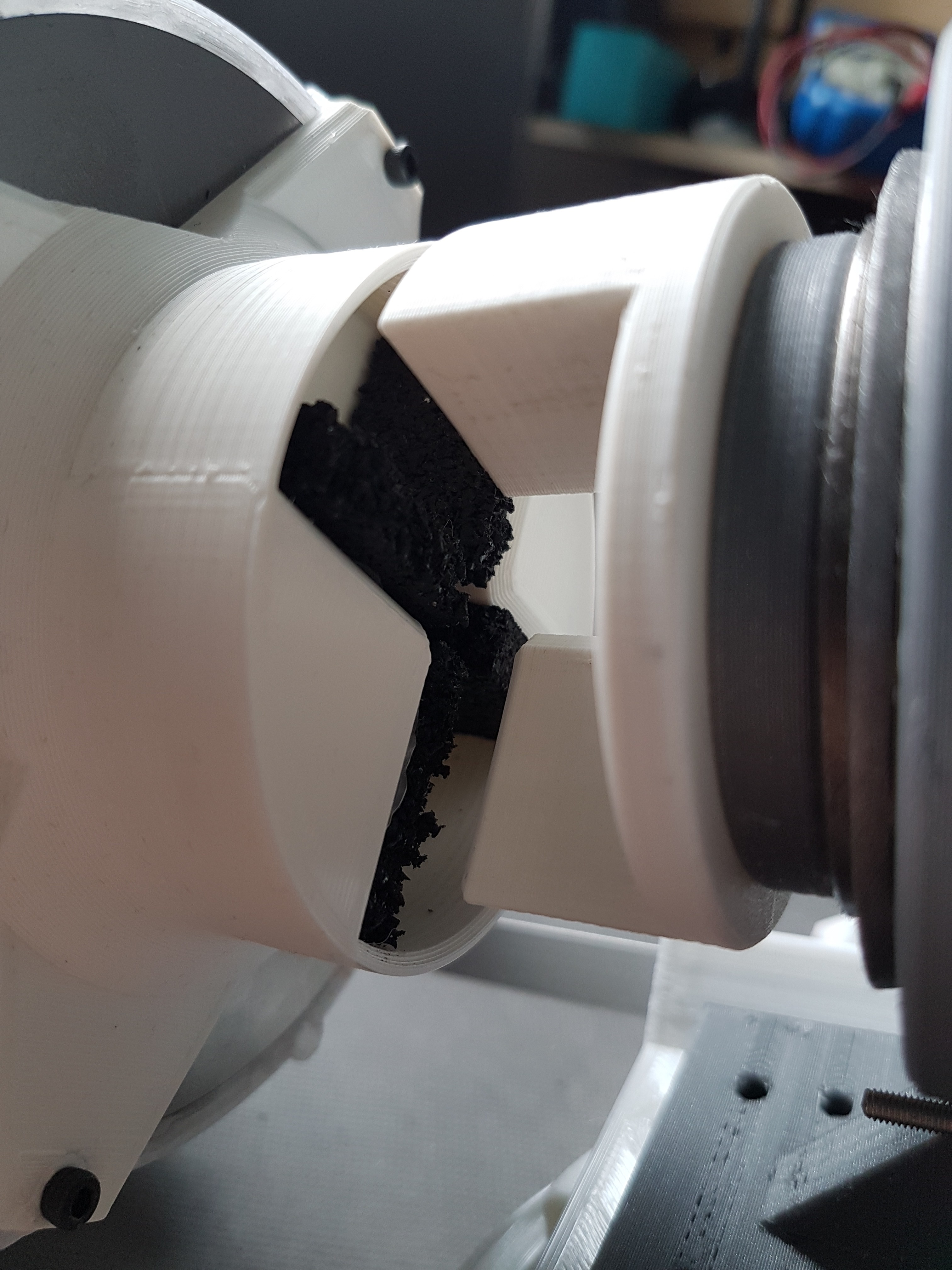
And here is my version of this type of coupling. I used cut pieces of a rubber mat as a damper. Unfortunately, it is very stiff. Maybe I will exchange this for a softer material. Otherwise, so far this principle seems to work well. :)![]()
![]()
![]()
![]()
-
The "pitch actuator" in action
07/05/2020 at 14:04 • 0 commentsSo, I successfully tested that the current design for the pitch actuator was a failure. :D
The pitch actuator is the part that moves the threaded rod back and forth, which in turn adjusts the angle of attack of the wing.
The construction itself works exactly as I hoped (see video). Unfortunately, the stepper motor used (the well known 5V stepper 28BYJ-48) is clearly too slow to allow a quick adjustment of the angle. At first I thought "Oh it's not that bad" because it wasn't really meant to have to quickly adjust the angle of attack anyway. After the first complete test run, however, I noticed that a complete trip from end position to end position takes almost ten minutes.
That is a little too long for me. :)
But I already have an idea for improvement. At the beginning I had planned to install only two limit switches for the respective end positions and to determine the position in between by counting the step motor steps relative to the end positions. (Similar to the system used on 3D printers) In the meantime, however, I had the idea of making it possible to query the current position of the threaded rod using a sliding resistor.
This has the practical advantage that I can also use a normal DC motor (probably a "Reely R140") instead of the stepper motor. This creates a significantly higher speed (14000 rpm) and thus higher adjustment speeds. At the same time, the current position can be tracked using the sliding resistor. :)
Now that I know that the design works in principle, I just have to change the motor bracket a bit. :)
Please note that the video below is 20x faster than the original.
-
First design of the pitch control actuator
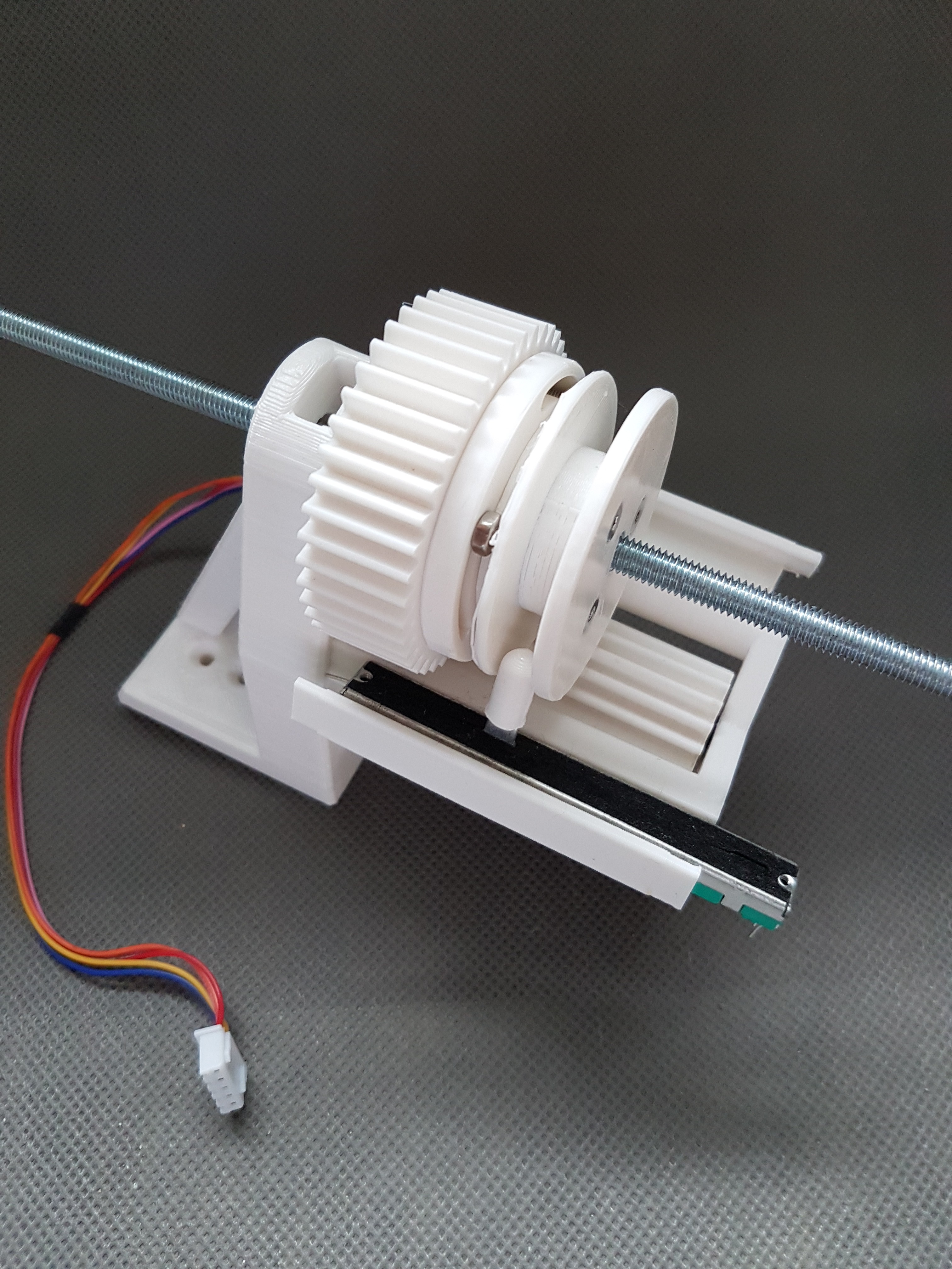
07/02/2020 at 15:07 • 0 commentsIn the last few days, I have completed a first design for the actuator, which will be used to control the pitch/angle of attack of the wings.
Since I recently found some cool tools for designing gears (https://hackaday.io/project/172445/log/180101-test-stand-for-the-nerdiskerator) I was able to use them here too.
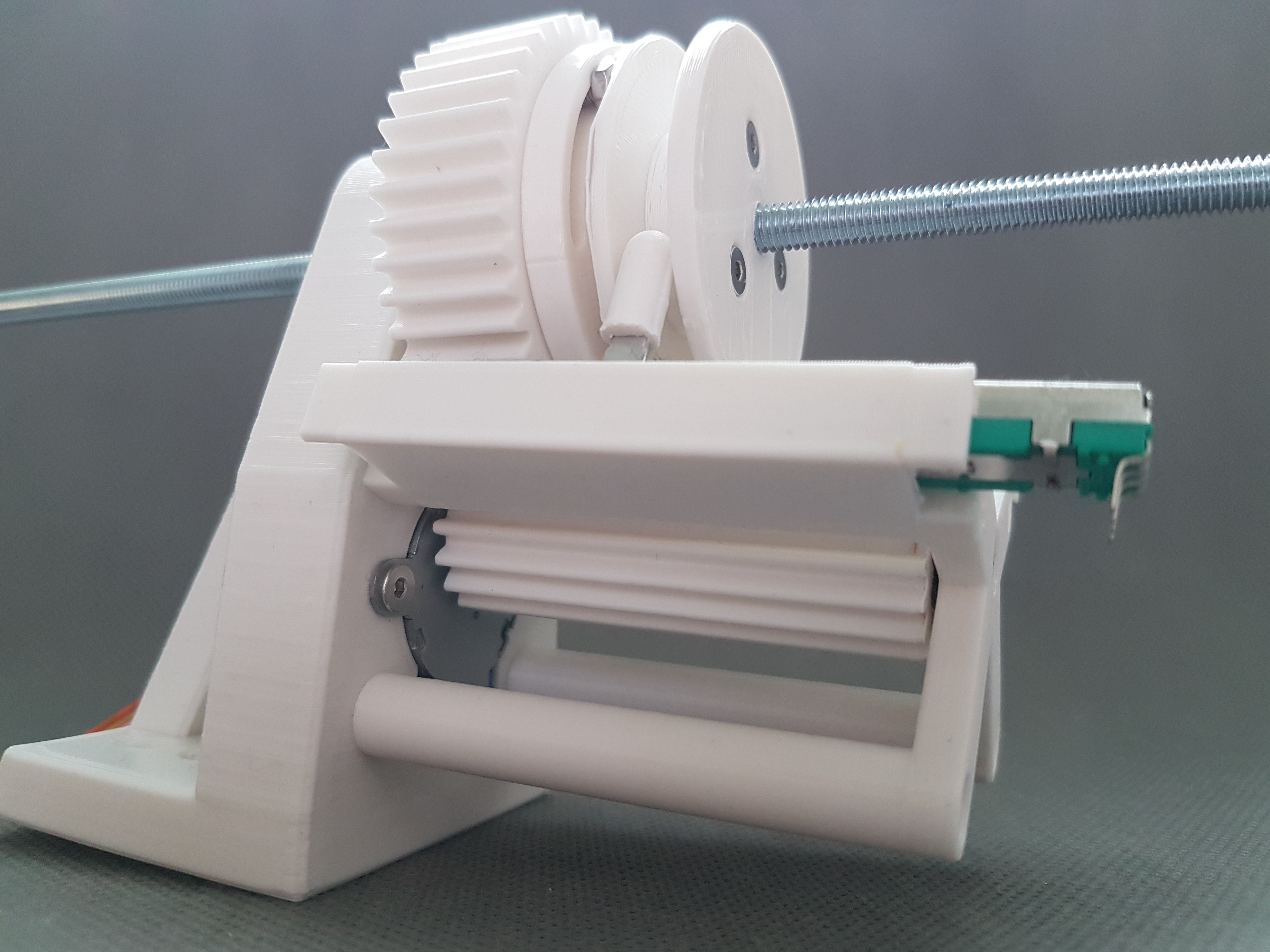
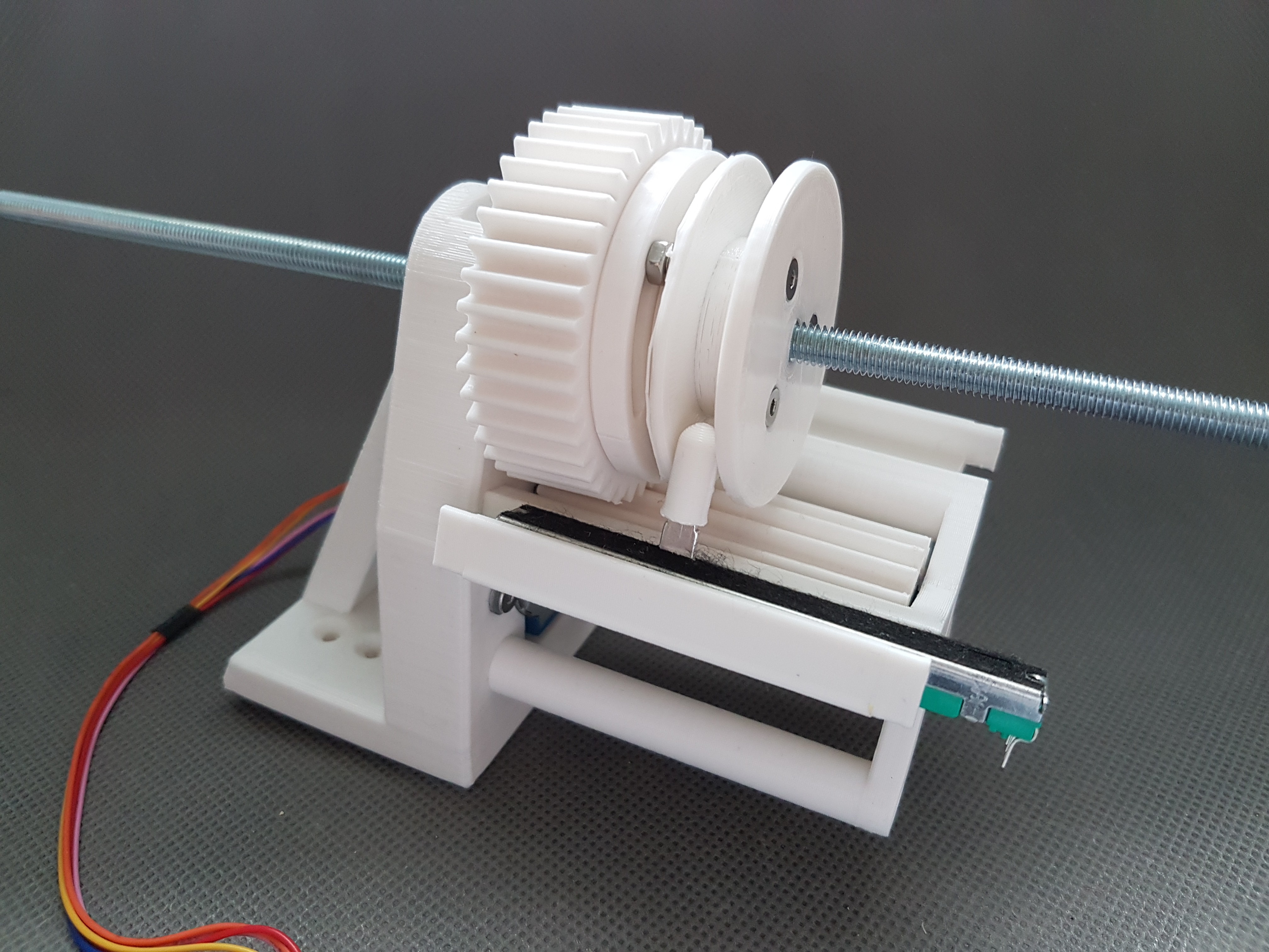
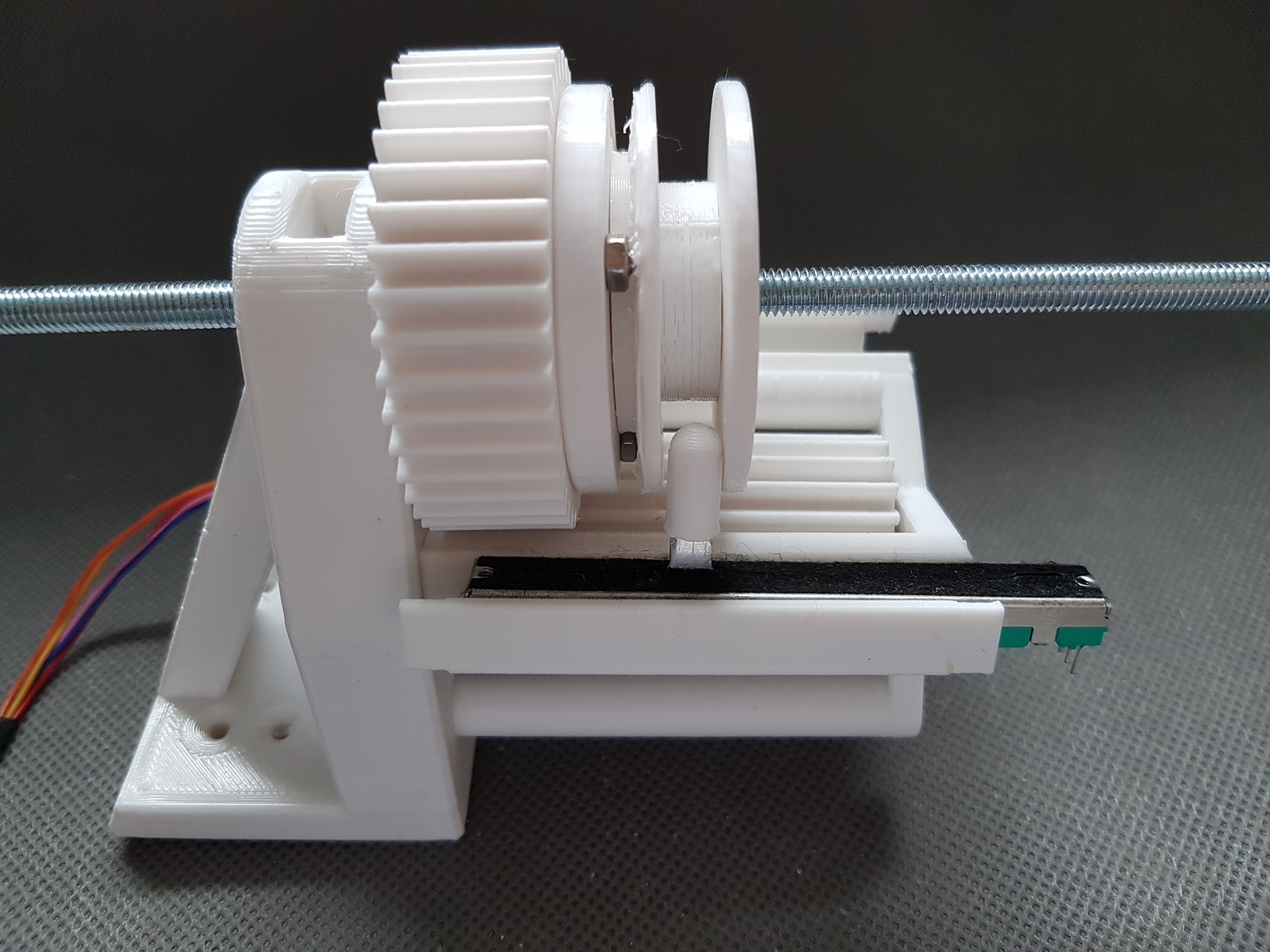
A small gear is mounted on the axis of the 28BYJ-48 stepper motor. This then drives the larger gear which is firmly seated on the M6 threaded rod.Since the threaded rod is mounted in a nut, which in turn is permanently installed in the holder of the stepper motor, a rotation of the threaded rod will hopefully result in a forward or backward movement of the threaded rod.
Hopefully this should adjust the disc in the hub of the rotor and thus the pitch of the blades. :)So that the current position of the M6 rod can be measured, I have installed a sliding resistor so that it is taken along by the back and forth movement of the gear/rod. So you would have to be able to use an ADC later to measure the position of the M6 rod.
Everything a little difficult to describe. So here are a few photos. As soon as I have a complete set up, I will also post a video. :)
![]()
![]()
![]()
![]()
-
Why (I think) a new main shaft mount is needed
06/24/2020 at 13:53 • 0 commentsThe last two weeks I have been working on redesigning the main axis of WinDIY. The old axis worked, but had two problems.
The first thing, it was/is quite loud. I used angular ball bearings because they are actually perfect for absorbing forces in the axial and radial direction. Conveniently/unfortunately, the gap (between the bearing components) is adjustable with these. That means you can decide by the dimensions of the housing parts how close together the individual bearing parts are.
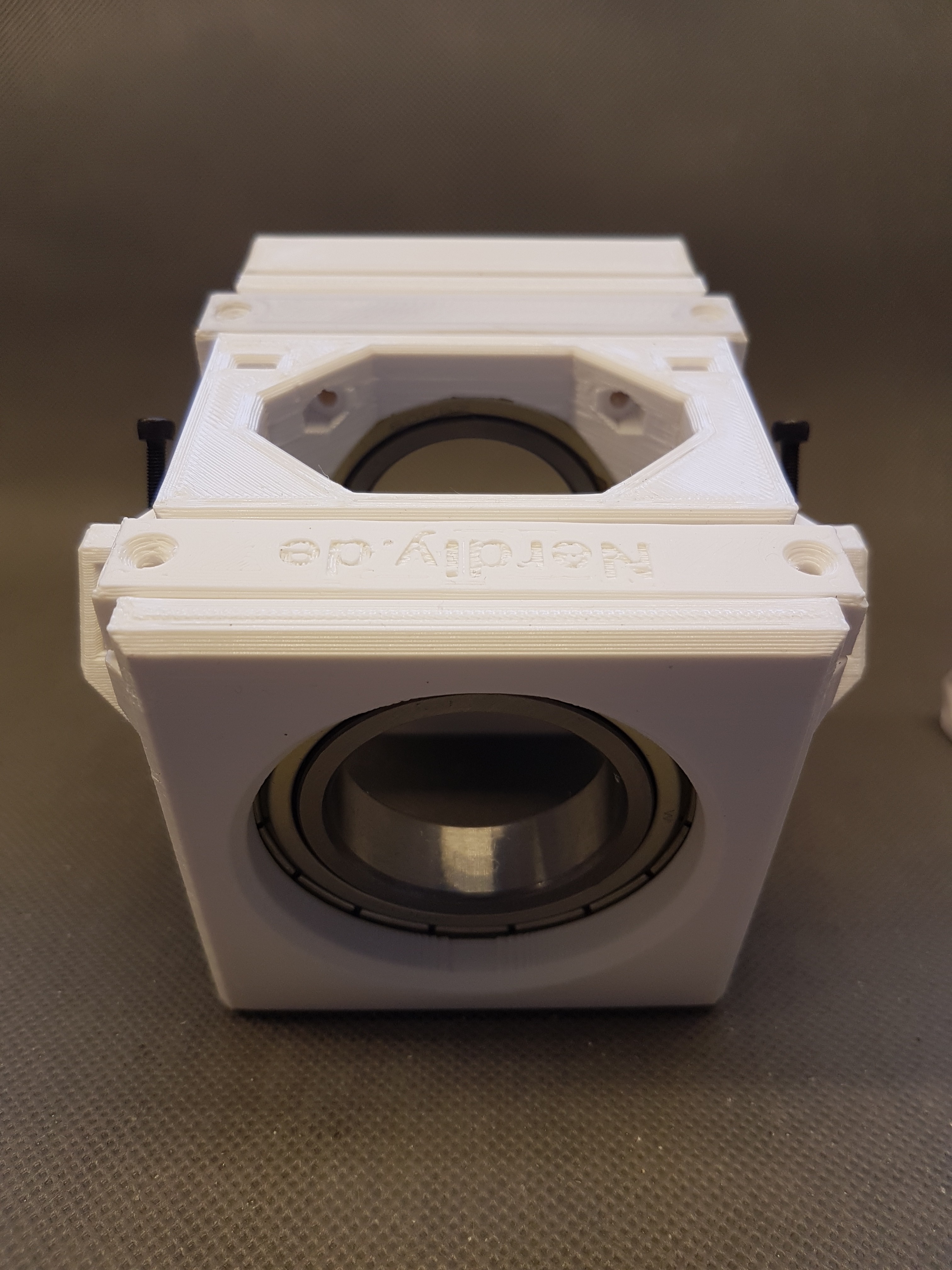
Unfortunately I never managed to set these properly. (Maybe I also lack the experience with these kind of bearings.) Also in order to not make the structure even more complicated, I decided to replace the angular ball bearings with radial bearings. These can take about 10% of the radial load in the axial direction. So if you install a radial bearing that is oversized accordingly, it should also fit with the forces in the axial direction. :)
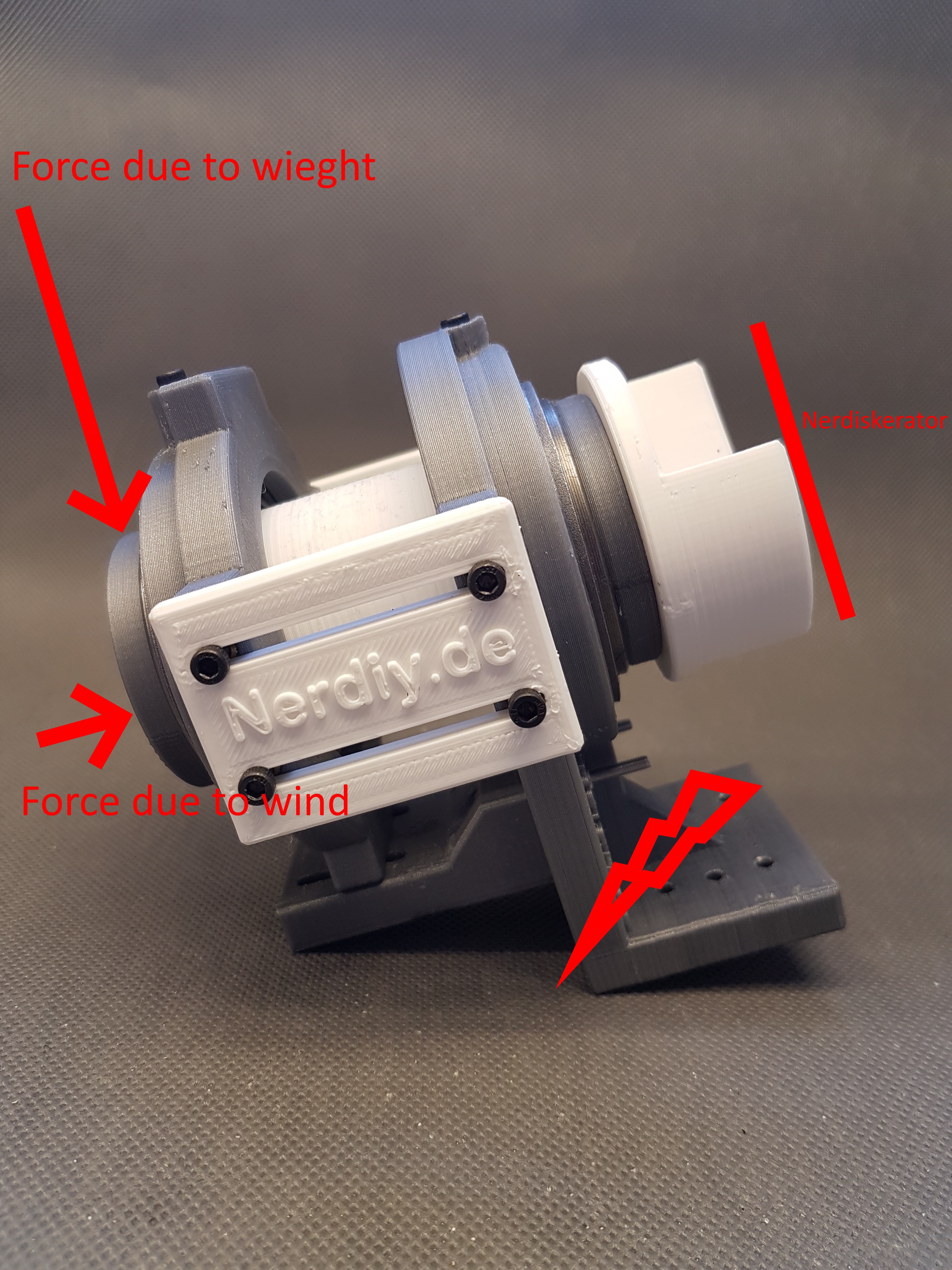
(And I am sure that I will find another use for the - now remaining - angular ball bearings.: D)The second problem is that the old connection between the shaft mount and the rest of WinDIY consists of 3D printed parts. I suspect that this will not last in the long run because this point is exposed to changing forces from the front (due to wind pressure) and the weight of the wings and hub.
I tried to show what I suspect in the picture. The whole 3D printed structure will experience forces in the direction of the arrows. Plus vibrations from the components, which may not be perfectly balanced. All of these forces are ultimately dissipated into the rest of Windiy 's structure via the spot marked with the flash.
Therefore the flash marks the point where I assume that this structure will not last very long.
That's why I decided on a redesign, which you can see below. :)![]()
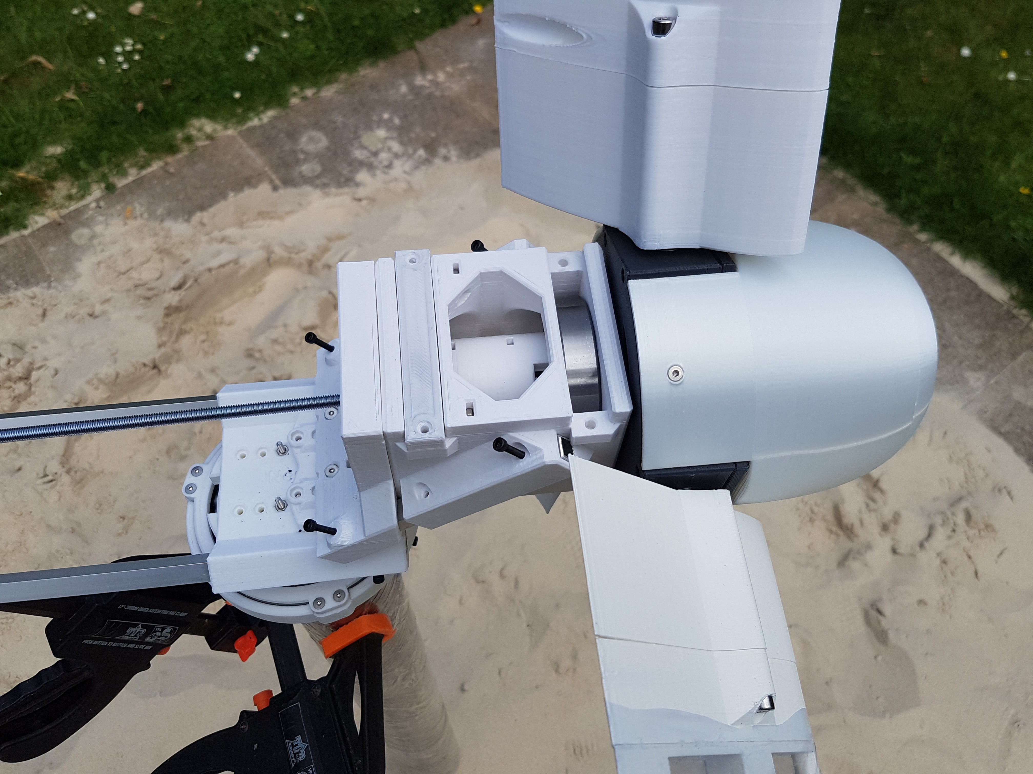
The new design
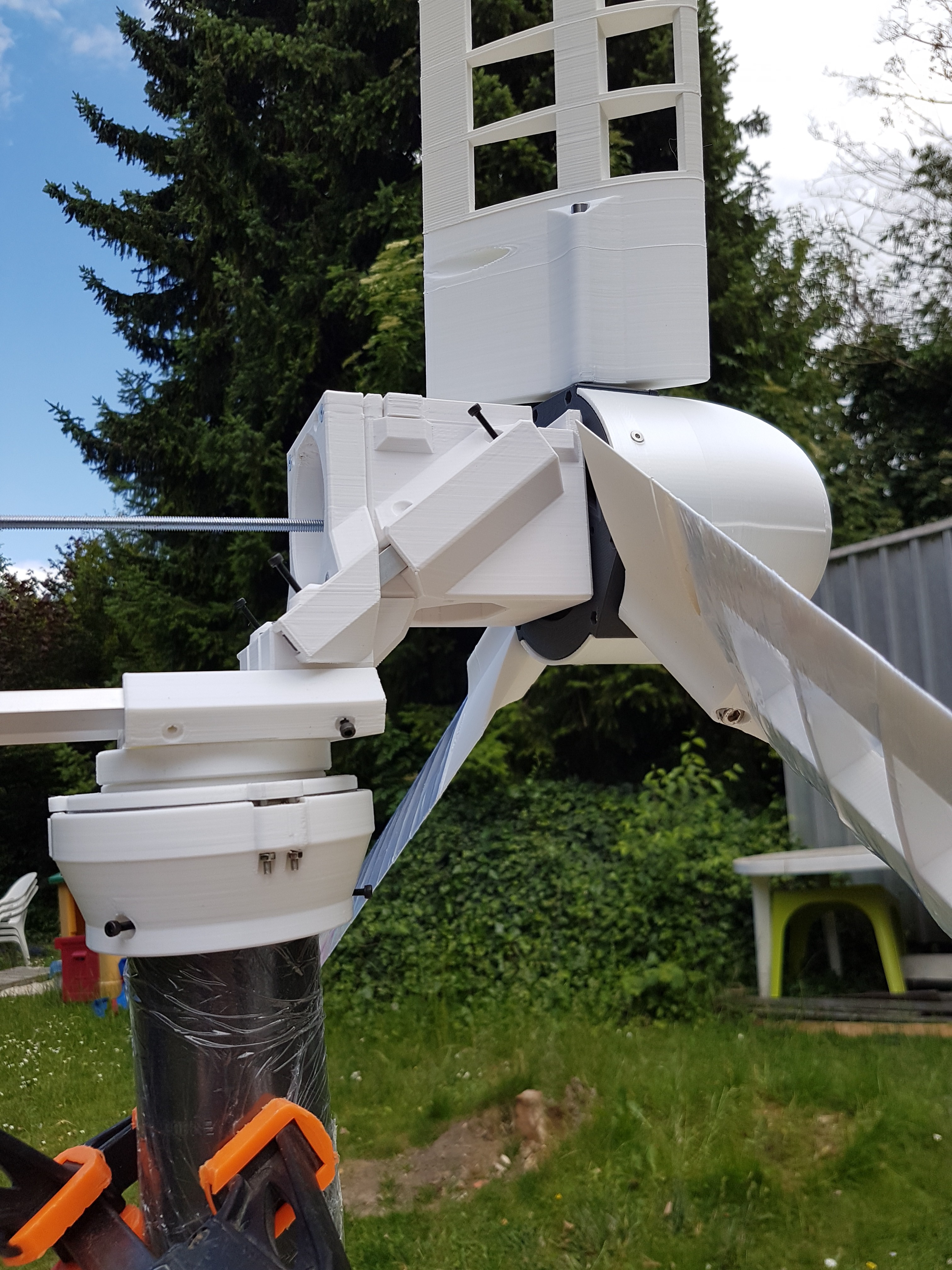
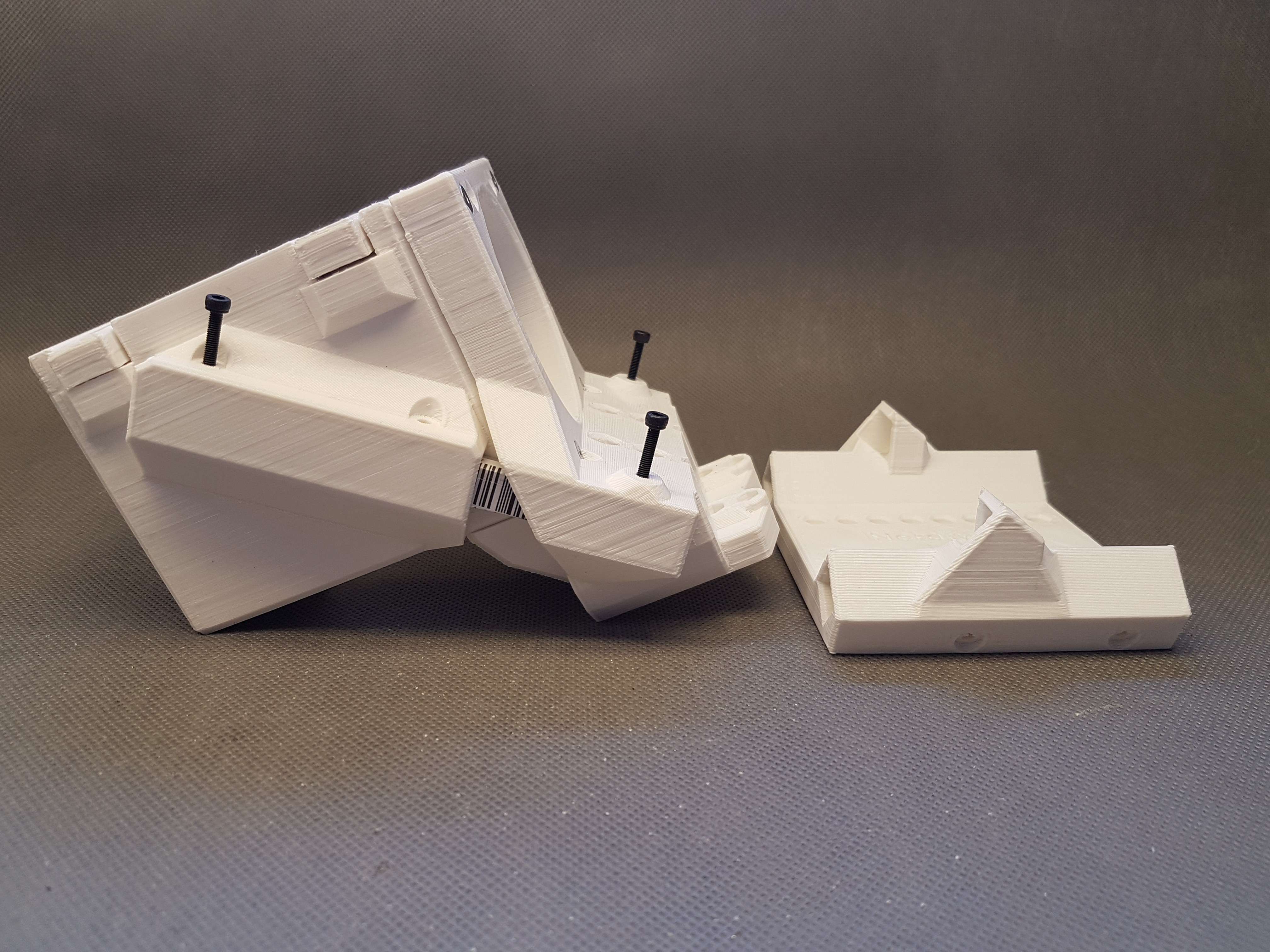
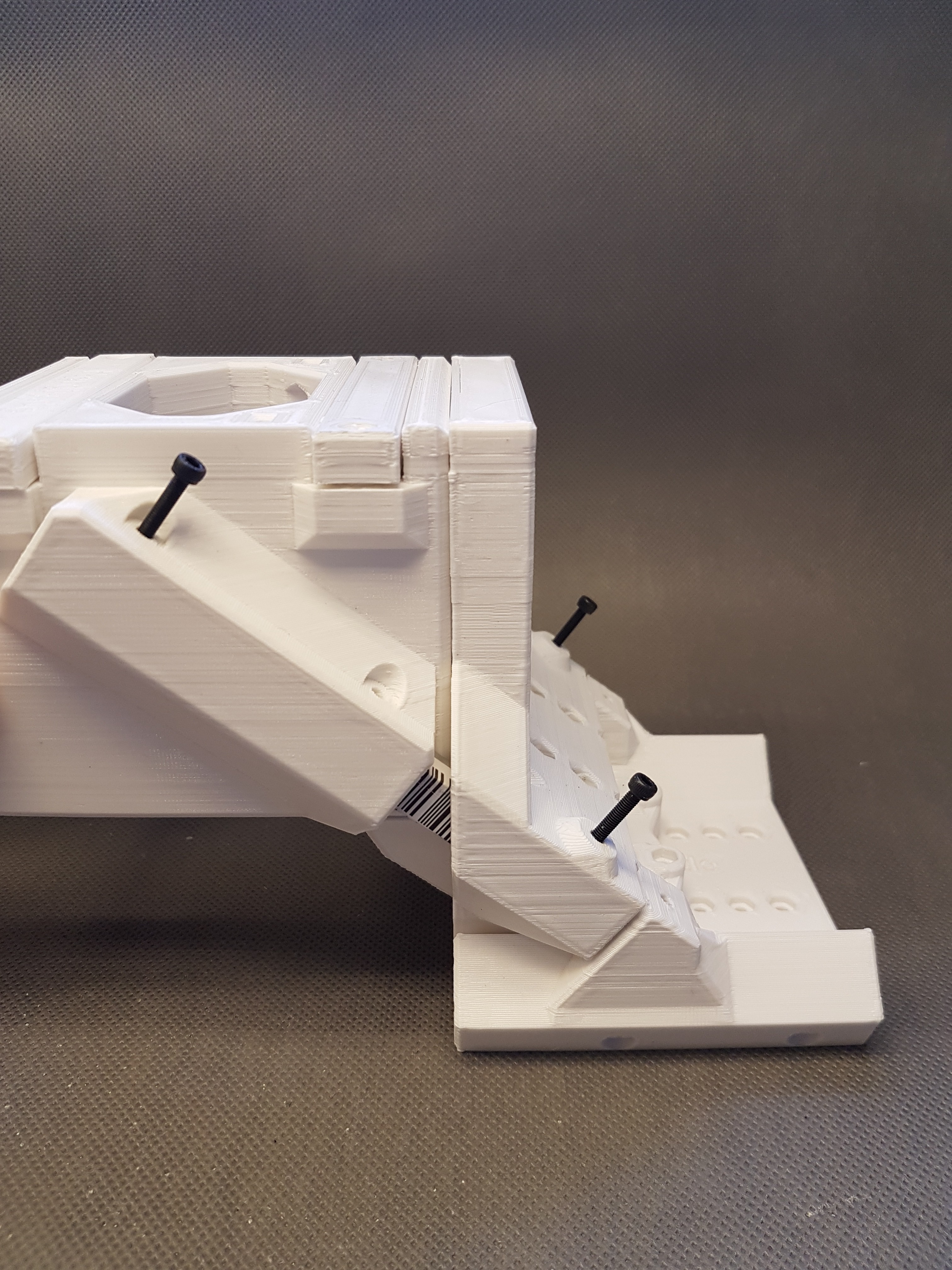
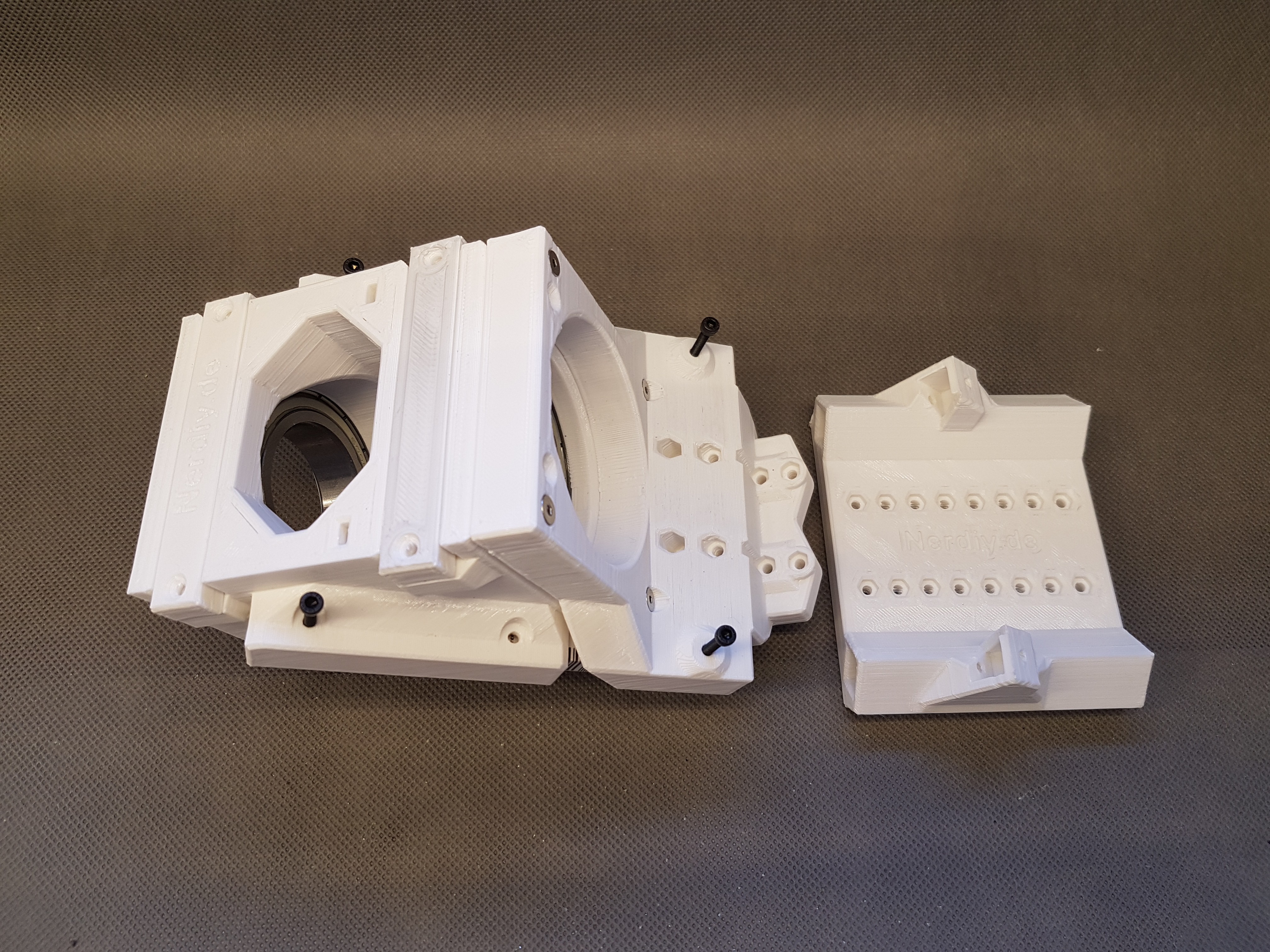
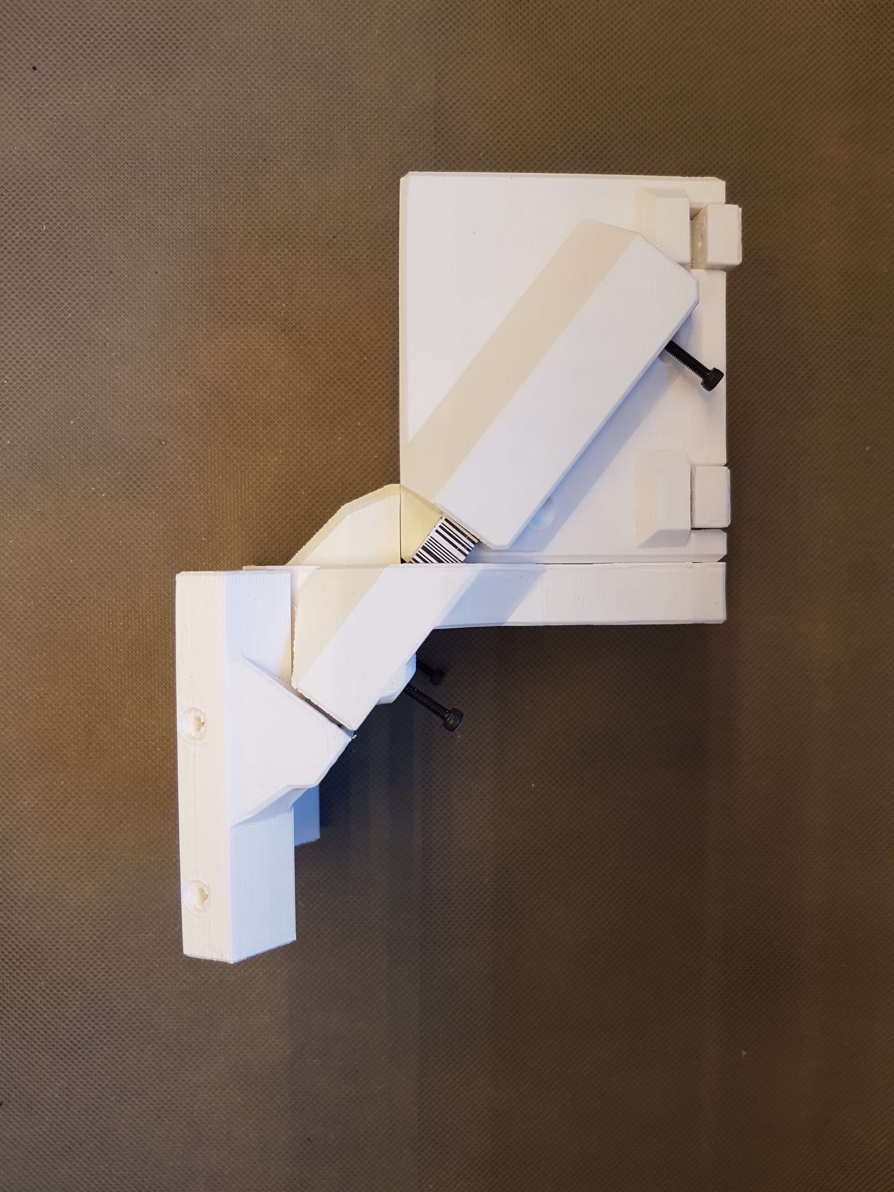
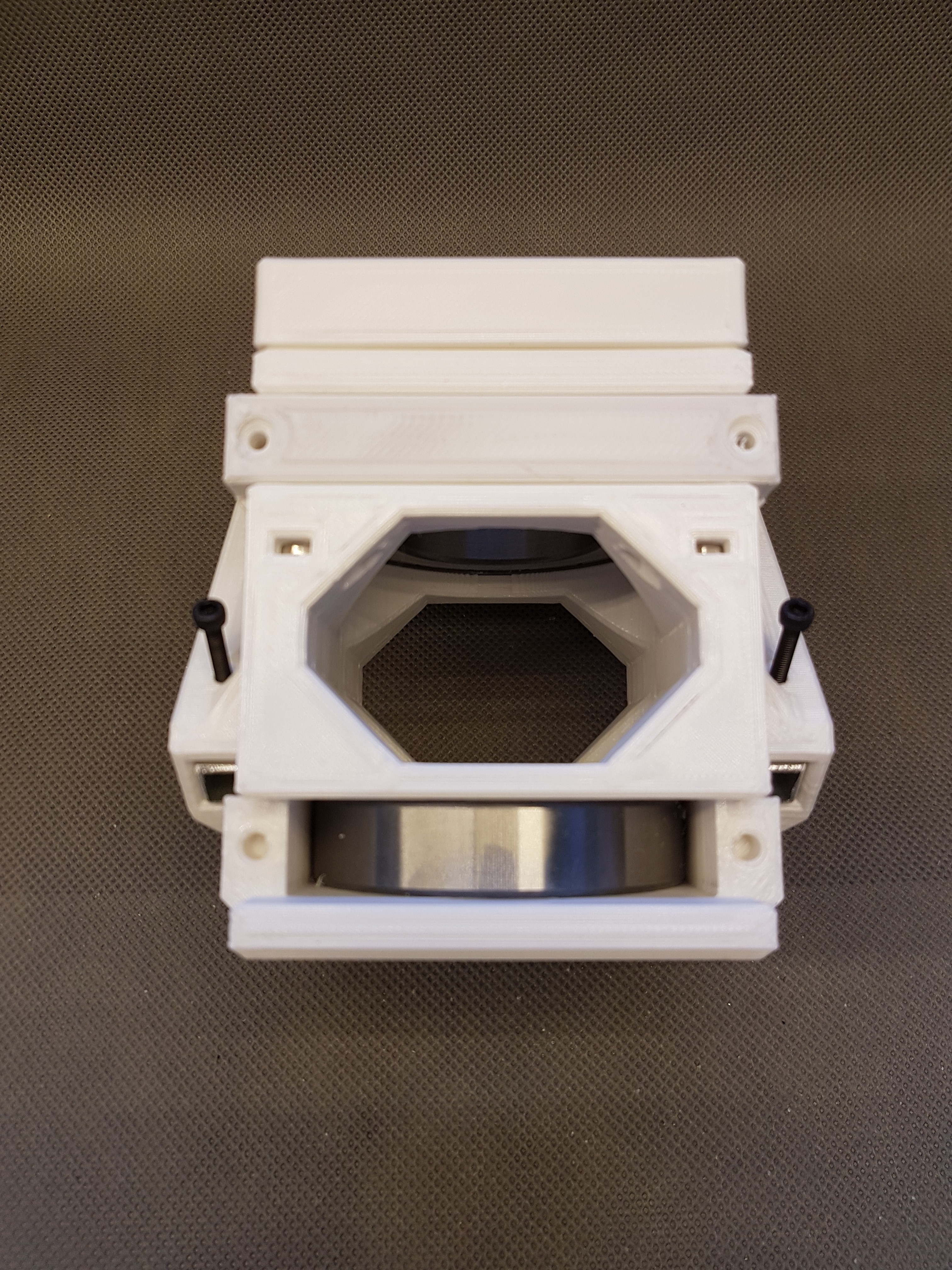
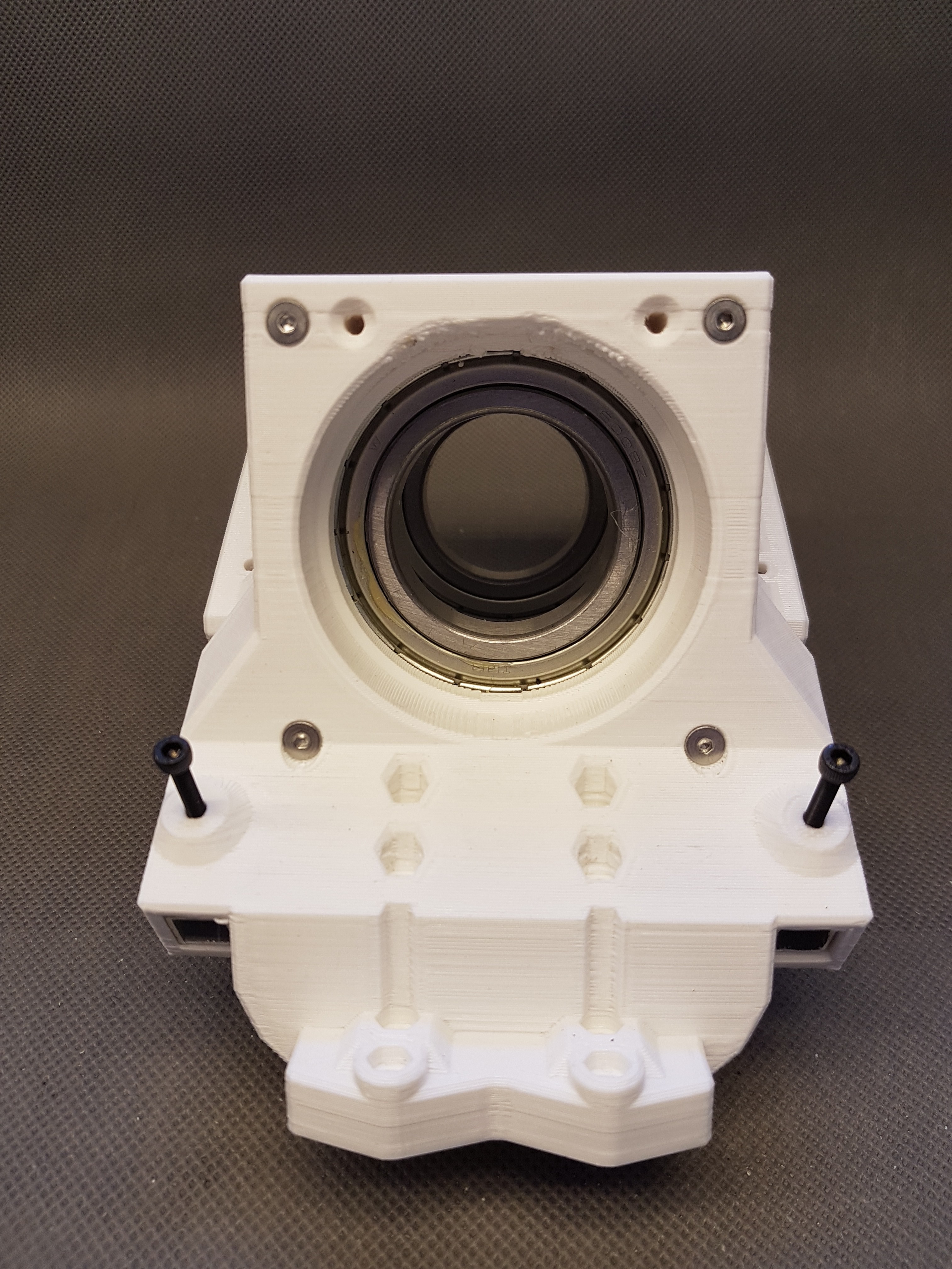
The new design of the main shaft bracket actually consists of two parts. (this is also a relief compared to the six parts in the previous design). In addition to the screws, these two parts are connected to each other by two aluminum profiles on the side of the bracket. In addition, these profiles extend into the holder on the base of WinDIY. There, this can be connected again with a long screw with the aluminum profile in the base.
The pictures below show the mount from different sides. To give you a better orientation here a picture of the mounted main shaft mount in WinDIY: (Note: The improved mount for the alumnium profile in the base of WinDIY is missing on the picture)
![]()
![]()
![]()
![]()
![]()
![]()
![]()
![]()
-
Turret bearing, new main shaft bearing mount and vane
06/19/2020 at 15:06 • 0 commentsHere is just a small update about the actual state of WinDIY
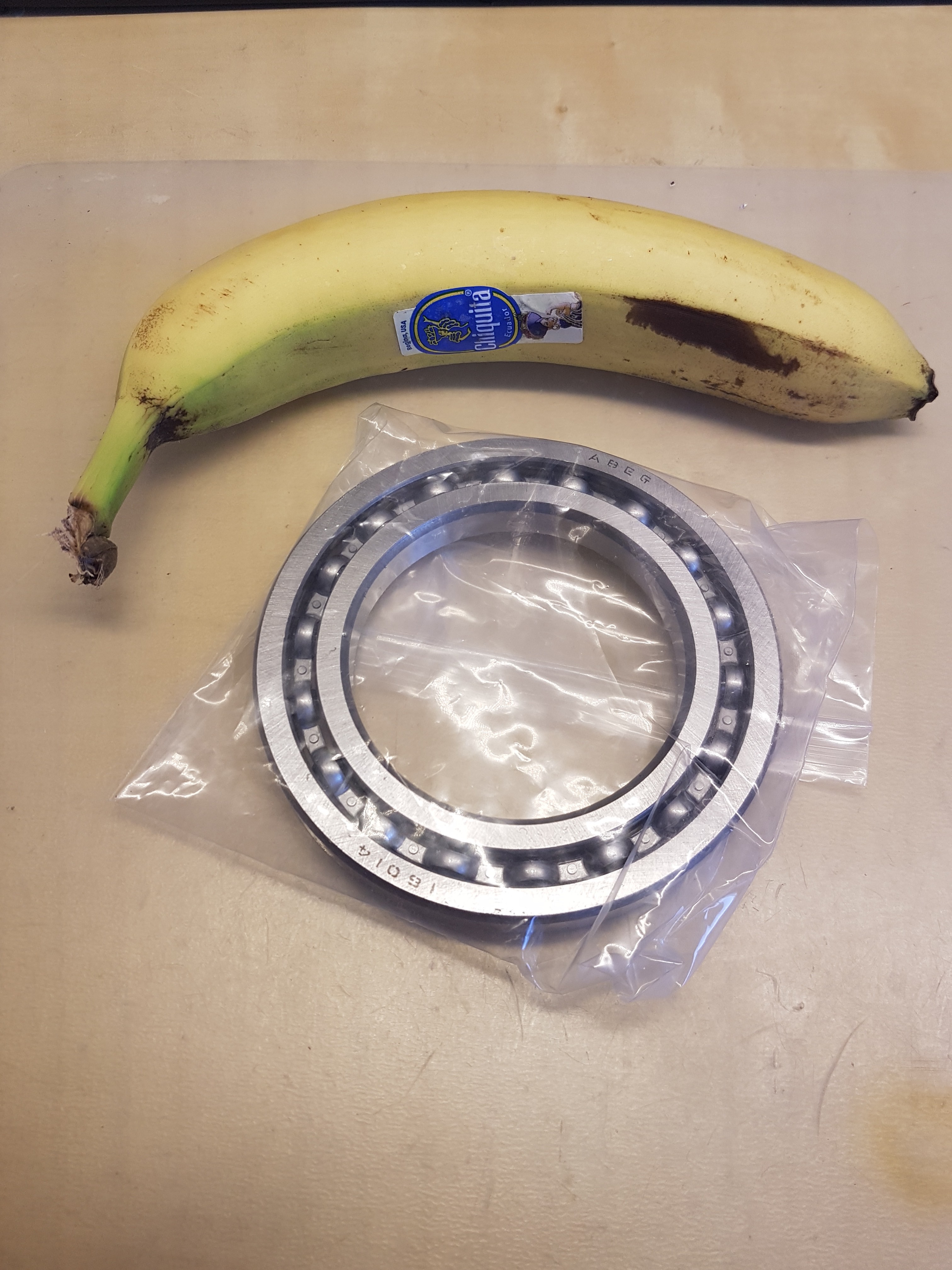
On the pictures you can see the ball bearing that i plan to use for the turret. (Banana for scale) It is actually a radial ball bearing and is therefore only suitable to a limited extent for absorbing axial forces. Since the ball bearing is mercilessly overdimensioned (compared to the low weight of WinDIY), this should work without problems. :)
In addition to that, I have completely revised the mount of the main axis. I will go into this in an extra log entry.
Short story: I think that the old storage would not have lasted long. In the newly designed version, the main axis is held by two radial ball bearings. I call this technique (which is certainly not new) "Aluminum profile reinforced 3D print". :D Please also see the pictures in case of upcomming curiosity. :)
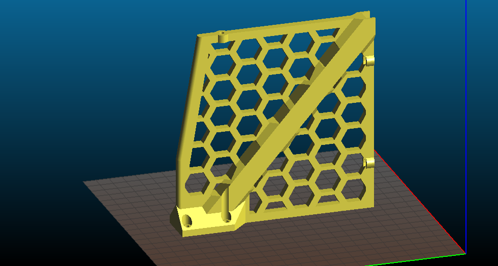
That being said: The past few days I've been thinking more and more about the wind vane for WinDIY. This is the last big and important part of the wind turbine that I haven't worked on yet. A first (rough) sketch of the structure and a photo of the STL file for the first draft can be seen in the photos.
Little cliffhanger: I stopped printing the first draft after half an hour. More on this also in another log entry. :)
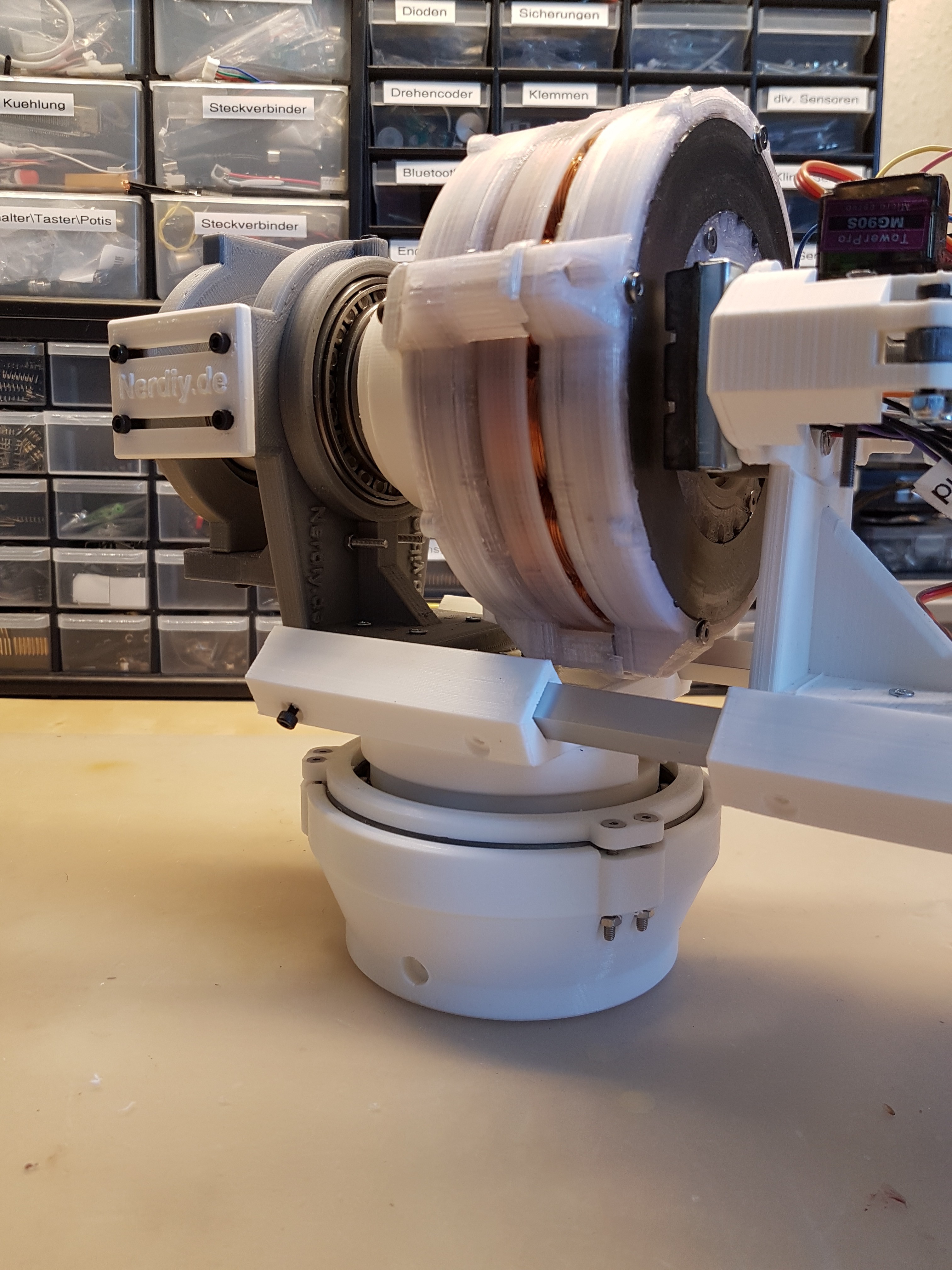
With all of these parts, I largely assembled WinDIY for the first time last weekend. I think now you can slowly see how it should look. :)
Turret bearing:
![]()
![]()
New main shaft design:
![]()
![]()
Rough look including wind vane:
![]()
![]()
-
More words about safety - Electronic load as brake
06/19/2020 at 14:16 • 0 commentsAs you may have noticed, I am also trying to equip WinDIY with a few (in my opinion) important security systems. I planned a mechanical brake and the possibility to adjust the angel of attack on the wings.
In addition, I would always want to keep the generator in a certain load state via an artificial load.
Because what naturally always brakes a wind turbine is the load on the connected generator. You already know this from a small bike generator: as soon as the bike light is switched on, you have to push the pedal harder. What you can also notice (admittedly with a little sensitivity in the legs) is that the resistance of the dynamo increases with higher speed.
The principle is also clear for the wind turbine: the more load connected to it, the more the wind has to exert itself to accelerate the turbine. To a certain extent, when the wind is constant, you can also regulate the speed by regulating the load.
This means that by controlling the energy drawn from the generator, you can also control the braking effect on the wind turbine and thus protect it from excessive speeds. But what to do if the load connected to the wind turbine is not large enough?
If, for example, a connected battery is already fully charged, there is no way to load the generator of the wind turbine. There is simply no way to get rid of the produced energy.
In this case, the load on the generator would decrease, which in turn would reduce the braking effect. If strong winds occur now, this can lead to dangerous speeds of the wind turbine.
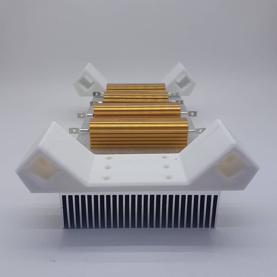
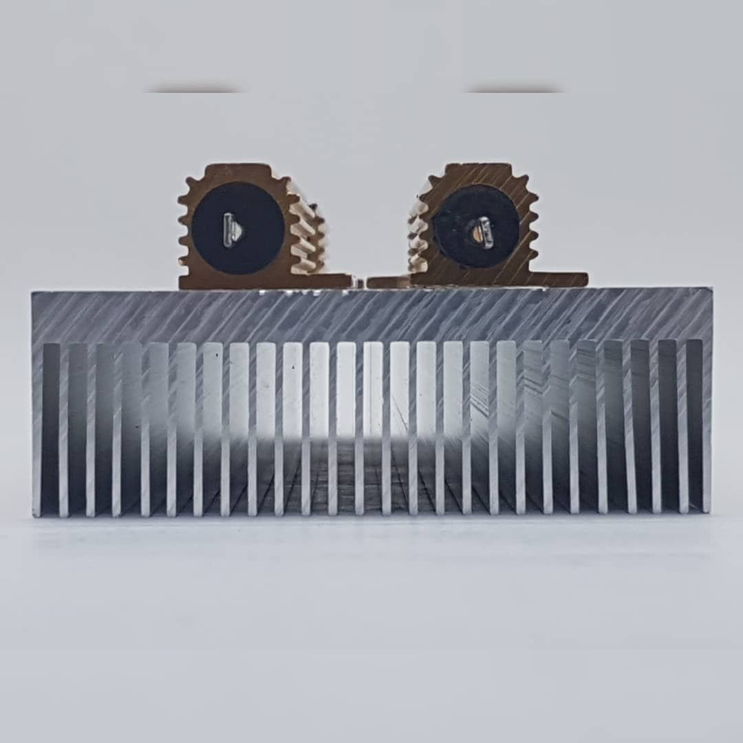
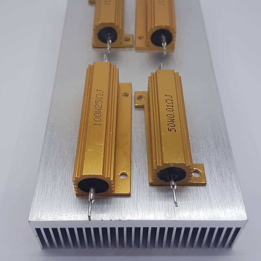
In order to have a "reserve load" available in this case, I planned to mount load resistors on a heat sink and attach them to the boom of the wind turbine. This additional load can easily be switched on if required. The heat generated can then be released into the ambient air via the connected heat sink.
Here a photo of the heat sink and the resistors i received and plan to integrate soon into winDIY.
![]()
![]()
![]()
-
Hub-hood, hooded-hub, hood for the hub... The hub gets a cover :)
06/14/2020 at 12:34 • 0 commentsThe WinDIY hub is literally at the forefront. In addition to the many forces that it has to endure, it also includes mechanics that are quite important for the function of WinDIY.
In addition, most of the mechanical parts come from the 3D printer and (of course depending on the material) are sensitive to weather influences such as UV light.
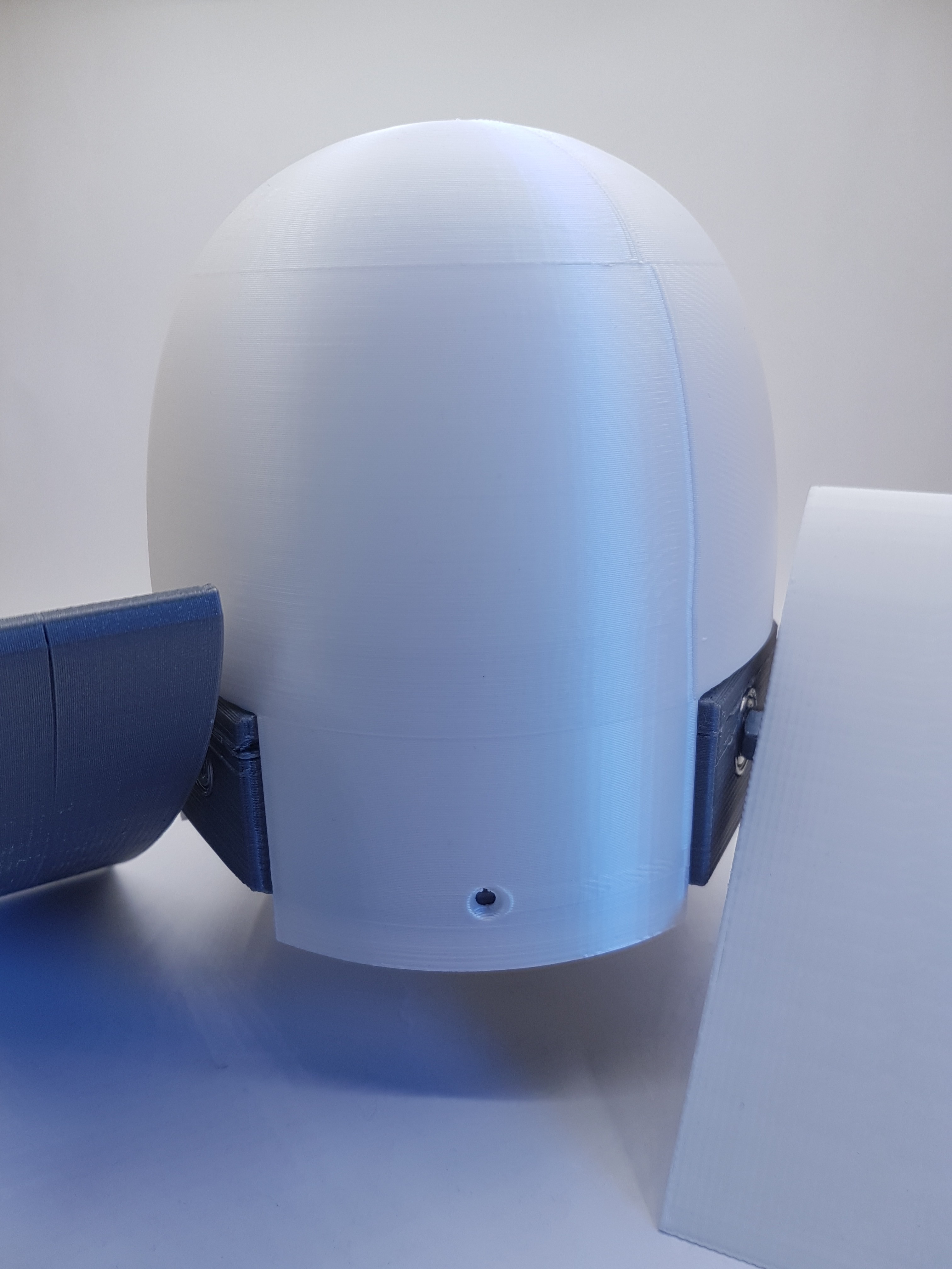
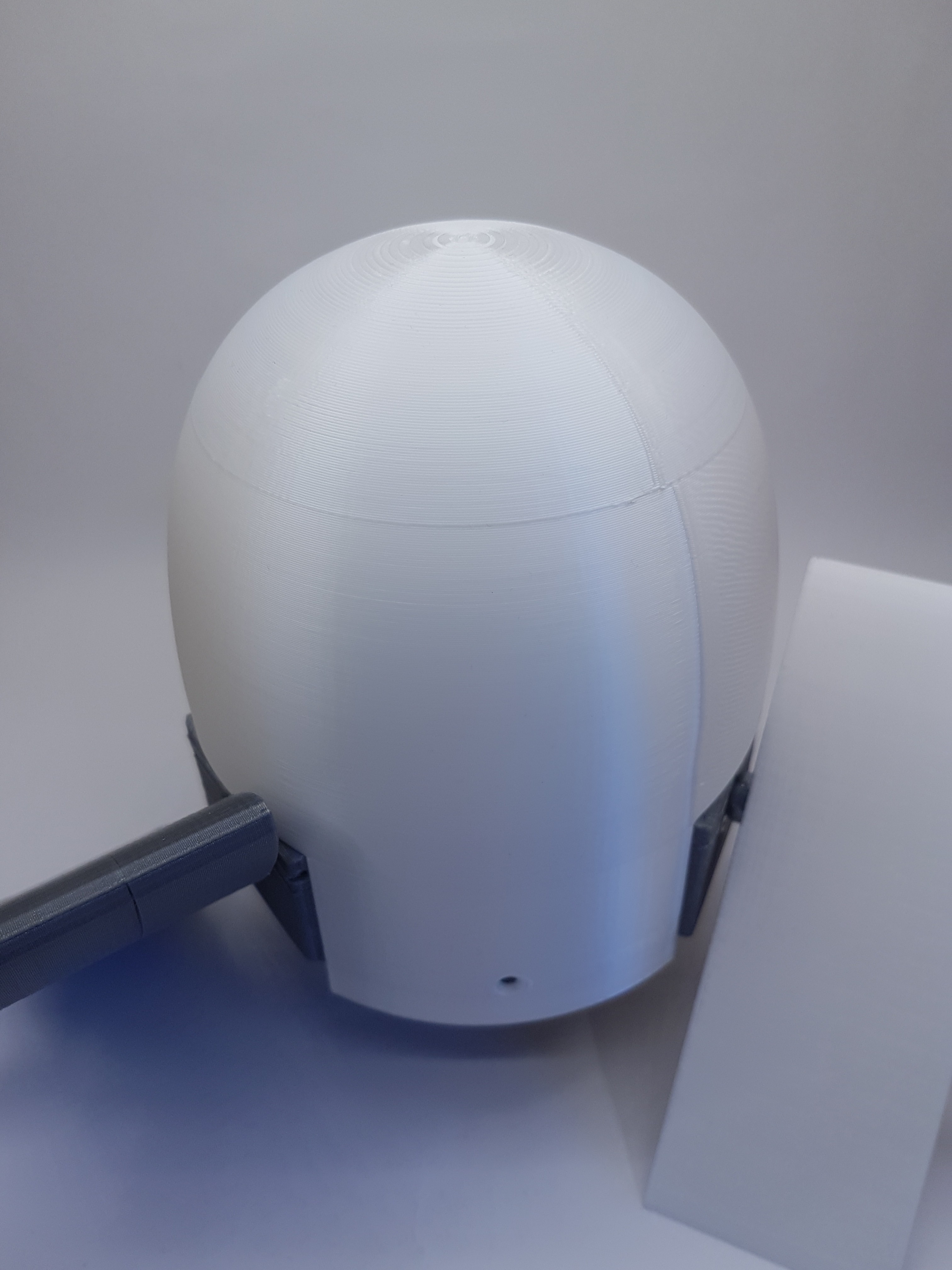
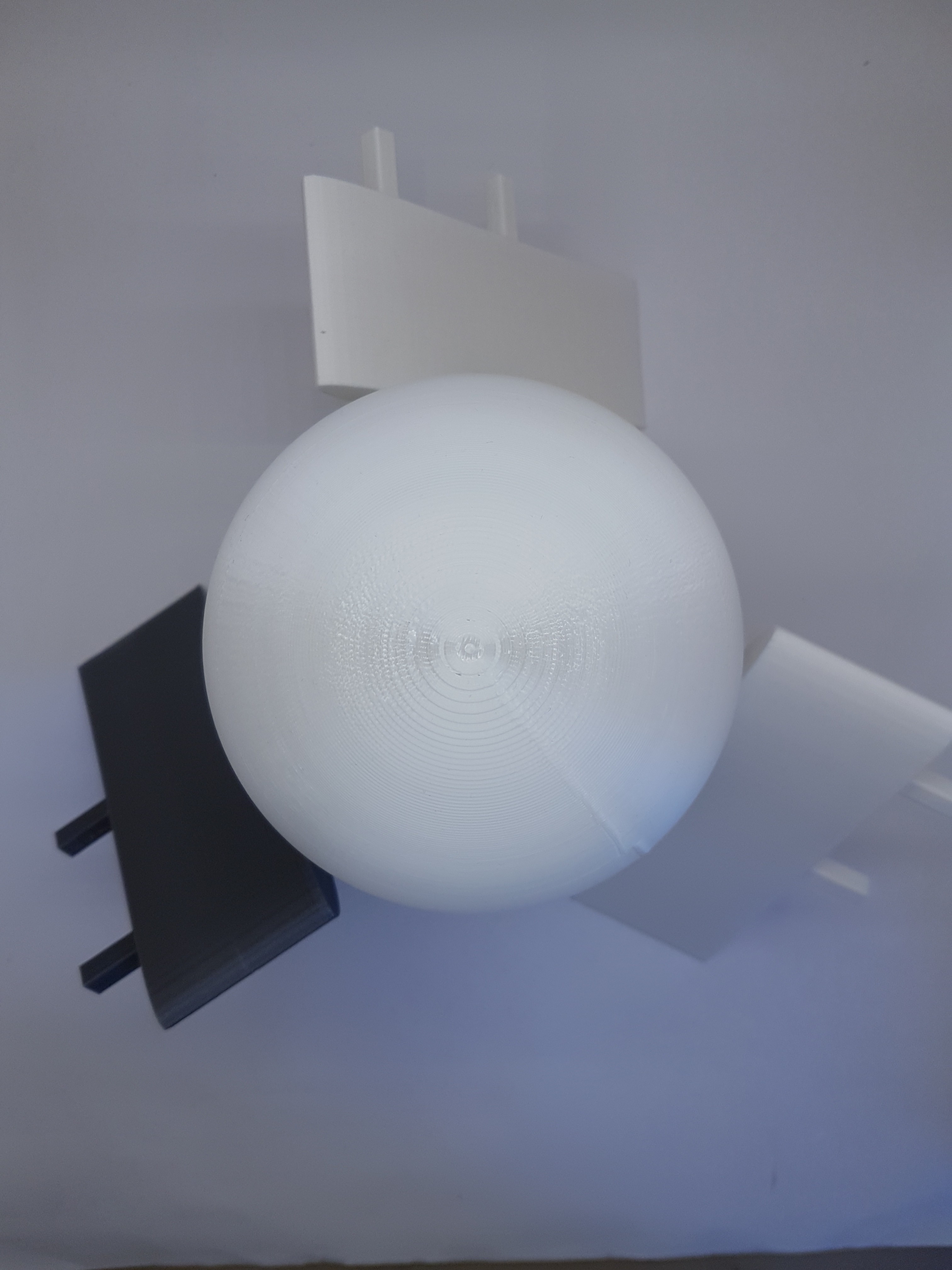
To protect the mechanics and the general structures of WinDIY at least somewhat from the weather, it is of course also provided with a hood. After assembling the hub, this is simply attached from the outside with three screws. :)
![]()
![]()
![]()
-
Some words about safety - The mechanical brake system
06/13/2020 at 11:18 • 0 commentsI think it's always healthy to have enough respect for big rotating things. "Big" starts with relatively small things. For example, nobody would voluntarily want to slow down the kitchen mixer with his bare hand. It is not for nothing that there is an off switch on the kitchen mixer. :)
But what do you do with a wind turbine that turns quickly but should now be stopped for some reason. Turning off the wind (unfortunately and fortunately) does not work.
That's why I tried to think a little about how WinDIY can be reliably controlled or braked even in strong winds. The power (and speed) can be controlled within a certain range using the controlled load on the generator and the pitch adjustment of the blades.
Unfortunately, the wind turbine cannot be brought to a complete standstill. For this reason, I have planned a mechanical brake system.
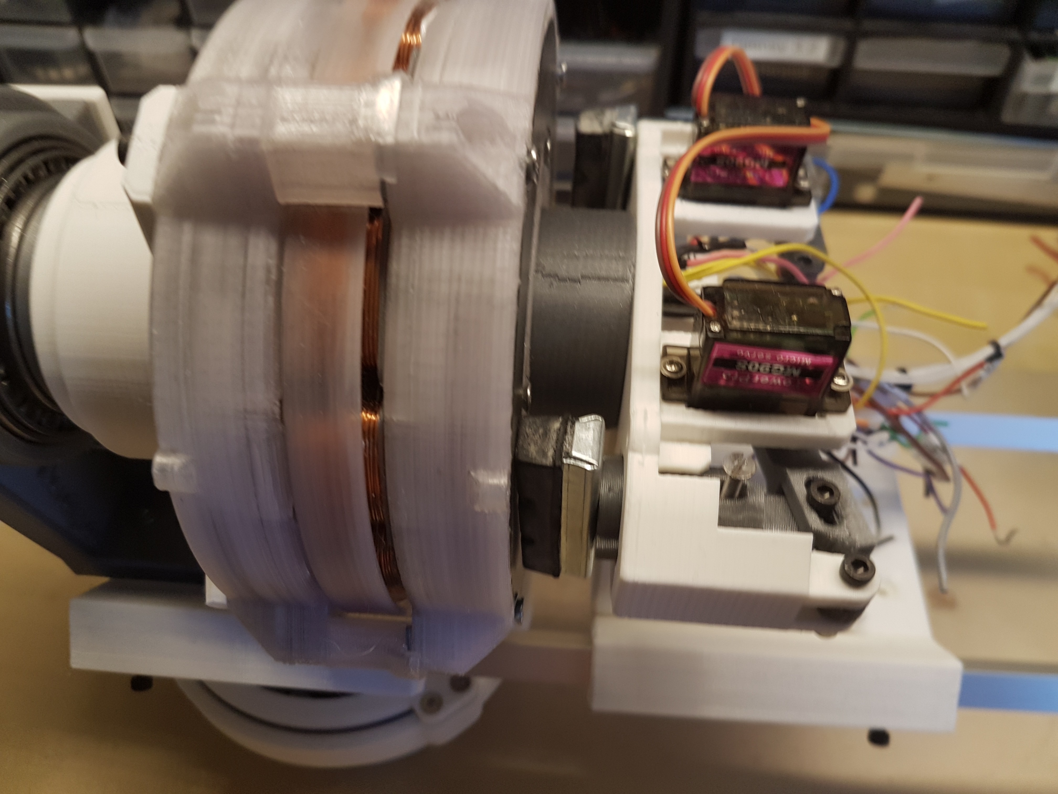
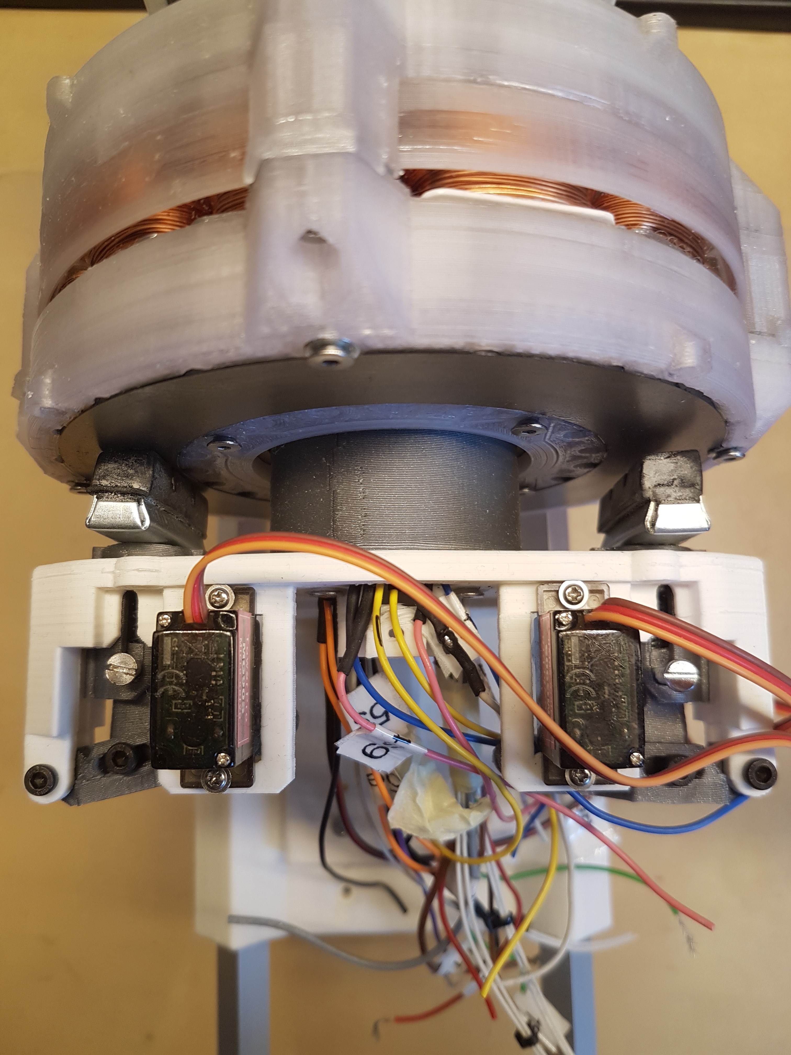
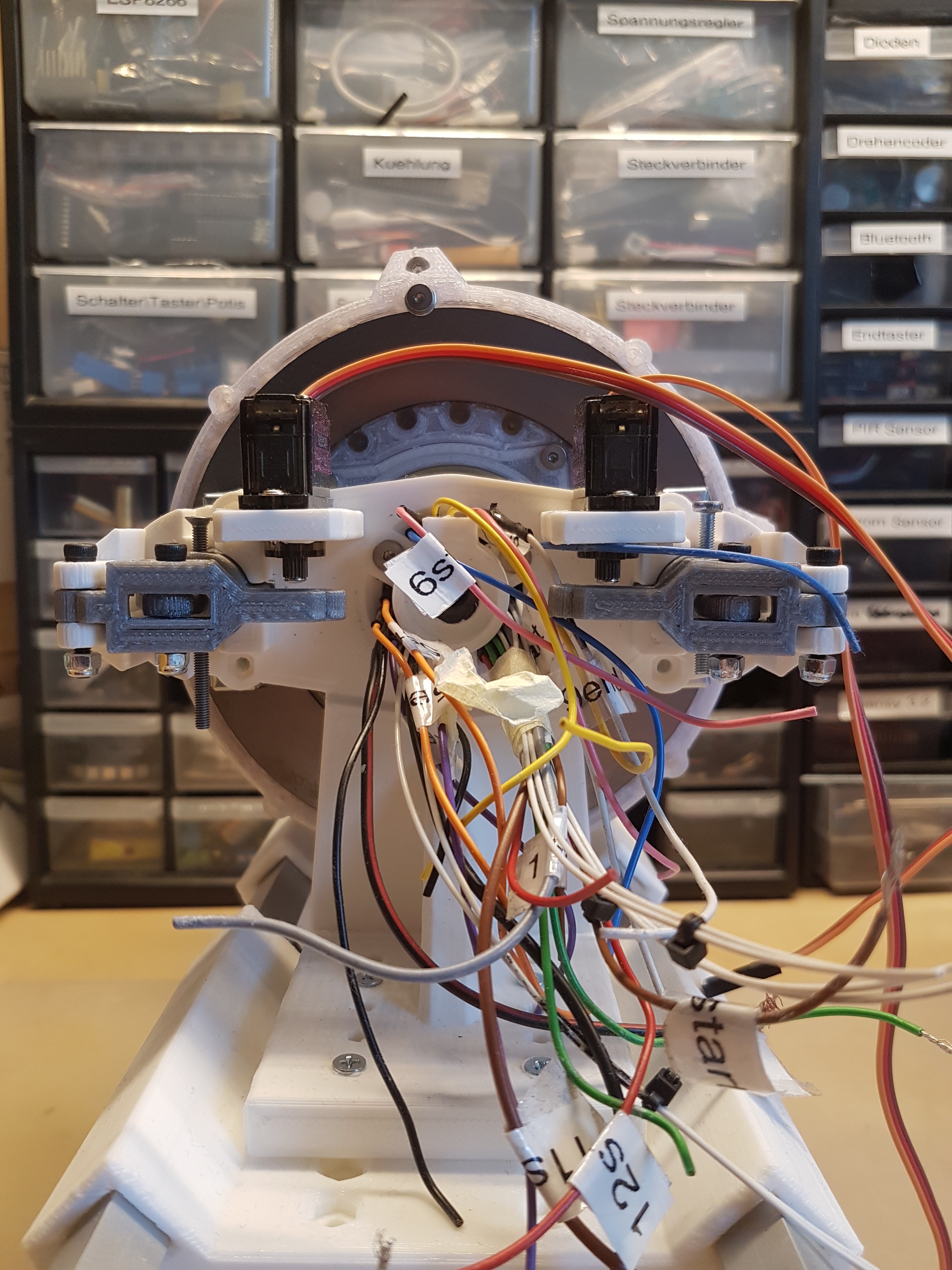
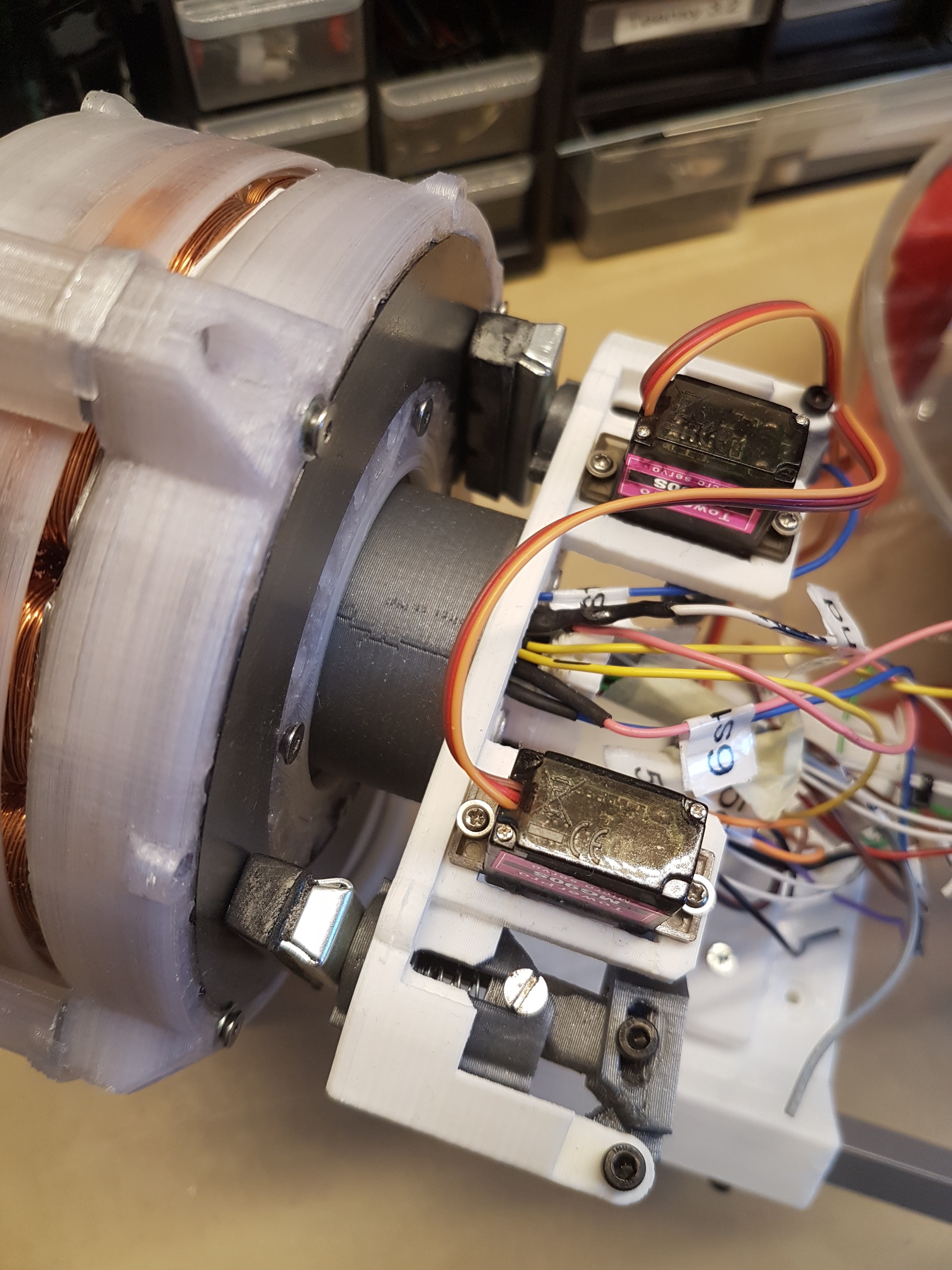
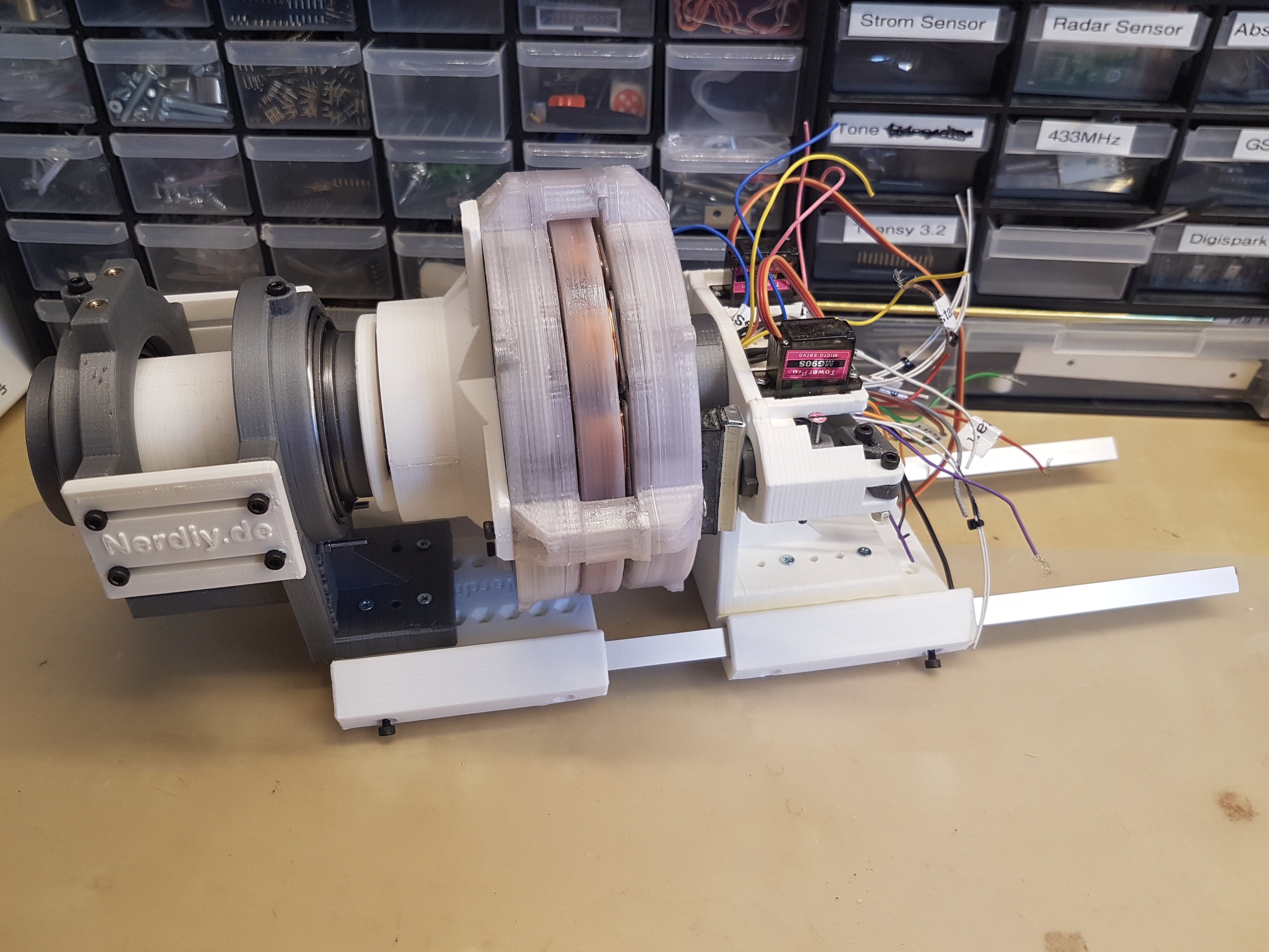
As you can see on the video I used two brake blocks of an old bicycle brake for this purpose. These can (in the current design) be controlled by a servo and pressed onto the short-circuit ring of the disk generator.
This short-circuit ring is actually intended to "short-circuit" the magnetic field lines of the magnets in the disk generator. But it is also very suitable as a relatively abrasion-resistant surface for the mechanical brake. :)
As you can also see in the video, the contact pressure of the (human simulated) servo is by no means sufficient. Here we need more power.
I am currently working on realizing the braking system via a stepper motor. This should drive a spindle, which in turn generates the brake pressure. I also plan to install a sensor that can measure the contact pressure. This way the system could measure which contact pressure is currently present and whether this is already sufficient to reduce the speed. This then spares the stress on the mechanics and the brake pads. :)
So therfore here comes a video and a few photos that basically show how you can NOT design a brake system. :D
![]()
![]()
![]()
![]()
-
The main axis
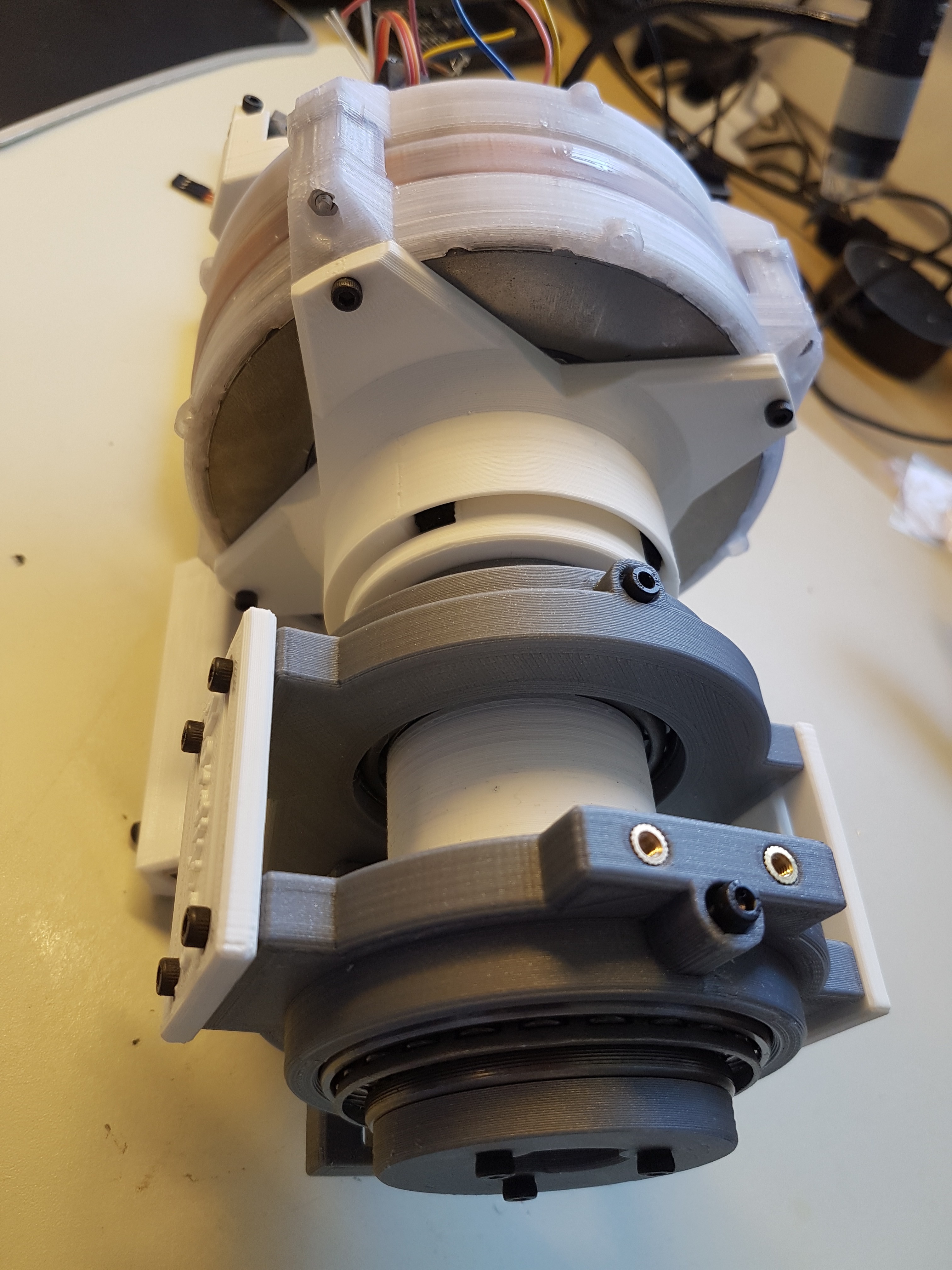
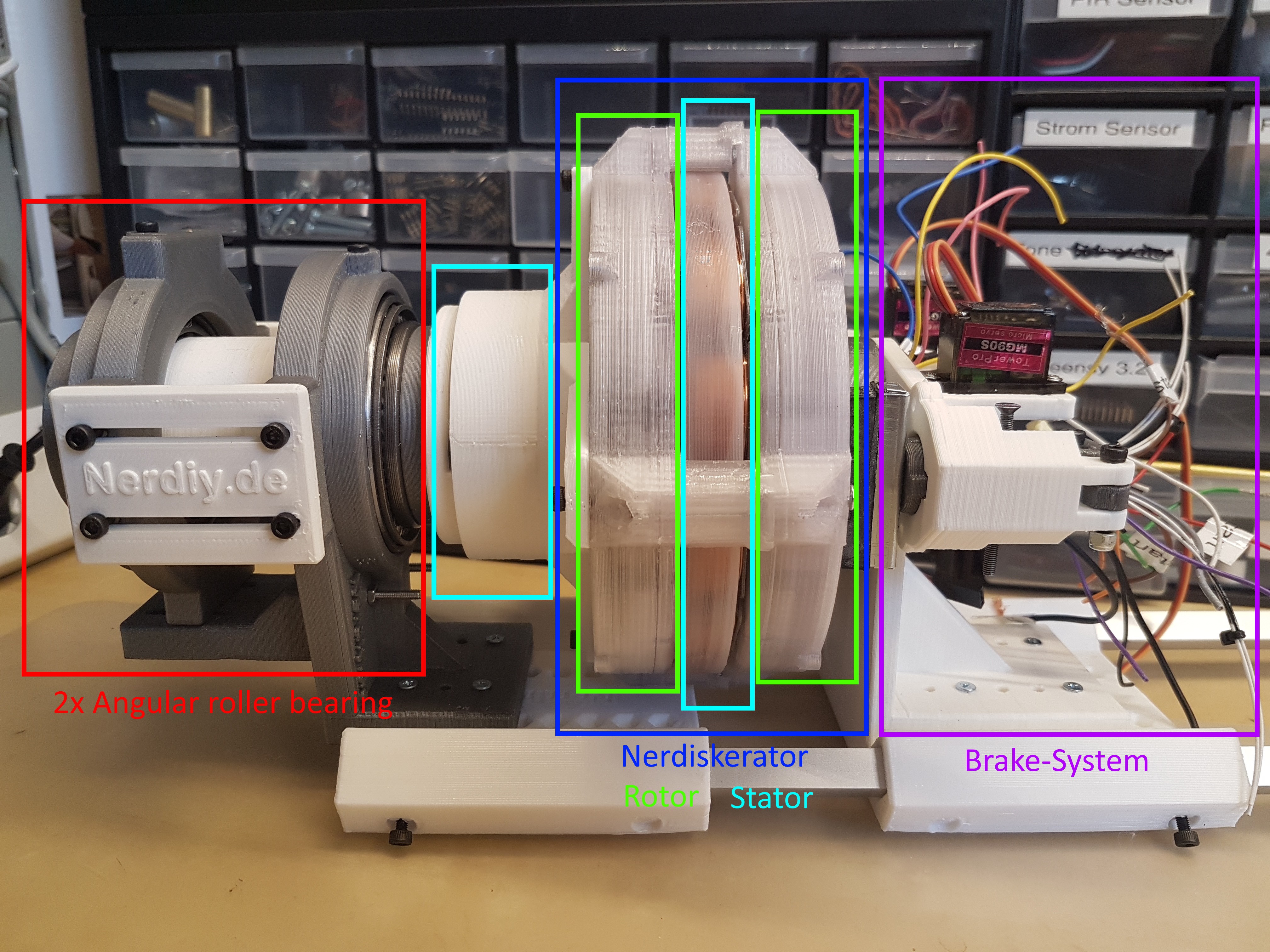
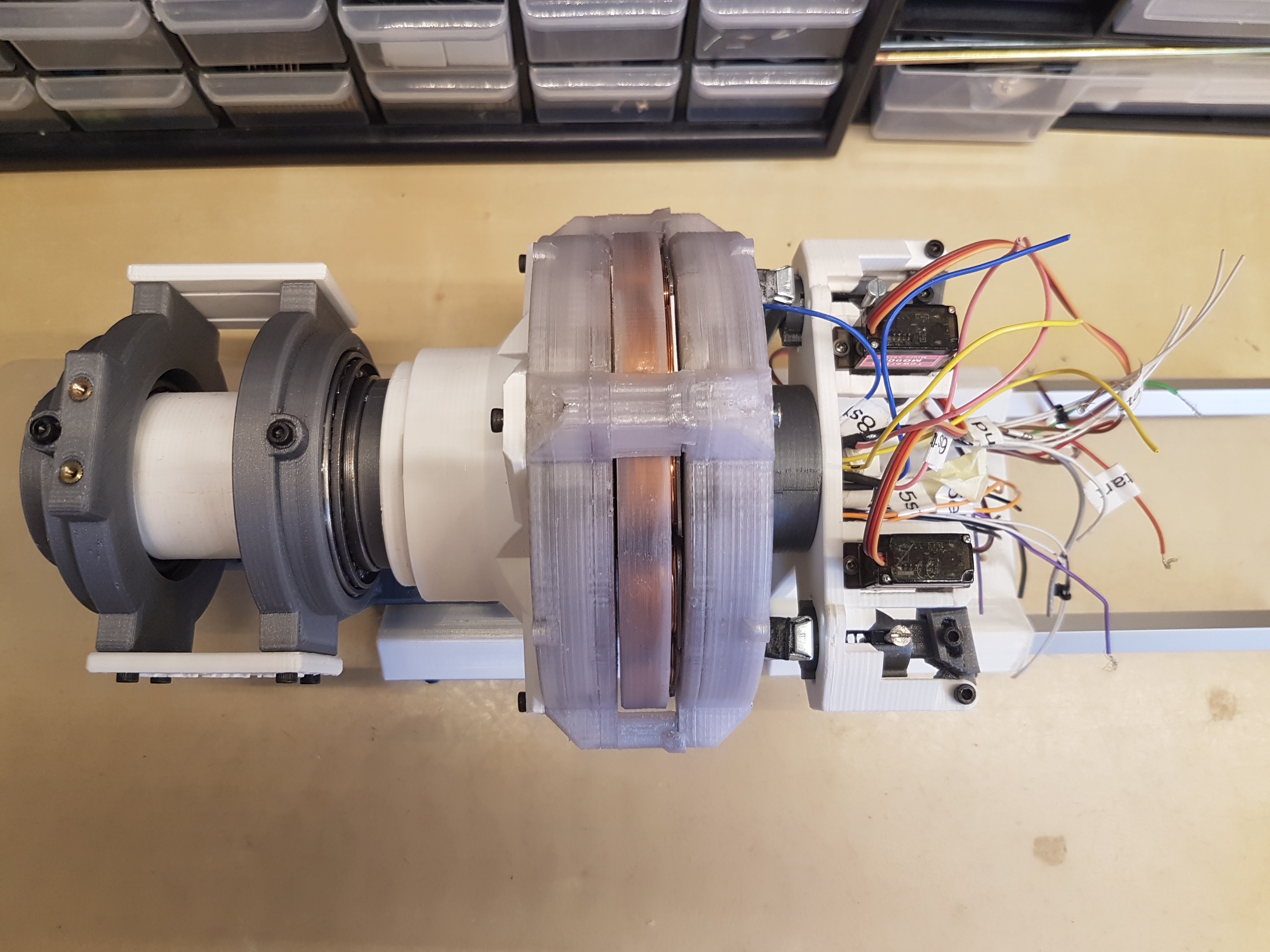
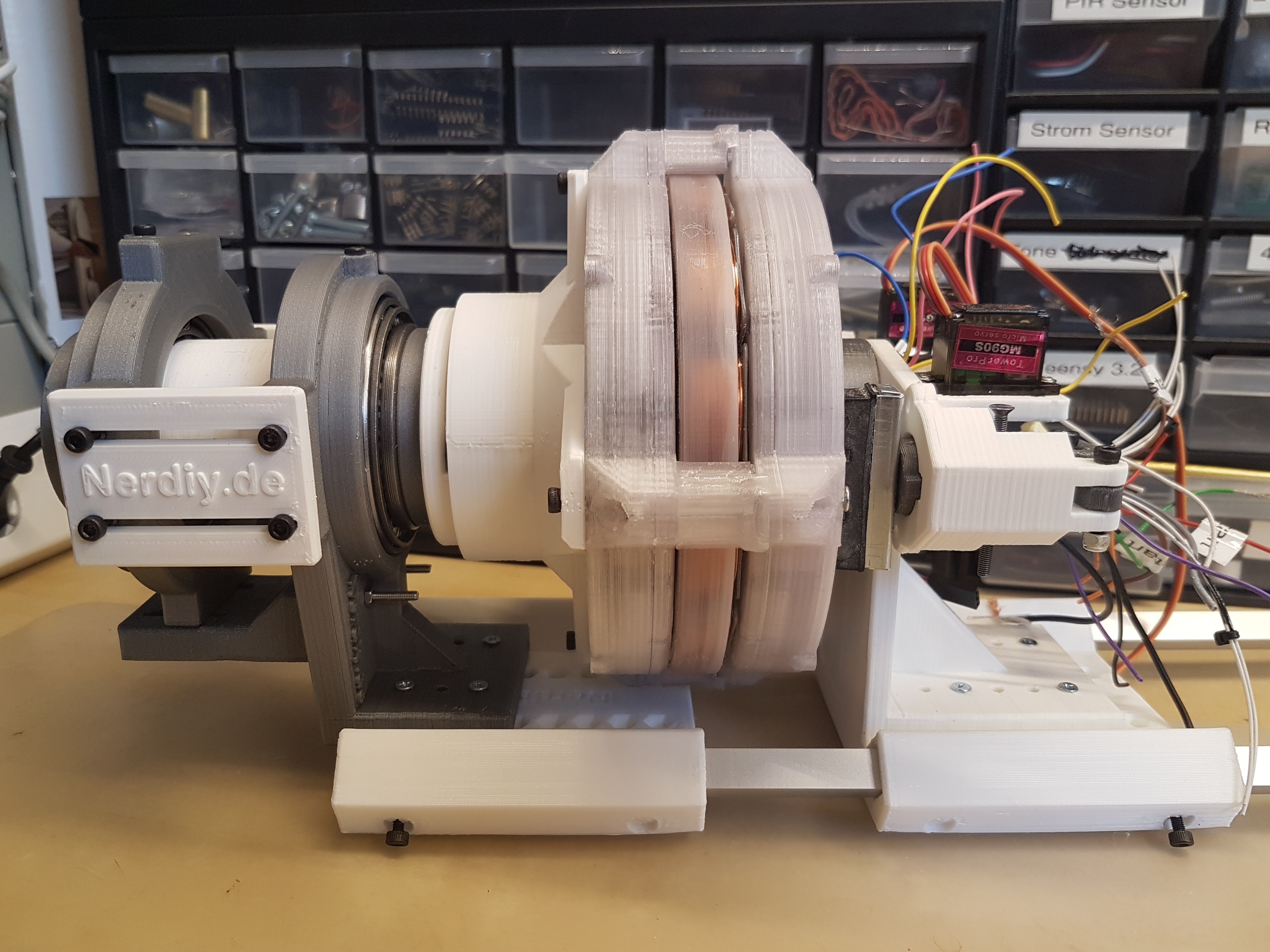
06/12/2020 at 07:36 • 0 commentsI do not know if there is such a thing as the heart of a wind turbine. Ultimately, all parts are important. But the main axis is certainly close to being something like a heart.
Several components are combined in it. Similar to the hub, it has to absorb all forces but at the same time pass on the rotation of the axis to the generator with as little loss as possible. In addition, it must be freely rotatable so that it can be aligned in all directions. Last but not least, it should also include the mechanical braking system with which the wind turbine can be stopped completely.
In the "Nerdiskerator" two ball bearings are installed, which could possibly even take the weight and the forces of the wings. But, I did not want to put additional wight/forces on these ball bearings. After all, they already carry an important payload. :)
That's why I built a shaft in front of the "Nerdiskerator" which is supported with two angular roller bearings. These can accommodate not only the radial (perpendicular to the axis) but also the axial (in the direction of the axis) forces. I had hoped on the one hand to support the shaft in a stable manner and on the other hand to support it smoothly and quietly.
This shaft is connected via a rubber damped coupling, which enables the rotation to be transmitted. (More on that later)
The whole thing is held together using the same aluminum profiles that I had already used when building the wings. These will later also serve as outriggers to mount the wind vane.
As always, here are a few photos of the described structure:
![]()
![]()
![]()
![]()
![]()
-
WinDY Wing Mark 3 - A modular, easy replaceable and scalable blade
06/12/2020 at 07:05 • 0 commentsAs already teased, I was not 100% happy with "Mark2" of the WinDIY Wing. It was heavier than the first design, and there was no possibility to easily replace the wing and, if necessary, to repair it.
Generally, at WinDIY I try to keep all parts as modular as possible. In my opinion, this has the advantage that defective parts can be quickly replaced or repaired.
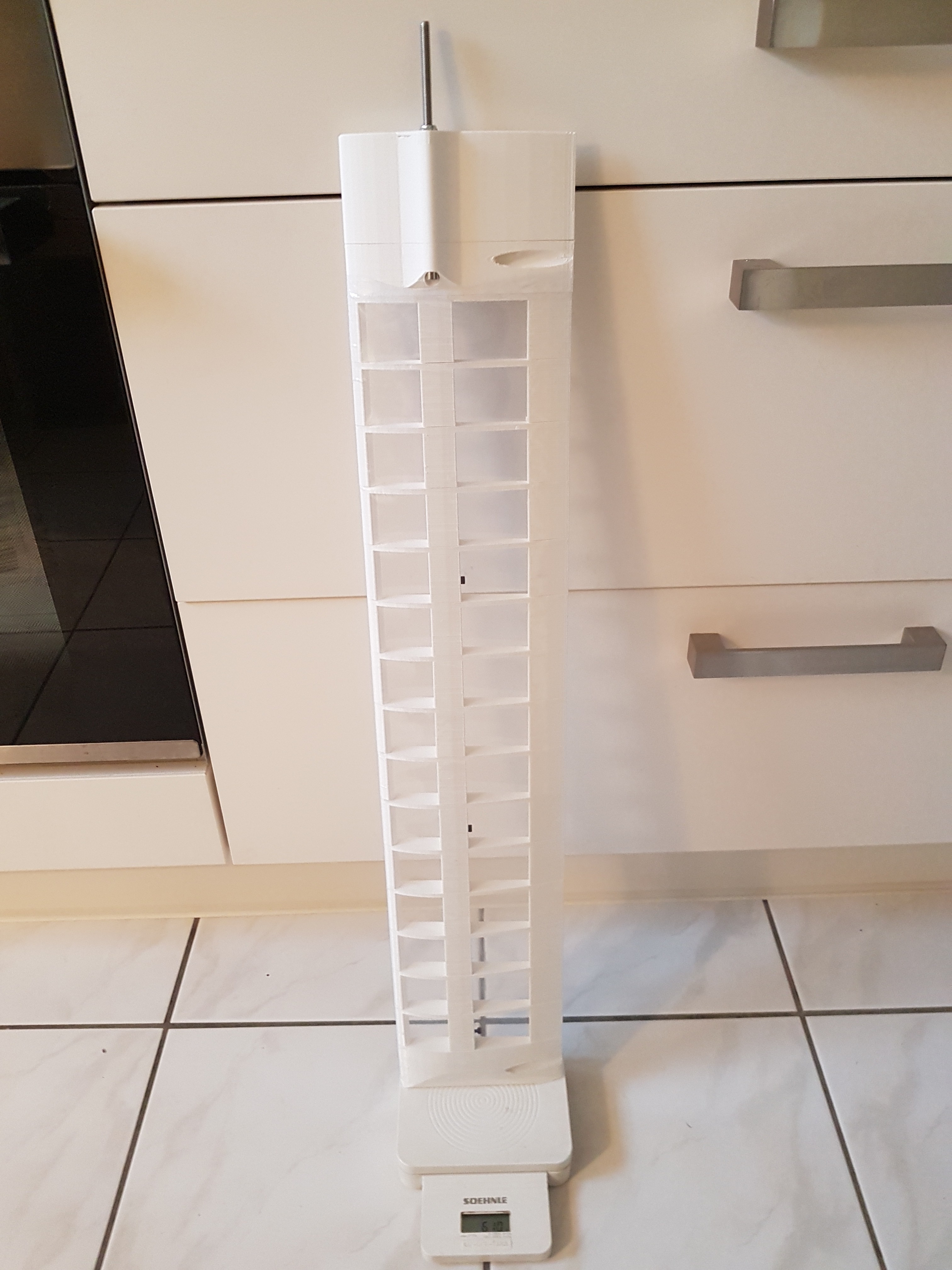
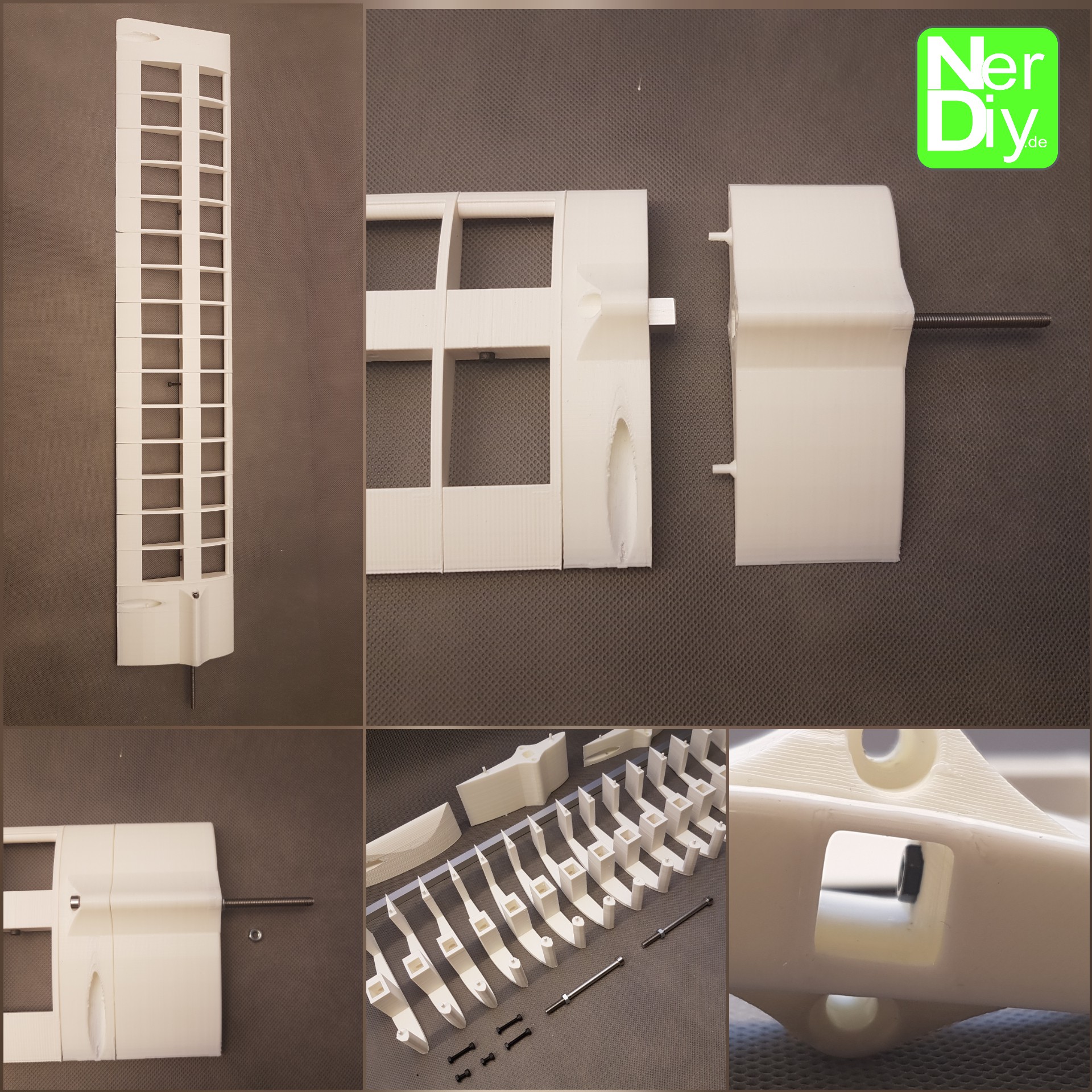
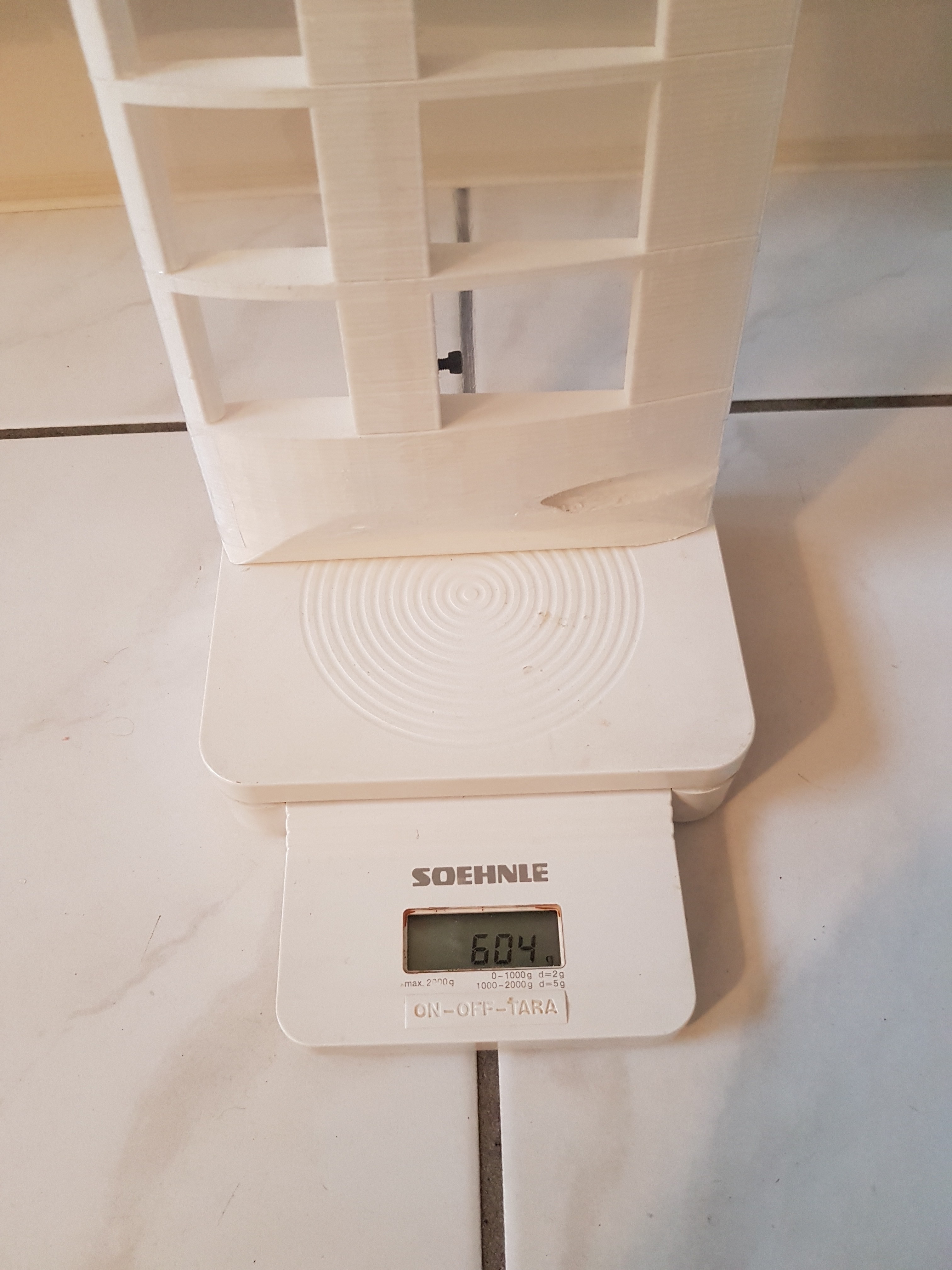
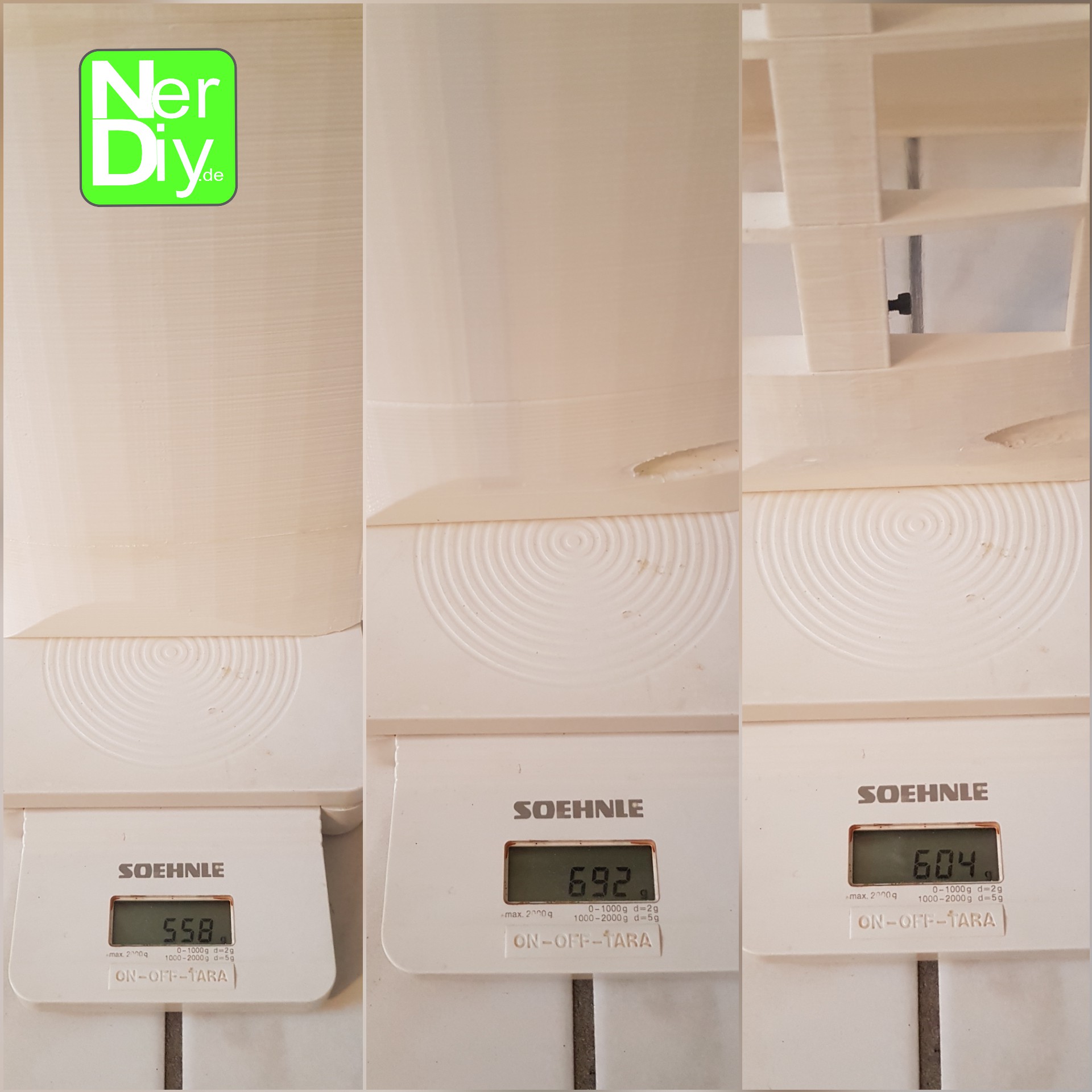
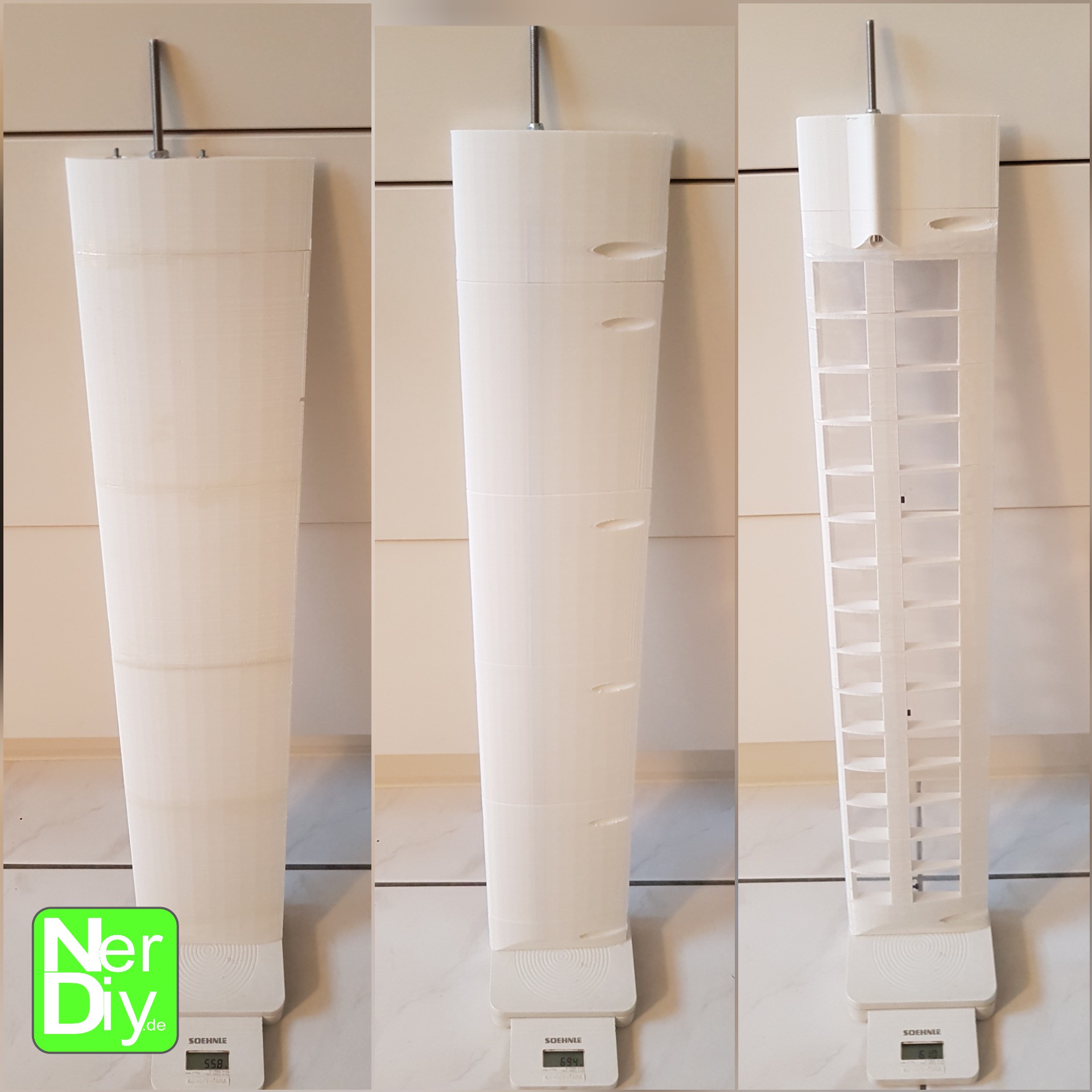
Additionally, parts can be improved step by step without having to completely redesign all other parts.To tackle the problem of weight saving, I checked out a few "tricks" from aircraft wing construction. Just like airplane-wings, "Mark3" is now made up of 15 rafters, which are then covered with a film. So the weight could be reduced to approx. 600 grams which is only 40 grams heavier than "Mark1". Another advantage of this construction is that the number of rafters can also be reduced or increased. So you can make the wing longer or shorter (in a certain range, of course).
In the beginning I tried to stick the rafters individually with very thin adhesive tape. This worked in principle, but it didn't look really durable and, above all, it didn't look good.
At that time, I had given up the further construction a bit frustrated. But at some point I stumbled across shrink tubing on Ebay, which was actually intended to pack battery packs. The diameter of this giant shrink tube also fit over "Mark3". Ordered and tried: The shrink tube was a great solution because it lay flat and tight over the entire wing.
So that no rainwater can run into the wings, I glued the ends of the heat shrink tubing to the 3D printed wing parts. I hope that works. Otherwise I would either have to glue more here or develop another way to get the ends waterproof.
Now I only had the problem that the wing should be easily removable. For this I have divided the base of the wing into two parts, which can be screwed on the front and on the back with an 80mm long M5 screw. So the base part of the wing can remain connected to the hub, while the remaining 60 cm long wing part can be removed. This makes transporting and repairing a wing easier. A load test after the test setup (as shown in the previous log-post) with two 1 kg flour packages also showed that the connection should be able to withstand the load. :)
This is the (so far) last version of the wing for WinDIY. For this I will soon post the assembly instructions here. :)
And here are some pictures including a little comparison of the three different wing versions:
![]()
![]()
![]()
![]()
![]()
WinDIY - HAWT Wind turbine
Mostly 3D printed HAWT windturbine incl. 3D printed disk-generator and brake system.