-
1Preface
The goal of Aruna is to create a platform for ROV development, kinda like what ROS (Robot operating System) is for robots or Ardupilot¹ is for drones. Aruna is however not a framework, it is only meant as C++ library to aid in the software development. You are free to implement it however you want. And how much you wish to integrate it into your project.
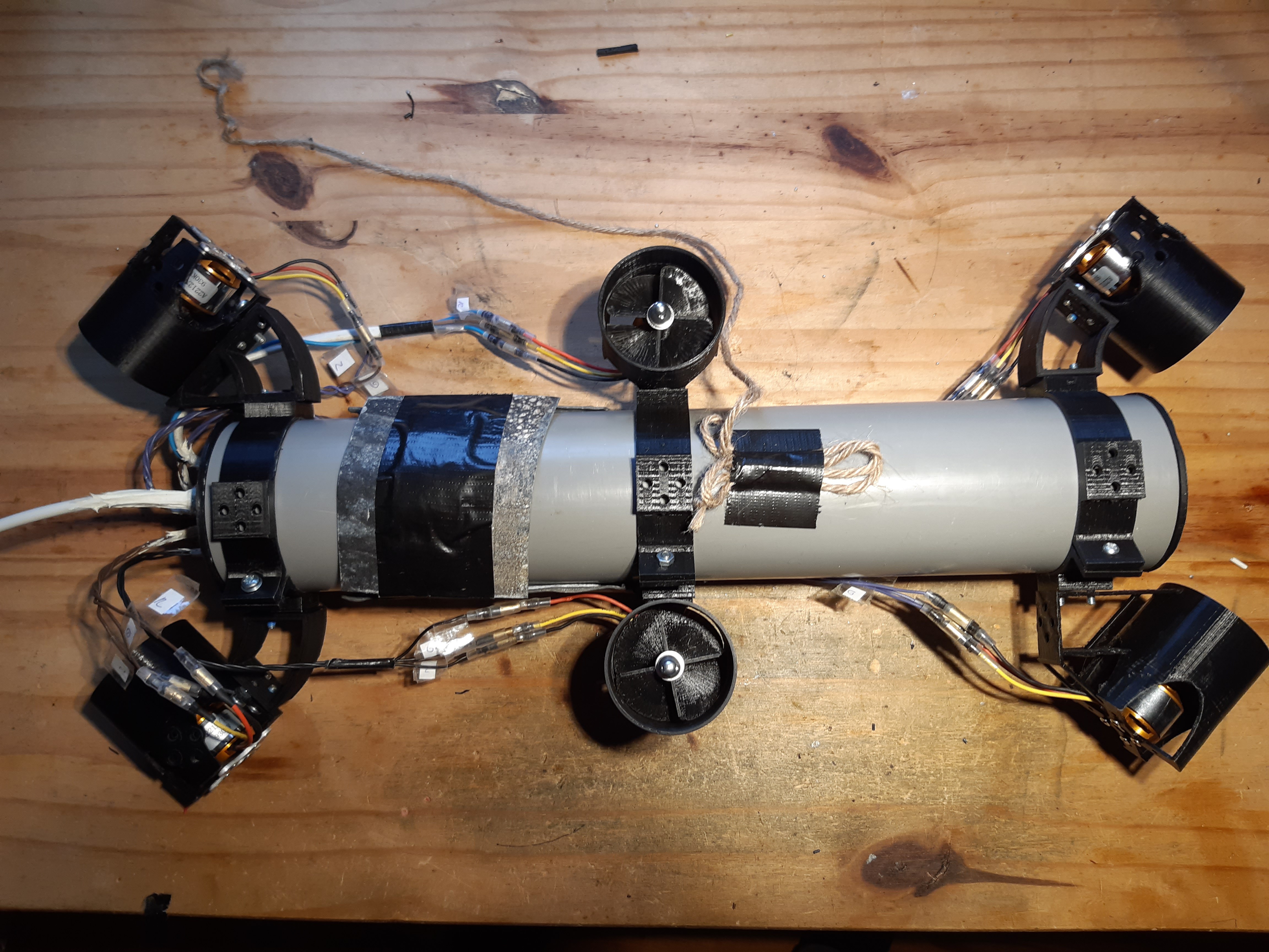
The Aruna project is however not limited to just software. It has also an arsenal of CAD object to be used (or modified) for the mechanical part of the ROV. As it has some electronic PCB design for the implementation of Aruna. All of this can be altered by the user so you can create your own unique ROV (or AUV (Autonomous underwater vehicle) with additional software). It is therefore difficult to create an instruction set as I encourage you to design and create your own. The steps in this instruction will thus assume you want to create an MVP (minimal viable product) Aruna ROV similar to the Apsu implementation (Cylinder ROV powered by ESP32 as seen in picture) that I build. But without the PCB design (as it's expensive and not yet ready). Please deviate and use your own creativity wherever you see fit.
¹ I have no experience with Ardupilot.
-
2Necessary parts
- ESP-32D (S should also work but why bother)
- RS485→ UART breakdown board (for communication from ESP to computer)
- RS485→USB (for communication from computer to ESP)
- 10 meter long cable with 2 wires for RS485 (Ethernet cable works fine)
- 3D printer w/ filament of your favourite colour
- 6xA2212 930kV BLDC motor
- 3x6x 400-100 mm wires (for connecting the BLDC motor to ESC)
- 6x BLHeli ESC
- 80mmx400 mm PVC pipe
- 2+4x rubber ring (for closing up the cap of the PCV pipe)
- 4x6x M4 screws and bolds
- 12V power source for ESC, motors (9x18650 battery cell recommended)
- Battery management unit (optional)
- 3.3V power source for internal logic; ESP (buck converter from 12V power source recommended)
- 5x 10 mm strain relief (for every outbound cable)
- FT2232H like the ESP-PROG for programming (Optionally but highly recommended)
-
3Create development environment
- Install ESP-IDF v3.2.x (v4.x might work as well, not tested though)
- install cmake
- install openocd-esp32
- clone Apsu in your git directory
- `cd my_git_dir`
- git clone https://github.com/aruna-rov/Apsu
--recursive
- don’t forget recursively as it needs to clone the Aruna library as well
- run `git submodule init` if you forgot –recursive (in the Apsu directory)
- build the project
- `cd Apsu`
- `cmake . -B build`
- `cd build`
- `make -j6` (change 6 to the number of physical cpu’s on your PC)
- You should now have three binaries.
- build/Apsu.bin containg the main application
- build/bootloader/bootloader.bin containing the bootloader
- build/parition_table/partition-table.bin contains the partition table of the image
- An IDE with cmake (like Clion) does this process automatically at a press of a button, but since all IDEs are different it is not covered in this instruction.
- Flash project on target
- with the FT2232H connected to the JTAG of the ESP and to the
USB of your computer run: (adjust path accordingly)
- install bootloader `~/./esp/openocd-esp32/bin/openocd -s ~/esp/openocd-esp32/share/openocd/scripts -f interface/ftdi/esp32_devkitj_v1.cfg -f board/esp-wroom-32.cfg -c "halt reset ;program_esp build/bootloader/bootloader.bin 0x1000 verify reset exit`
- install partition table `~/./esp/openocd-esp32/bin/openocd -s ~/esp/openocd-esp32/share/openocd/scripts -f interface/ftdi/esp32_devkitj_v1.cfg -f board/esp-wroom-32.cfg -c "halt reset ;program_esp build/parition_table/partition-table.bin 0x8000 verify reset exit`
- install main application `~/./esp/openocd-esp32/bin/openocd -s ~/esp/openocd-esp32/share/openocd/scripts -f interface/ftdi/esp32_devkitj_v1.cfg -f board/esp-wroom-32.cfg -c "halt reset ;program_esp build/Apsu.bin 0x10000 verify reset exit`
- with the FT2232H connected to the JTAG of the ESP and to the
USB of your computer run: (adjust path accordingly)
-
4build physical object
- print necessary parts: (get them from
https://github.com/aruna-rov/ROV-CAD-objects)
- 6x BLDC
- 4x 45_deg_mount
- 3x universeel_houder
- 1x dop
- Four times: mount BLDC and 45_deg_mount together with the BLDC facing up and the 45_deg_mount making a 45 degree turn, attach the 45_deg_mount to the universeel_houder to create a U shape, for Y and X movement. (tip: see pictures of the alignment in this blog)
- Two times: mount BLDC porpundiclier to the universeel_houder for Z axis movement. (tip: see pictures of the alignment in this blog)
- Wire all the wires through the holes in the dop and glue (or kit) the cables in place using the strain relief and a rubber band so it is water tight.
- Connect the ESP, battery, RS485→UART, power source and BLHeli’s (you may need to adjust some code in `./Apsu/src/main.cpp` to your needs and pinouts)
- Put everything inside the PVC pipe, connect all the wires and turn the device on
![]()
Your ROV should have a simulair layout - print necessary parts: (get them from
https://github.com/aruna-rov/ROV-CAD-objects)
-
5Controlling
- To control the ROV we need to install control software on our computer. Currently, only Linux is supported by Inar.
- Clone Inar to your computer
- `cd my_git_dir`
- git clone https://github.com/aruna-rov/Inar
--recursive
- don’t forget recursively as it needs to clone the Aruna library as well
- run `git submodule init` if you forgot –recursive (in the Inar directory)
- build project
- `cd Inar`
- `cmake . -B build`
- `cd build`
- `make -j6` change 6 to the number of physical processors
- run Inar
- with the ROV turned on and the RS485 link between your computer and the ROV run inar and specify serial port `./inar /dev/ttyUSB0` (modify accordingly)
- Pressing W, A, S, D, Q and E for Y and X axis movement. R and F for Z axis.
- decrease/Increase speed with “[” and “]”.
-
6Have fun!
Enjoy your ROV, if any questions were unclear you can always contact me.
 Noeël Moeskops
Discussions
Become a Hackaday.io Member
Create an account to leave a comment. Already have an account? Log In.