Noeël Moeskops
-
New Thruster layout, BLDC driver rabbit hole and Embedded Linux
04/13/2021 at 19:02 • 0 commentsNew thruster layout design
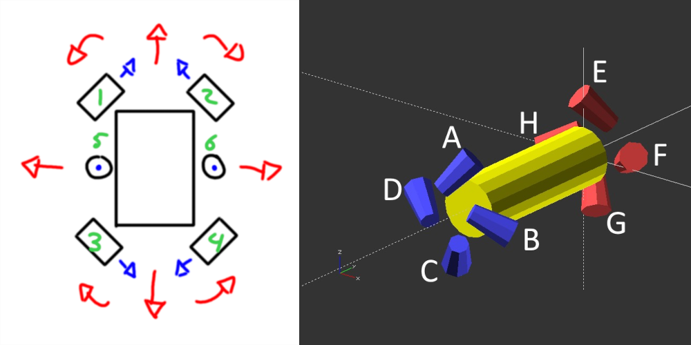
The current thruster design of the ROV is quite agile with the 6 motors the submersible is able to move in 5 dimensions. With the front (1 and 2) en back (3 and 4) motors being able to use to go in 3 dimensions (X axis, Y axis and yaw). While the middle motors (5 and 6) can only make to ROV move in two dimensions (Z axis and roll). Still one dimension is lacking. With the current layout the ROV is unable to move in the pitch axis. This is not necessarily a huge problem as it is not required to move around but still would be nice to move in that axis.

Old 6 motor design on the left. On the right new screw design with 8 motors By adding two additional thrusters, and chancing to total layout the ROV can now move in all 6 dimensions. And it can do so with all 8 motors! Because all thrusters are located at a double 45-degree angle they are effective in all dimensions. They either need to move backwards of forwards. Four motors (A-D) are located at one end of the tube in a screw motion while at the other end the motors (E-H) are rotated in the opposite direction. This prevents the ROV from spinning around its own axis when all motors are active. The only downside to this design however is the cost in part and the power requirements. But regardless I think it is a worth it to build and try it out.
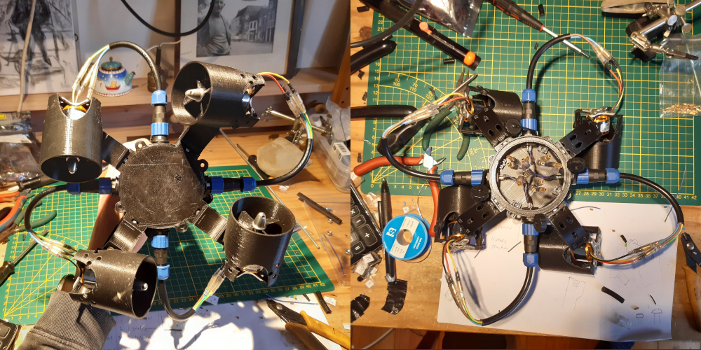
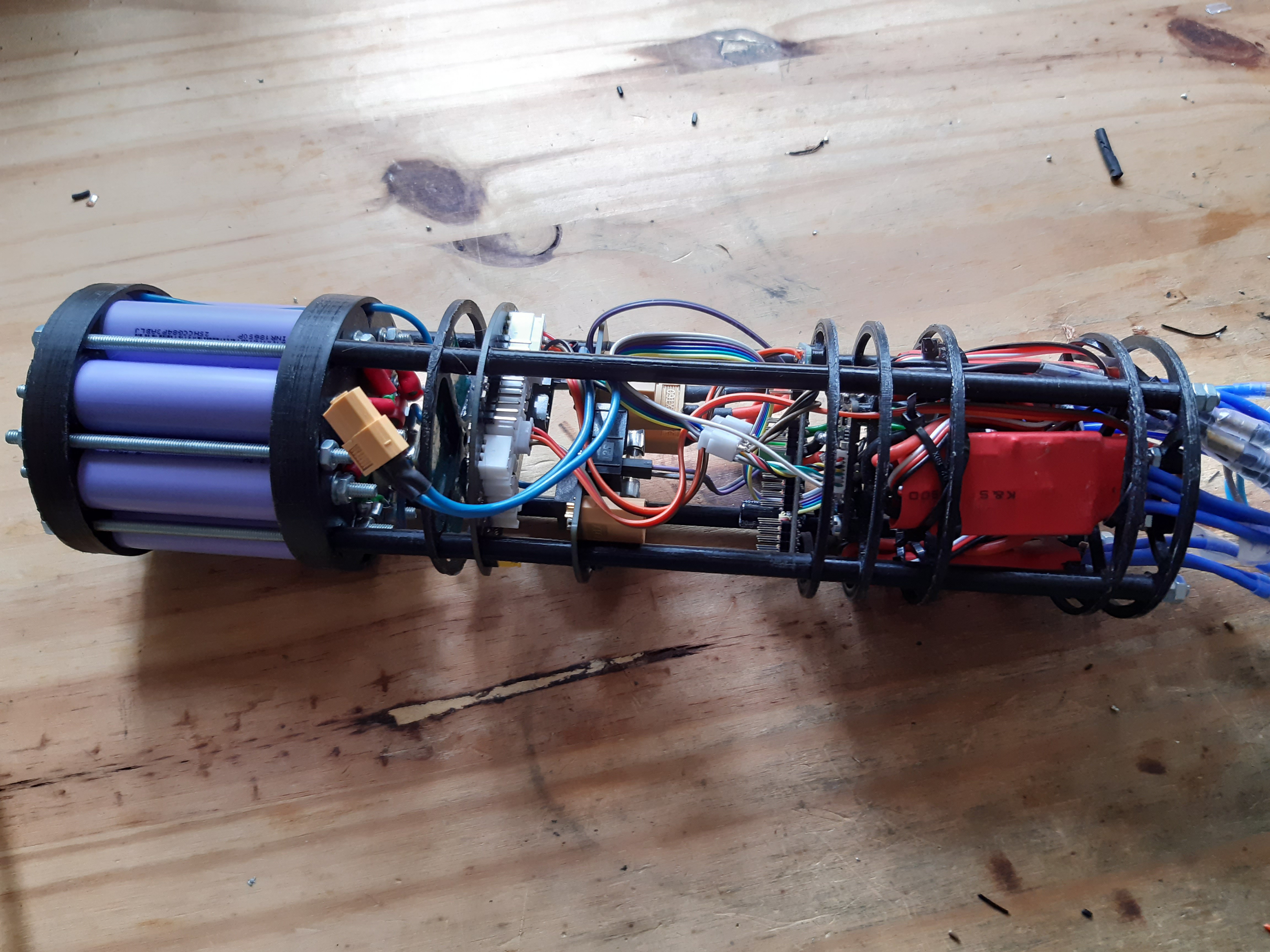
New thruster layout attached to the new cap top and bottom view As can be seen from the pictures I constructed half of the new design. The motors are now intergraded into the end cap with SP13 connectors. But more on that in the next section.
New thruster layout attached to the new cap with the rest of the internals connected also Cap
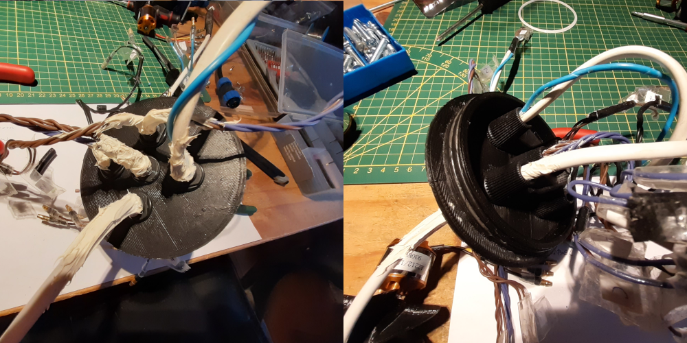
Another thing that really annoyed me was the cap of the ROV. The wires going inward where kitted to a strain relief and the solution was not very nice. The cap contacts the PVC pipe on side via two O-rings. This was not really a nice seal because there was no active force pushing the two together. It could in theory come loose mid-dive (what I was always really afraid of).
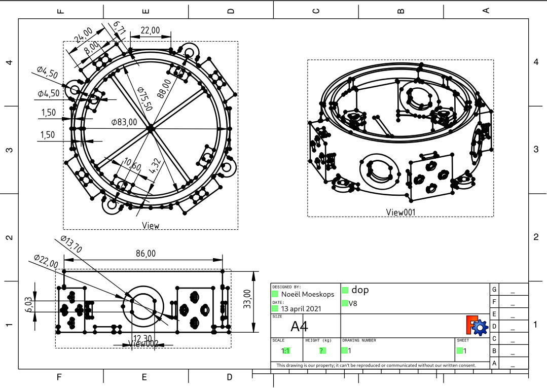
Old cap design, note the two O-rings and the wires kitted to make a water tight seal The new cap is designed to be forcefully pushed to the PVC pipe by four m4 threads that are connected to the cap at the other side. Between the cap and the PVC pipe is a rubber O-ring to make a tight seal. The cap also houses support for IP68 SP13 connectors which replaces the hacked kitted strain relief. And are much nicer all together because they can be reattached easily. The new cap is also integrated into the internals of the ROV. Where before they were two separate parts. Now the cap can be screwed into the other internal component by four m4 threads also.
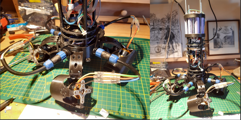
New cap design with holes for SP13 connectors and intergraded connection for the thruster BLDC motor controller
Apsu is currently driven by four SimonK motor controllers and four BLHeli controllers. The SimonK drive the motors in the front and back while the BLHeli provide control to the motors for upward and downwards motion. The SimonK controllers were chosen because at the time I did not know the existence of BLHeli. Now when I have had some experience with BLHeli I'm not liking that either. There is very little documentation available and the firmware (properly with good reasons) is written in assembly, so really hard to read. When I implemented Dshot in my project I remembered it being a big puzzle of figuring out how to protocol actually worked. And I had to put together multiple blog posts from various websites before I got a clear image of how to protocol worked and how to interface with it.
Now that I need more motors and thus more motor controllers I don’t really want to go back to BLHeli, not just because of the lag of documentation but also because the pins on my microcontroller are all in use and I don’t have room for a separate pin for each motor if I’m running eight simultaneously. I would also really like to get data like RPM of the motor which is possible with BLHeli but will cost an extra pin for each motor (or you can put multiple together on one input/play with mutexes etc. but that only makes your life harder). I would just really like to control my BLDC motors with an existing digital protocol like I²C, SPI or RS-485 or something similar. After a fair bit of searching it turns out that these “dream” IC exists in various forms. Among others TI and ST have some interesting IC that can be interfaced by either I²C or SPI and just need 6 external MOSFETS to function. I only need to design a PCB. I can then however design to my taste. So it can fit inside the 80 mm tube and have MT30 connectors for the BLDC motors instead of solder points like most motor drivers have.
From microcontroller to embedded Linux
In my last blog I talked about the strain on doing only one continuous thing and keeping too much to my original planning. And that I was going to take a little break from computer science and focus more on the mechanical and electrical aspects of the project. Well, if you have read the previous sections you can see the result of that work :). But lately when I started programming the ESP32 again I noticed that I really just don’t like the platform as a whole. Debugging and programming the chip can take several attempt with me getting frustrated and rebooting the chip en replugging it in a different USB port in the hopes that it will work next time. It really becomes just a strain to program the ESP, it's not fun anymore. I spend most of my “programming” time trying to interface with the ESP32 and attempting to get valuable debug information out of it, so I can see what's wrong with my code.
So I decided to stop working with the ESP32 and start development on an embedded Linux processor instead. This way I can run my code from my laptop (with a USB to I²C/SPI adapter) with the comforts of proper debugging and quick compile and execute time. And when everything works I simply flash it to an external CPU (with the help of Buildroot). This also gives me much more freedom in choosing a processor. Because before I was kinda vendor locked on the ESP32 with very little variants to choice from. Now I plan to first make it all work on my laptop with a USB-I²C/SPI adapter and then later choosing a processor.
-
Software Progress and workflow
01/20/2021 at 17:28 • 2 commentsIt has been a while since my last log, this was not entirely intentional as I was hard at work refactoring the Aruna library with the architecture described in my previous post. And I thought posting updates on the software would be boring. Therefore, I was planning to post an update after the refactoring was done. But this took way longer than expected. Well that time has finally come, the refactoring of all the lower layers is as good as done. Just a few tweaks left (like a missing IO abstraction and one module still in FreeRTOS), but those can be kinked out later.
Architecture
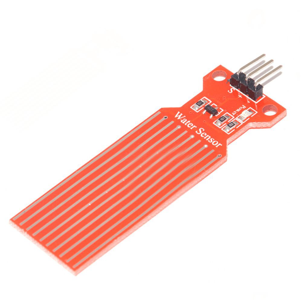
The abstraction layers of Aruna are now looking really nice. When adding a new driver, sensor of actuator you only need to focus on the part that makes it different from other drivers or sensors and can easily inherit existing logic. Lets for example look at the `Rain40x16` sensor driver, this is a sensor that is normally used to measure rainfall in a 40 mm by 16 mm grid, but I use it measure leaks in the ROV.
Rain sensor (Rain40x16) The driver for this sensor is used as a `SIS::Performer`, SIS stands for Safety instrumented system and is used to keep a system (the ROV) safe. A SIS::Performer in Aruna performs safety checks, so that other SIS modules like the SIS::Watcher (bad name) and SIS::Reporter can report the problem to the user, so they can take action. I am also planning to add an automated response (SIS::Response ?) so that the ROV will try to get itself back to a safe state if compromised.
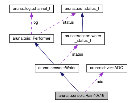
Collaboration diagram for aruna::sensor::Rain40x16 It is of course out of the scope of the rain sensor driver to know anything about SIS, moreover do actions based on the water level. The water level report should be the same for all water sensors, be it a rain sensor as described above or a humidity sensor. The driver should only focus on the part that makes them unique, which in this case is the way of measuring water. The Rain40x16 driver therefore inherits `sensor::Water` to create a standardized interface for water sensors. `sensor::Water` in their turn inherits `SIS::Performer` (can also be used for other task than SIS) and handles all the reporting logic for ROV safety. What also can be seen in this diagram is the use of `driver::ADC`. This is also (like `sensor::Water`) a standardized interface for analogue digital converts.
The great thing about this architecture is that the Rain40x16 driver is hardware dependent (it needs a specific sensor) but is also cross-platform because it does not handle any device specific things itself. But instead relies on the `driver::ADC` that can be implemented for any platform.
//
// Created by noeel on 22-12-20.
//

#include <math.h>
#include "aruna/sensor/Rain40x16.h"

aruna::sensor::Rain40x16::Rain40x16(aruna::driver::ADC *adc): adc(adc) {

}

aruna::err_t aruna::sensor::Rain40x16::get_water_level(uint16_t &water_level_in_mm) {
    int16_t mV;
    err_t e;
    e = adc->read_voltage(mV);
    water_level_in_mm = voltage_to_mm(mV);
    return e;
}

int16_t aruna::sensor::Rain40x16::voltage_to_mm(uint16_t mV) {
//    TODO vcc etc as parameters
    const int16_t sensor_length_mm = 40;
    const int16_t max_voltage_when_dry = 20;
    const int16_t voltage_at_min = 1000;
    const int16_t voltage_at_max = 3300;

    const int16_t voltage_diff = voltage_at_max - voltage_at_min;

    if (mV < max_voltage_when_dry)
        return 0;
    if (mV < voltage_at_min) {
//        voltage is in grey space.
        return 1;
    }
//    TODO this conversion is linear while in real-life it is not
    return ceilf(((float) mV - (float) voltage_at_min) * ((float) sensor_length_mm / (float) voltage_diff));

}
Above is all the code in `Rain40x16.cpp`. The only function it needs to override is `get_water_level(uint16_t &water_level_in_mm)` from `sensor::Water`
The refactoring and redesign of Aruna has so far caused: 78 files changed, 3154 insertions and 2218 deletions. (17 Oct 2020 - 4 Jan 2021). With refactoring of the top layer and documentation of all the modules is still to be done.
Workflow
In other news I have now started to work on unit tests. These buggers can take a while to get right but have filtered some bugs already. Previously I had experimented with Catch2, but that turned out to be too big to run on an STM32F103. And I want to keep a window open to run Aruna on lower end chips (including the unit tests). So now I have written some unit tests in Gtest and Gmock for Actuator(Set) and Link, and I'm going to experiment to run these natively on ESP32 and STM32F103 (they of course already run on X86 GCC Linux).
For a while now I have worked on Aruna in sprints. These sprints always have a (major) goal and are either electrical, mechanical of software oriented. Like the previous sprint was making the Apsu PCB. For months, I have worked on this problem, some times doing nothing else then browse parts and reading my eyes dry on data sheets. I barely touched any software or mechanical aspects of Aruna during that sprint. Because that sprint was electrical oriented, and required my full focus to create a PCB. I remembered that at times I was completely bored by the project and that it felt more like work than a fun hobby learning project. But still I pressed on and got great results as reward. And now I'm facing the same issue with software, in the beginning it was hella fun but after doing the same thing for months its becomes tedious again. I originally used sprint to keep my focus and not wander off-topic, but now it seems that I work less on the project if a boring task is at hand. Therefore, I have decided to do my planning differently from now on. Instead of focusing on one major problem I'm going to cut it in tiny pieces. So I can get more diversity. One of the reasons I like this project so much is because of the diversity in EE (electrical engineering), CS (computer science) and ME (mechanical engineering). But doing only one of these for months make it not so diverse anymore. So next I will be working on some small ME and EE parts before going back to CS, and try to alternate between tasks more.
-
Refactoring Aruna lib
10/26/2020 at 13:50 • 0 commentsBefore adding new features and drivers to the Aruna library I thought it would be wise to do some household and refactor the library a bit. The current architecture consist of 2 layers. One for logic and the other for hardware interfacing.
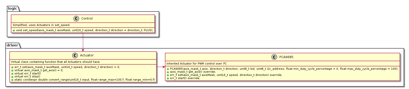
Old architecture. In the image the control module can be seen that is used for moving the ROV. It used the virtual Actuator class. In the image above contains the architecture for the control module. All the PCA9685 specific code rests inside the PCA9685 class that is inherited from Actuator.
A rather simple approach that worked fine in the beginning. But as more and more features get added it becomes repetitive. There are two main problems with this architecture:
- PCA9685 is forced to always be an Actuator, if this same chip is be used for PWM of a LED for example it would result in poor code.
- PCA9685 class needs to be rewritten for every platform I²C driver, despite the PCA9685 driver logic staying the same.
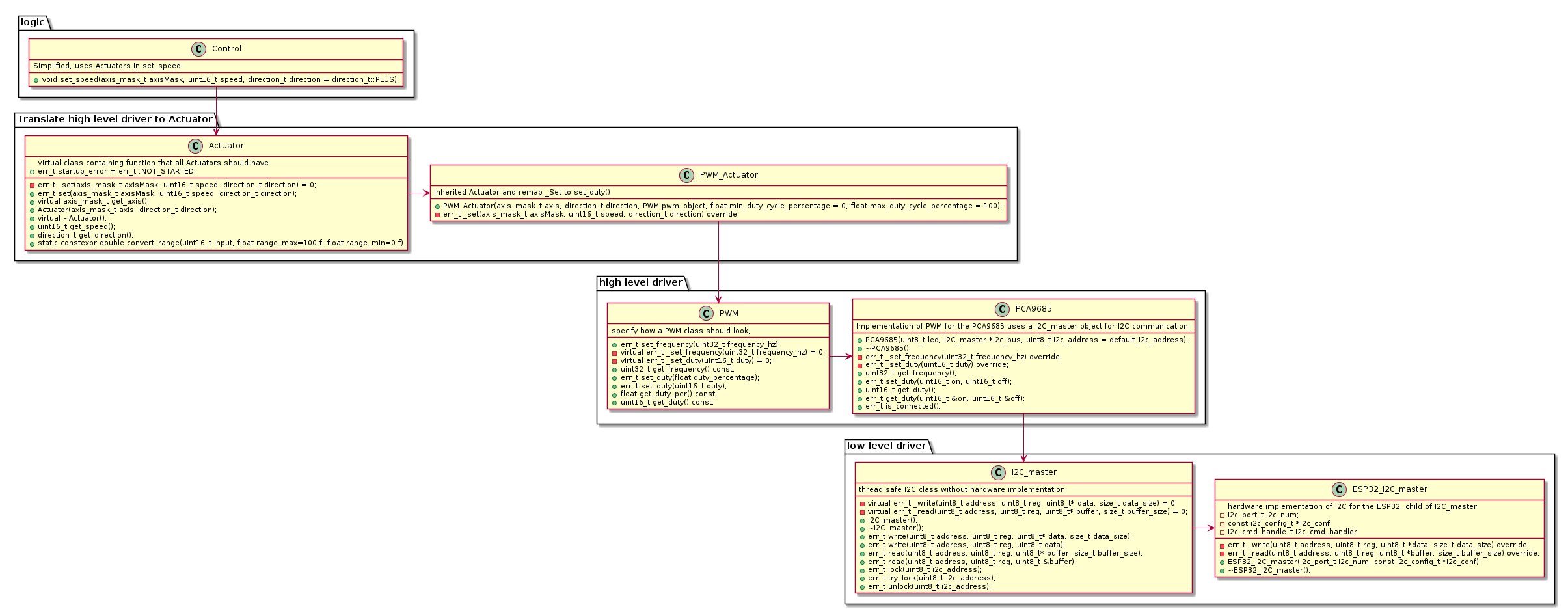
To mitigate these problems extra abstraction layers are added between the Actuator and the I²C code resulting in 4 layers:
- Control logic
- PWM Actuator
- PCA9685 driver
- I²C driver
New four layered architecture. Separating the PCA9685 driver from hardware or software specific code. With the addition of the high level driver layer the PCA9685 driver is now free from hardware specific I²C code because that now rests in the I2C_master implementation. Instead of being hardcoded to an Actuator object the PCA driver is now a PWM object and free to be implemented in any module being an Actuator as shown above or an LED or what not.
A new implementation of PWM (for example the ESP32 native PWM) can easily replace the PCA driver and the layers above would function as if nothing happened. Also porting to a new platform is easier as only the I2C_master class has to be written, all the other code is portable (given an POSIX OS).
I have not yet written the PWM_Actuator code but while making this graph I thought to maybe let PWM inherit Actuator. That makes things easier when using the code, and we are not limited to one parent because C++ supports multiple inherits. So any module abstraction can be added later when needed. But it might make PWM bloated, not sure yet what to do. Atlas I'm first going to focus on more refactoring because although the architecture is now much more flexible this is not yet the case for the other modules (comm and blinky). And some internal structures like `direction_t` for given direction feel redundant because I much rather make use of a singed integer.
I have also been looking into ROS 2, I might make an Aruna ROS package. But that's all in the far future. Nevertheless, I really like their pub/sub model and I might implement something similar for the comm module. I also think that using a simulator could really benefit the development of the project. But I'm indecisive about Gazebo or Webots. Unit tests and better code quality will be worked on first though.
-
Future roadmap
10/04/2020 at 19:50 • 0 commentsWith the Hackaday 2020 prize drawing to an end (and with my submission video uploaded) I thought it might be a good idea to talk about what I'm planning to do next for the Aruna project. Please note that these are ideas of mine and might not be implemented in the order written down or even ever.
Short term (working on this right now)
- Write drivers for all components on the PCB.
- Write unit tests for all functions of the Aruna library
- Refactor Aruna library to be more consistent
- Refactor all FreeRTOS from Aruna library to 100% Posix.
- ROV visualization with Inar (the control module at the surface)
- Xbox controller support for controlling the ROV
Long term (going to work on this probably next)
- Water quality sensor (for plastic levels etc.)
- Integrate the "dop" into the core
- Make a detachable cable plug
- Write a Dshot driver for the PCA9685, buy 4 more BLHeli controllers and get rid of the SimonK.
- Add two more motors to the design to create a 6DOF model
- Create a ballast tank
- Design a more space efficient Apsu board V2
- Make an automatic fail-safe, so that when the ROV crashes it can return to the surface anyway.
- Redesign the "universeel houder" because it required an odd position for screwing.
Hope and dreams (Far future)
- Sonar
- Camera
- Robot arm (for scooping soil)
- More efficient (maybe bigger) rotor blades
- Subsistent for BLDC, because these rust.
- Low frequency radio communication with the ROV (~27MHz)
- Implement an Aruna ROV for the STM32 and embedded Linux
- AUV (Autonomous underwater vehicle)
- Cross the IJsselmeer (the biggest Dutch lake)
- Create an underwater glider
-
Diving into the canals
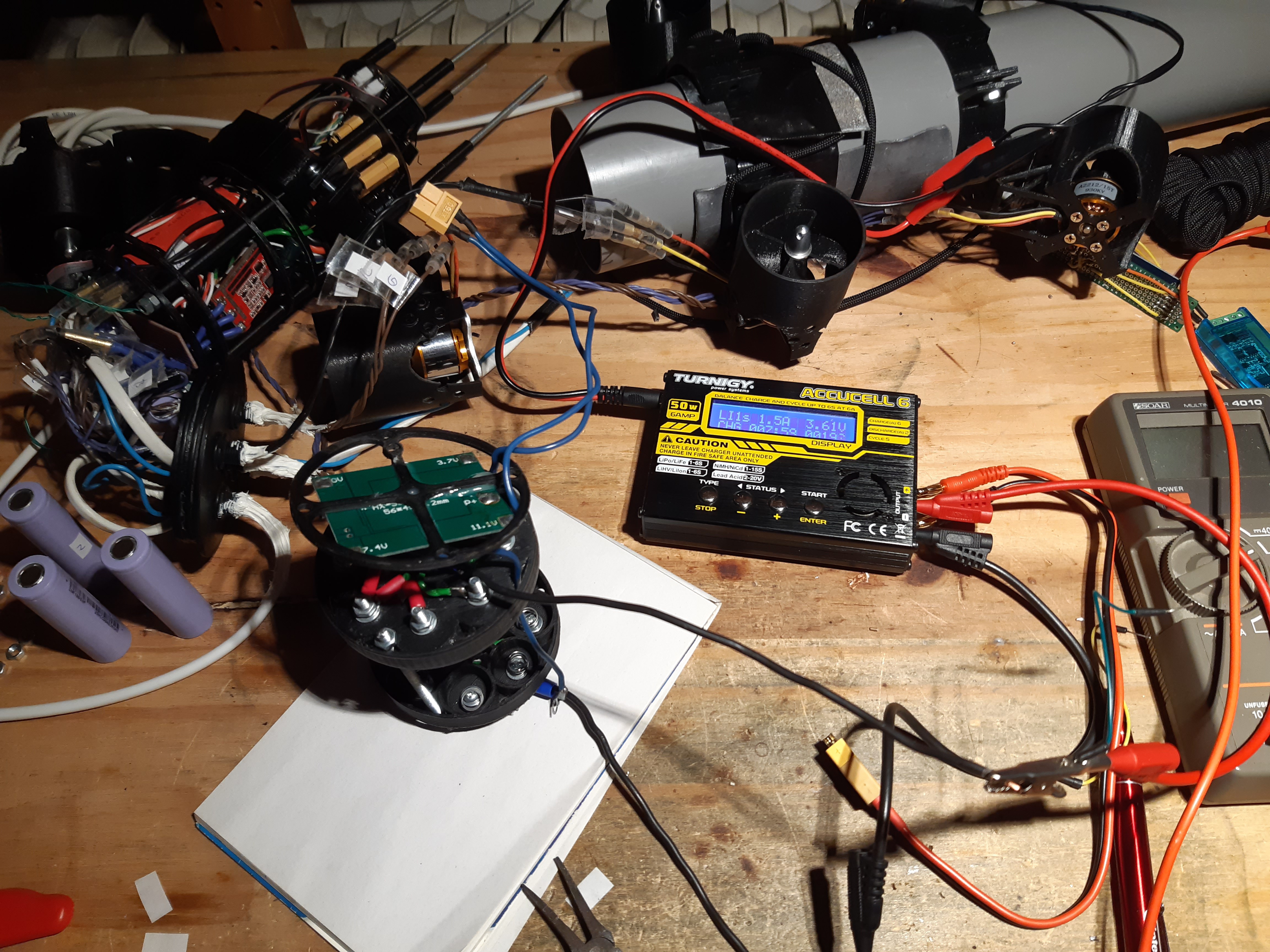
10/01/2020 at 11:06 • 0 commentsNow with the core of the ROV assembled it was time to test in uncontrolled waters: the Dutch canals. After fully assembly the ROV; turning it on and testing it. It turned out that a 18650 battery cell was broken. The total battery pack measured 7.4V, yikes. Lucky I had a spare cell, so after a day of charging (I had to do a lot of swapping since all the cells had different voltages) the battery pack was full at 12.4V :).
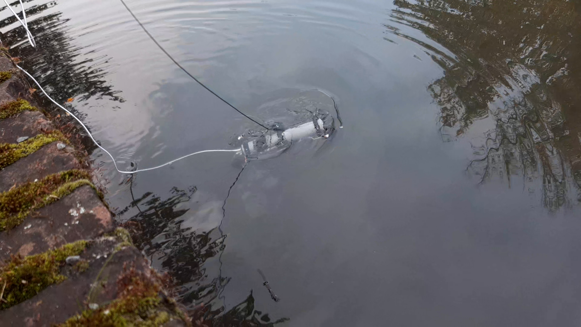
Charging 18650 cells using a charger Doing the dive into uncontrolled waters was exiting as it was the first time outside the bathtub. The previous bathtub test was in May and a lot has changed since then. I really didn't want my PCB to get soaked. While diving, I noticed that the balance was a bit off and that it was back heavy. In the next iteration I want to make a more adjustable weight system, instead of having two pieces of lead taped to the PVC pipe. I might also add a fin for stabilization.
ROV in the canal, will upload a video shortly After diving with the ROV for a while the fuse broke on the power board broke. I found this rather odd because the fuse is rated at 5A. And when I did a stress test (four motors full throttle) on the motors they came at 3A max. After inserting a 6.5A fuse it broke almost immediately. I couldn't detect any shortages and the system worked (on land) with a small fuse (1A, two motors) at half throttle. The water could add an extra resistance for the motors so that they require more power, more testing is required.
Broken fuse I'm busy with the video for the Hackaday prize featuring the dive described in this log, so keep an eye out for that.
-
Shortage and assembly
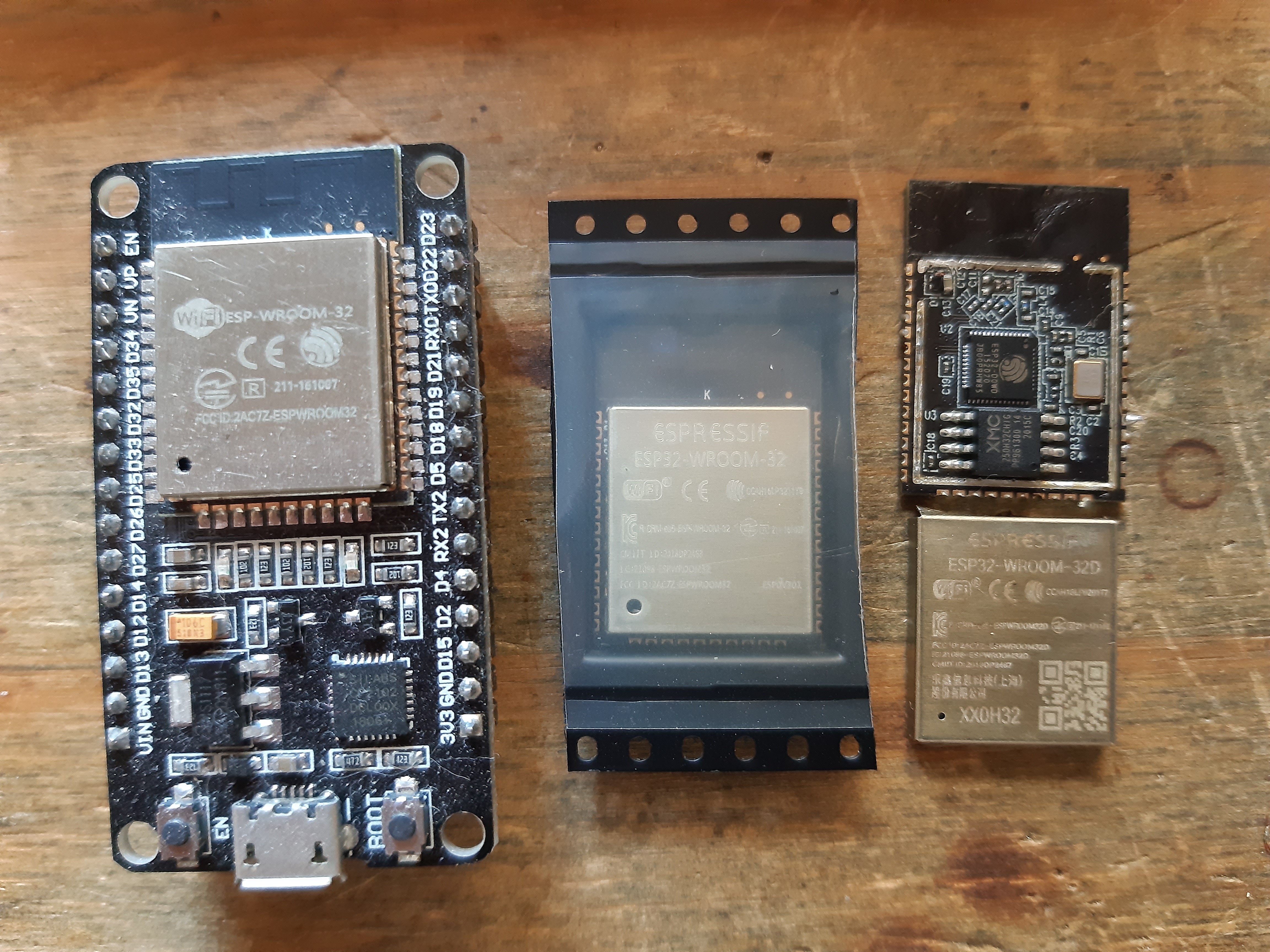
09/26/2020 at 12:28 • 0 commentsAfter finishing writing the driver and confirming that it was working with my logic analyser I connected my SimonK ESC. Unfortunately The ESC weren’t armed by the PCA PWM signal. I tried changing the frequency of the PWM from 200Hz to 50Hz. But no dice, after that my FT2232H JTAG debugger could no longer connect to my ESP. It kept saying “could not halt device: not initialized” (or something similar, I’m typing this from memory). It turned out however that there was a short between my ground and power (~20 Ohms). But I did not know where. I first assumed it was the PCA9685 since it was directly connected to an external chip and had experienced mayor re-routing.
Left to right: ESP-32 dev board, new ESP32, shorted ESP32. All with different markings After desoldering the PCA9685 the short was still present. I removed the ESP and that mitigated the issue. Luckily I had a spare ESP-32 chip however, I messed up the SPI-SS0 pin. So SPI communication will be a little difficult. But that will be an issue for later.
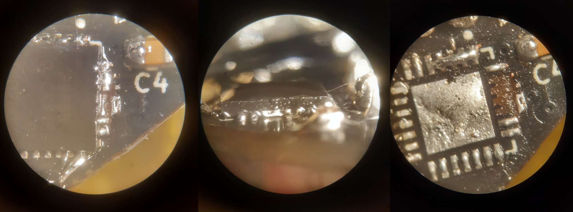
After measuring the PCA it turned out to be fine. So I tried to reinstall the PCA chip with all its tiny rerouting. This however did not succeed and I ended up destroying three more coper pads.
PCA9685 resolder attempt. Left shows top-down of the IC, middle side view and right picture with the IC removed Since the PCA was beyond repair this time I opted for my second option discussed in previous log; to buy an PCA9685 breakout board. While connecting this to the Apsu board I was afraid that the shortage that happened earlier would strike again. I’m still uncertain why the ESP chip failed earlier. So I measured the PWM signals coming out of the SimonK ESC’s. And they all measured ~5V. This is possibly because they are pulled-up and should not pose a problem since the PCA9685 supports 5V logic levels (while it's still driven by 3.3V). After connecting everything together I was finally greeted with a spinning motor :).
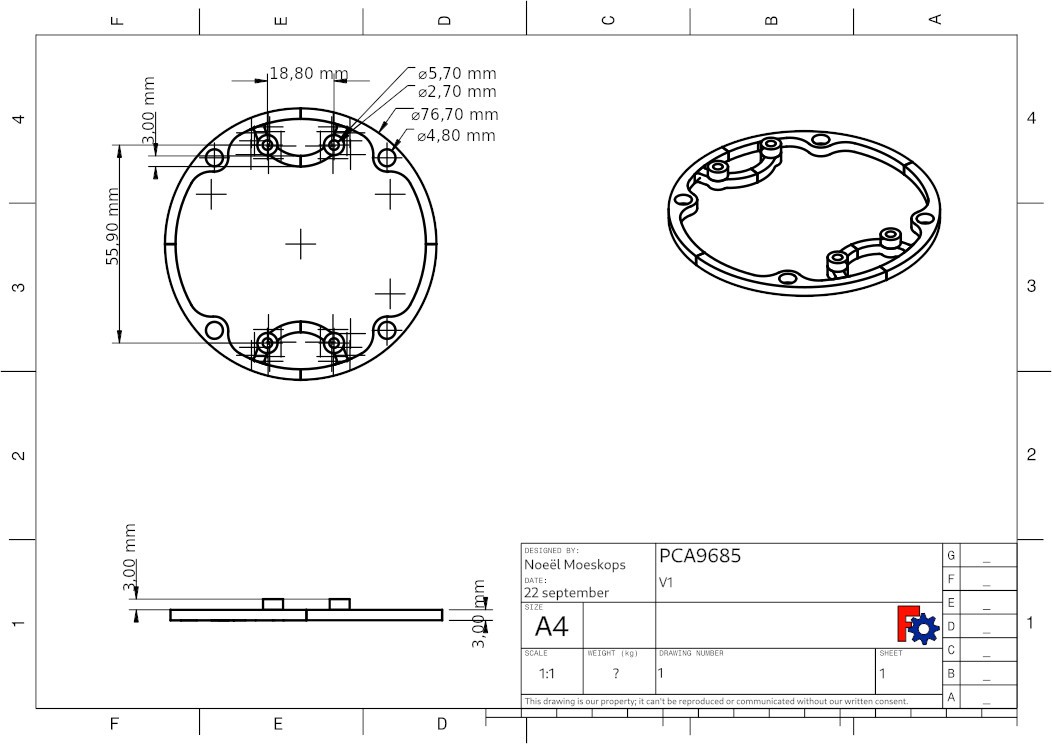
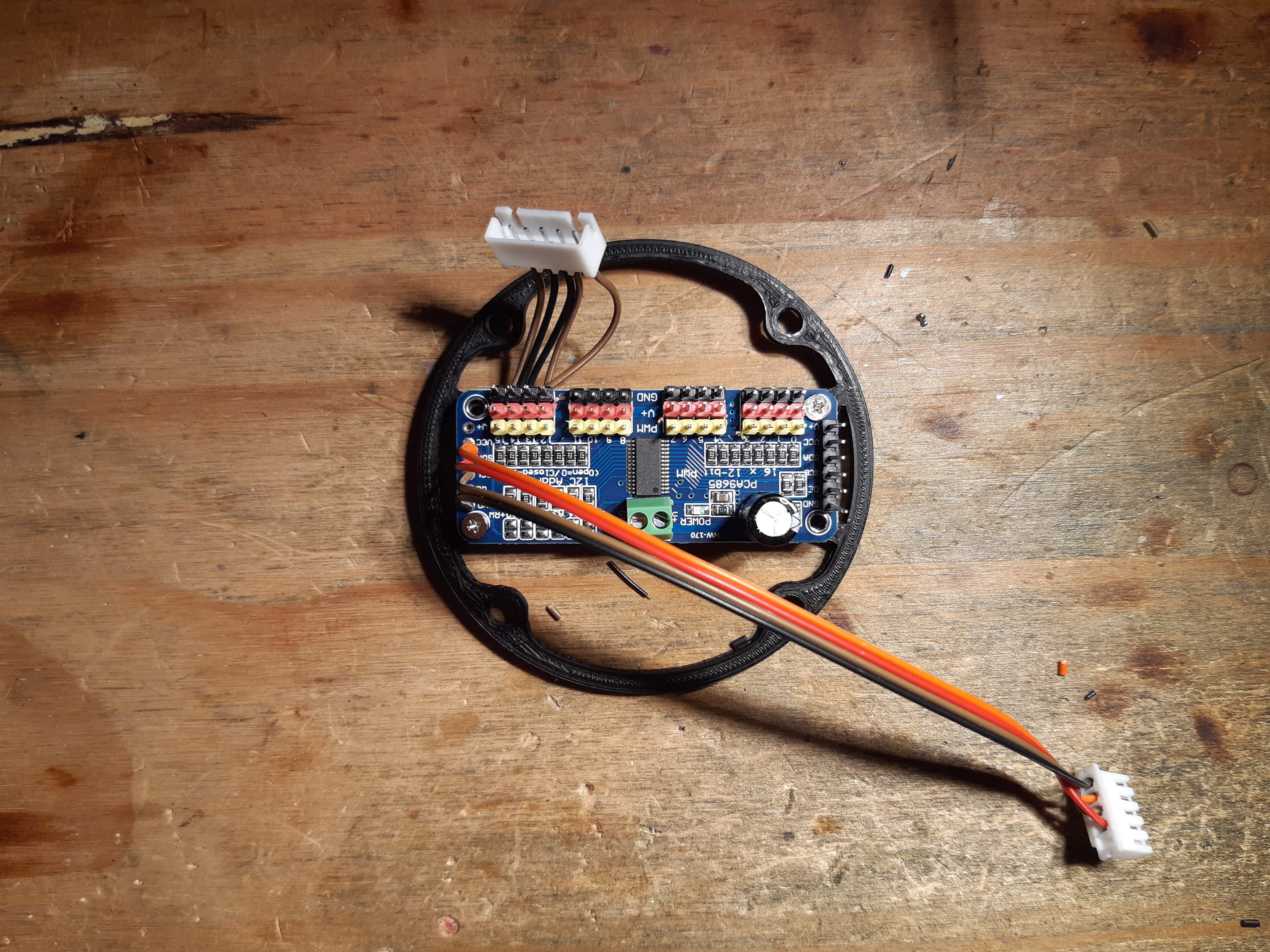
To enable the PCA9685 breakout board to fit into the tube of the ROV I created a holder for it. It looks very similar to the water holder breakout board I created earlier.
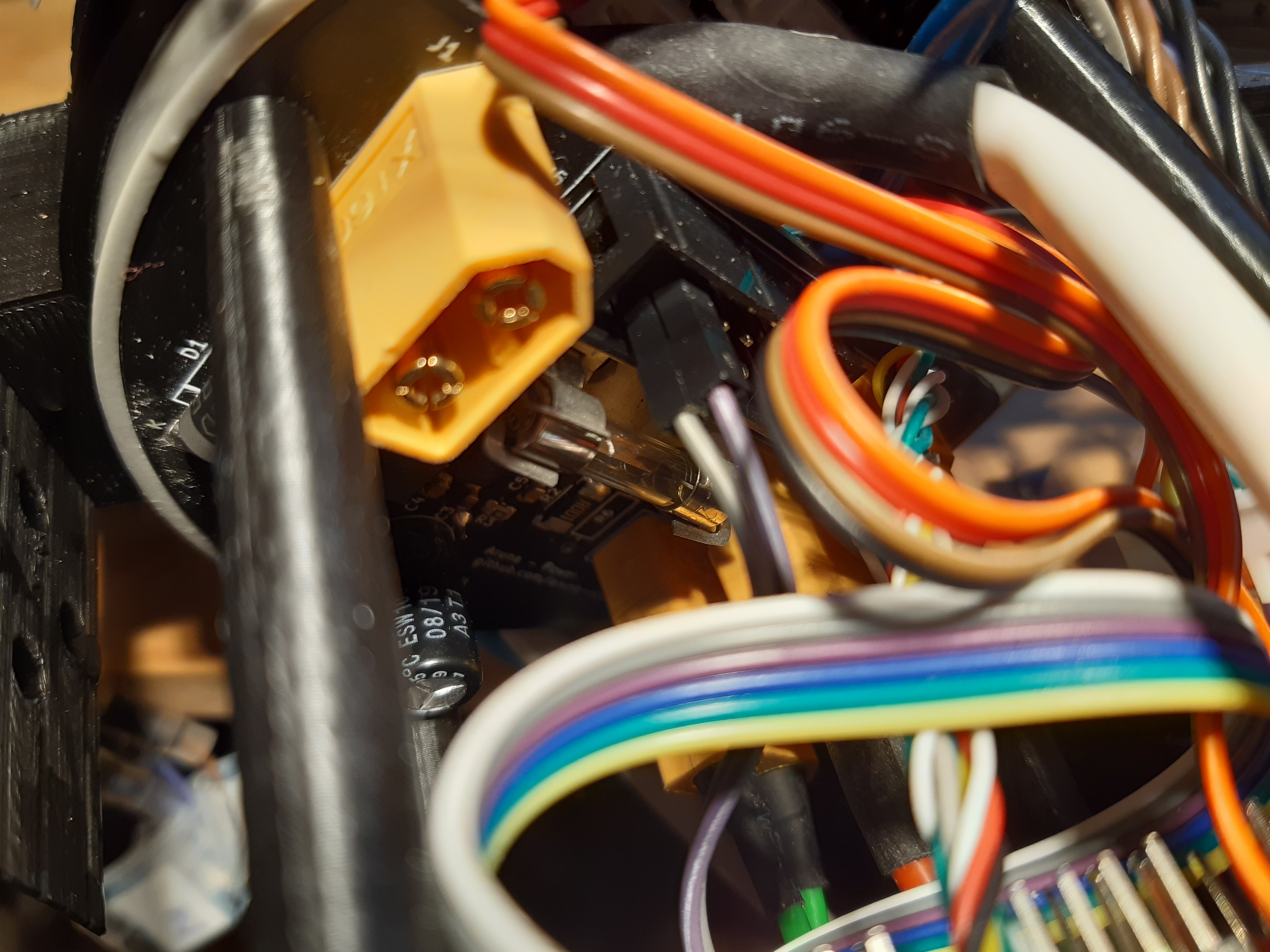
With everything working now the next step is to put everything together so it will fit into the tube again. Curiously the total size of the assembled core (I am going to call the electronics inside the tube core from now on in lag of a better word) is 3 cm larger than previously! I hypothesized that it would be smaller. But because of the extra space the XT60 cable takes around 4 cm is lost (notice the space between the power and the PCA9685 board). This is something I will have to reconsider in the next PCB design, because the PCB’s itself are very space aware the connections however, are not. I’m planning to put smaller side facing connections on the next iteration.
Left to right: Battery, BMU, Apsu board, power board, PCA9685 board, BLHeli, 4x SimonK, water sensor -
PCA9685 driver
09/21/2020 at 09:17 • 0 commentsRegisters
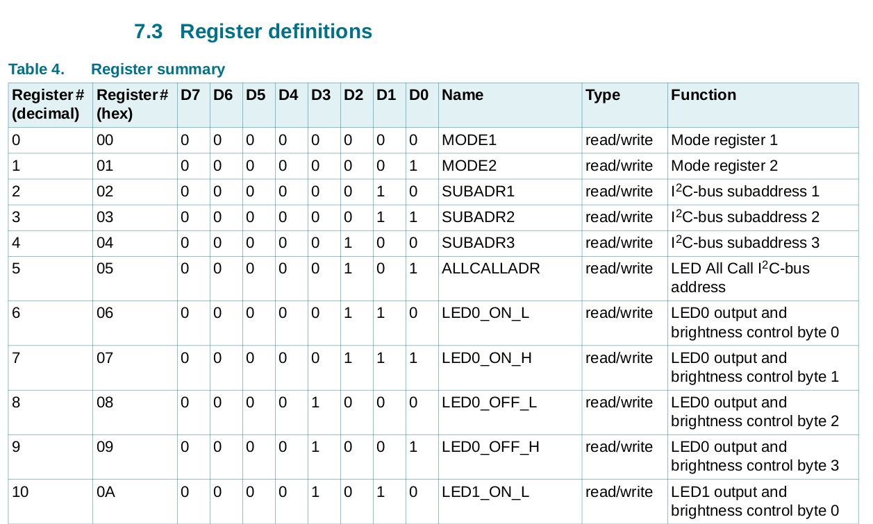
After looking at the data sheet for the registers it turned out that the device is pretty simple. At startup the IC is in low power mode, after setting it to normal operation mode the PWM of each pin can be set.
Some registers from the PCA9685 data sheet The register MODE1 contains settings to restart the IC, use external clock, power mode and set broadcast mode. MODE2 is less significant and contain some specific settings for I²C communication and PWM configuration, like putting the output pins to open-drain or totem pole(?). On address 0x6 the PWM output starts. (called LED because this IC is designed for driver LEDs, motors will also work fine).
So when writing to register 0x6 the PWM can be set by first specifying the time when the PWM needs to be turned on (0-2048, because register *_L and *_H are together 12bits) and then the time when the PWM needs to be turned off. The time is specified between one clock cycle. The clock of the outputs needs to be set separately and is the same for all the outputs.Driver
Since PWM is such a common peripheral I created an abstract driver in the `aruna::driver::PCA9865` namespace.
// include/aruna/control/PCA9685.h

/**
 * Set the PWM of an output of the PCA9685
 * @param led, 0-15 output to adjust
 * @param on, 12bit time to turn on
 * @param off, 12bit time to turn off
 * @param address, I²C address of device, default 0b1000000
 * @return
 */
err_t set_pwm(uint8_t led, uint16_t on, uint16_t off, uint8_t address = default_address);
This is currently the only function that I wrote yet, very minimal. I want to create a working model as quickly as possible. Its actually only a header. Its Upton each platform to write an implementation for it. The ESP-32 implementation is found at `./src/driver/PCA9685/portable/ESP32/PCA9685_ESP32.cpp`.
To enable this driver to work seamlessly in place of my previous PWM driver (that uses the GPIO pins on the ESP) I had to create a wrapper of sorts for the `Control::Actuator` class. `Control::Actuator` Is a virtual class so that the control module have a common interface to control actuators on the ROV. Multiple actuators of different natures can be used at the same time.
// include/aruna/control/Actuator.h

/**
 * Set the speed of the motors directly
 * @param axisMask, multiple axis to apply speed to.
 * @param speed, speed of the motors
 * @param direction, direction to go to.
 * @return err_t::OK if the command was succesfull, others when it fails.
 */
virtual err_t set(axis_mask_t axisMask, uint16_t speed, direction_t direction) = 0;
The `set(...)` function is the only required function of an `control::Actuator` class driver implementation. `axis_mask_t` specifies the axis that needed to be driven (X, Y, Z, Roll, Pitch and Yaw). If a given driver can't perform a given axis transformation it wil just return.
This layered driver structure allows me to quickly switch between hardware.
// include/aruna/control/PCA9685.h

/**
 * PCA9685 I²C PWM driver
 * @param axis: supported axis masks
 * @param direction: supported directions
 * @param led: PCA9685 LED output number (0-15)
 * @param i2c_address: address of the PCA (default 0b1000000)
 * @param min_duty_cycle_percentage: minimal duty on percentage (default 0)
 * @param max_duty_cycle_percentage: maxumal duty on percentage (default 100)
 */
PCA9685(axis_mask_t axis, direction_t direction, uint8_t led, uint8_t i2c_address, float min_duty_cycle_percentage = 0, float max_duty_cycle_percentage = 100);
Above shows the constructor for the PCA9685 `Control::Actuator` driver. As required by the parent class it needs to be supplied with an axis mask and direction. Other parameters are specific for the PCA9685. Although I took a peek at the ESP32 native PWM driver that I have written earlier and copied `min/max_duty_cycle_percentage`. This is needed for the SimonK driver as it operated within 5-10% of the PWM signal.
Each actuator needs to be registered by the control module by executing `control::register_driver(...)`. Then (after the control module has been started with `control::start()`) all the actuators can be controlled simultaneously with `control::set_speed(...)`. The control module also features some more abstractions, cool features and manages the input from the surface but that's out of the scope of this blog.
// include/aruna/control.h

/**
 * register an accelerator driver for use.
 * @param driver pointer to the driver
 * @return `err_t::OK` if it went well.
 * `err_t::FAIL` if not.
 */
err_t register_driver(Actuator *driver);

/**
 * initialize control and communicate with hardware for active modes.
 * @return status_t, returns current status of the module
 *  * `RUNNING` if it is running,
 *  * `STOPPED` is it us currenty stopped.
 */
status_t start();

/**
 * Set the speed of the motors directly
 * @param axisMask, multiple axis to apply speed to.
 * @param speed, speed of the motors
 * @param direction, direction to go to.
 */
void set_speed(axis_mask_t axisMask, uint16_t speed, direction_t direction = direction_t::PLUS);
There is still some work to be done with this infrastructure, driver layout and especially the PCA9685 implementation as it is a bit rushed at the moment and it has not all the abstraction layers that I would like to see. (like the I²C abstraction that I talked about earlier).
In the next blog I will discuss the testing of the driver and the assembly of the ROV.
See the relevant Aruna git comment and Apsu git comment for more details.
-
Getting the PCA9685 to work
09/12/2020 at 23:16 • 0 commentsIn the PCB tests log I talked about having the wrong layout for the PCA9685 IC (I used the TTSOP28 pinout with the HVQFN28 package). In order to solve this I considered four options:
- Cross wire and cutting traces to connect the correct pin.
- Buy external PCA chip
- Design breakdown board for the PCA.
- Designing Apsu PCB V2
I kinda wanted to have PWM control as fast a possible because its such a vital part of the ROV. So I opted for the first option of cross wiring the IC, because it could be done within one day (or, so I thought).
Of the total 28 pins of the PCA chip only 9 vital (+4 non vital) pins needed to be rerouted:
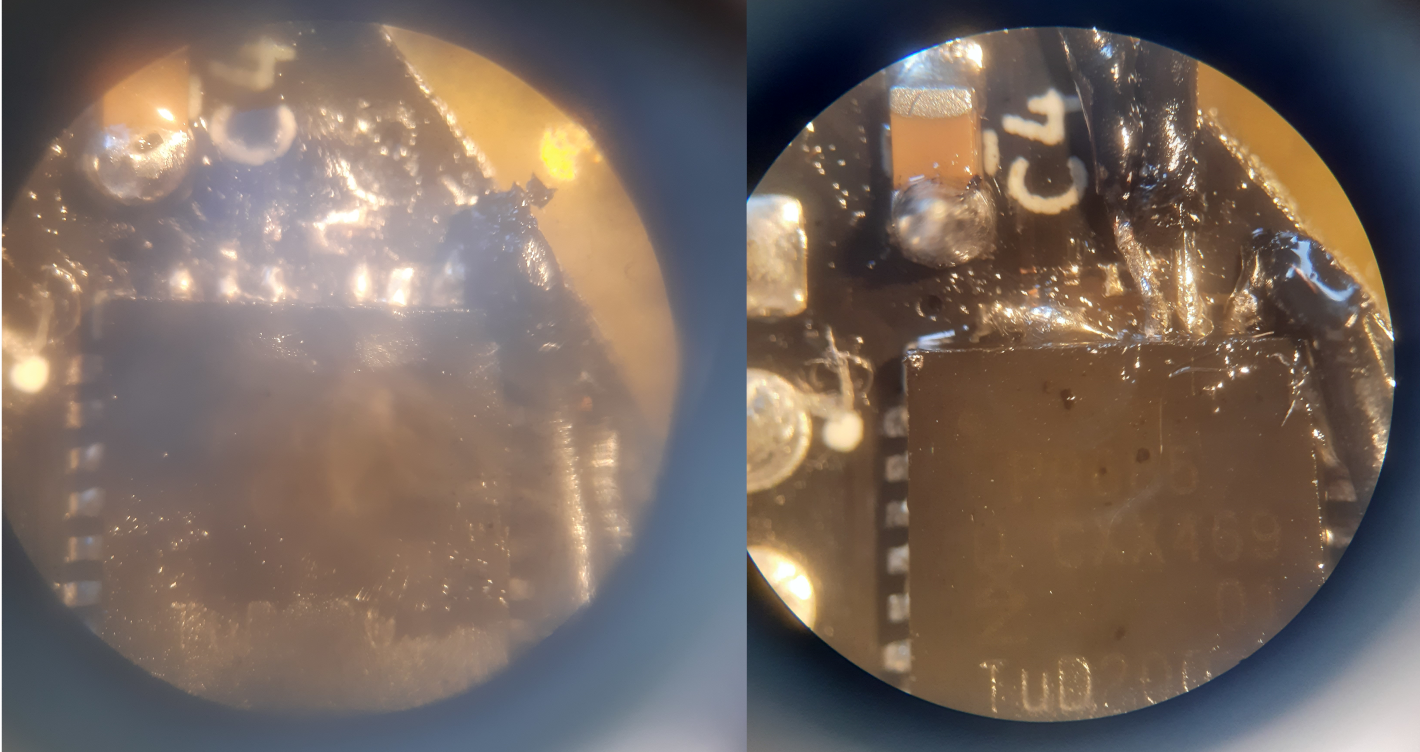
pin nr. PCA9685PW/TSSOP28 PCA9685BS/HVQFN28 11 led5 VSS 20 led13 ~OE 21 led14 A5 22 led15 ext clock 23 ~OE I²C SCL 24 A5 I²C SDA 25 ext clock VDD 26 I²C SCL A0 27 I²C SDA A1 Left: VCC (pin 25) copper pad destroyed. Right: finished resoldering Soldering wires on the tiny connections was a frustrating task. The pad of pin 25 (middle pin in the left picture) was even broke due to extensive heat. And I also broke a solder tip (don't ask how). Luckily I managed to solder directly to the IC and connected pin 25, 26 and 27 to VCC. As can be seen on the right picture.
Finished rewirering. Now I finally understand why sci-fi films have wires sticking out of their PCB's! While cutting the traces I however, also cut the I²C-SCL trace. I didn't notice it at first and thought that I blew up the IO pin on my ESP somehow. So I needed an extra wire going from I²C-SCL directly to the ESP (top wire on the picture). After the complete rewiring the PCA now has the address `0b1100111`. And the Adafruit PWM library finally was working properly.
Four PWM signals after successful I²C communication The back of the PCB is really getting seasoned, but I'm very glad the chip is working now. Now I'm off to write a driver. -
testing INA219 & MAX6682
09/10/2020 at 12:14 • 0 commentsINA219
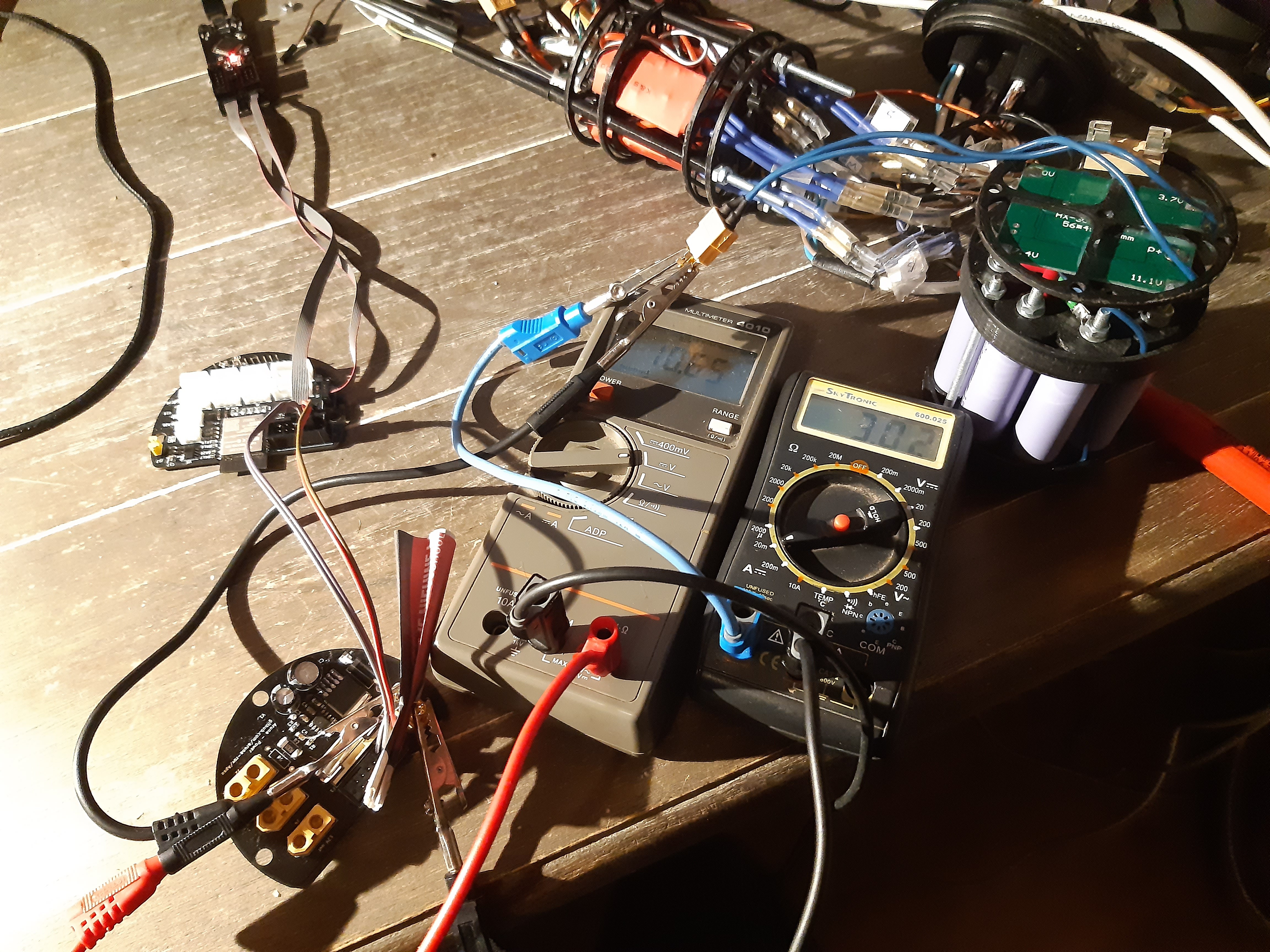
The INA219 is positioned on the power board to monitor the voltage and current of the 12V battery pack, communication goes over I²C. I used an Arduino sketch to test this sensor and it all worked the first try.
Multimeter left showing voltage (10.65 V) and multimeter on the right showing current (3.02 mA) To monitor the correctness of the measured data I placed two multimeters in the circuit to measure the voltage and current. The left multimeter measured the voltage at 10.65 V. This is only a difference of 0.03 V between the control and the INA219 chip. The right multimeter measured a current flow of 3.02 mA. The INA measured a current of 5.40 mA, this is quite a big difference. But it is consistence with the difference of the voltage measurement: 0.03 V and ~0.02 A. The current is now ridiculously low because the components are also being powered by the debugger. When the debugger is disconnected the current rises on the multimeter. Because the UART of the FT2232H board I use also supplies power to the board is it difficult to get an accurate measurement. Later, when I write a driver for it, I can communicate the current over RS485 this problem would me mitigated and some proper testing with motors in place could be done. But so far it looks functional.Bus Voltage: 10.62 V Shunt Voltage: 0.54 mV Load Voltage: 10.62 V Current: 5.40 mA Power: 59.00 mW
Serial output of the example code above.
MAX6682
The MAX chip converts thermistor temperature to digital data over SPI. This comes in handy for my external thermistor (YC100665). The chip takes care of self heating and power-supply noise and supplies a read-only 10bit SPI signal, very straight forward.
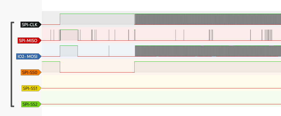
After reading the SPI documentation of the ESP-IDF it turned out that my assumption of "ESP-32 supports every hardware operation on every IO port" was incorrect. It turns out that there are two SPI IO sets for the ESP: HSPI and VSPI. HSPI is already in use by JTAG so only VSPI is left for mortals. Not using the VPSI pins is possible but at lower speeds and more delay. So not a total loss I though, until I found out that I was using an input only pin for the MOSI :( (also for one BLHeli Dshot output pin, but that was redundant anyway). I changed the MOSI pin to IO2, since that was the only pin left, so I could at least still test the chip.
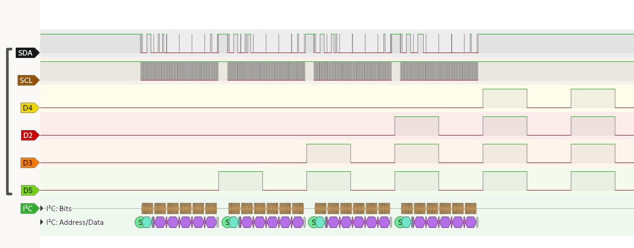
The Slave Select pin of the MAX6682 is connected to an output of an MC74HC138A demultiplexer. This allows for up to eight devices on the SPI bus by using SS0-2 pins for chip selection. My luck turned here and I could successfully read the MAX6682 via SPI (no thermistor attached).
Looking at the logic analyser the data does not seem to make a lot of sense. At least the MAX6682 is outputting data on the MISO line. More testing with the sensor attached needs to be done. But I'll leave that for later since I want to focus on more essential things first.
-
Documentation and license
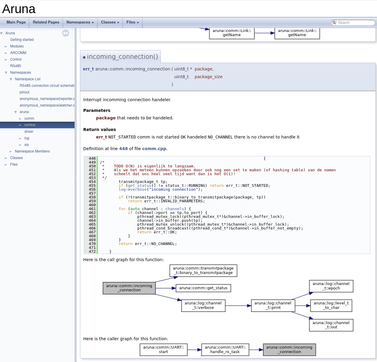
08/28/2020 at 12:42 • 0 commentsDocumentation of the Aruna library is now hosted on Codedocs.xyz. The documentation gets automatically updated after every push! They unfortunately don't support call graphs, so you will have to generate the documentation locally if you want to easily see how everything gets called. I might reupload the documentation somewhere else at some point that does support `dot`.
Locally build documentation with call graph
I also added the GNU GPLv3 license for all the repositories in the project.
Aruna - ROV
Modular ROV for underwater exploration, discovery and monitoring