-
Finished the Metal Work
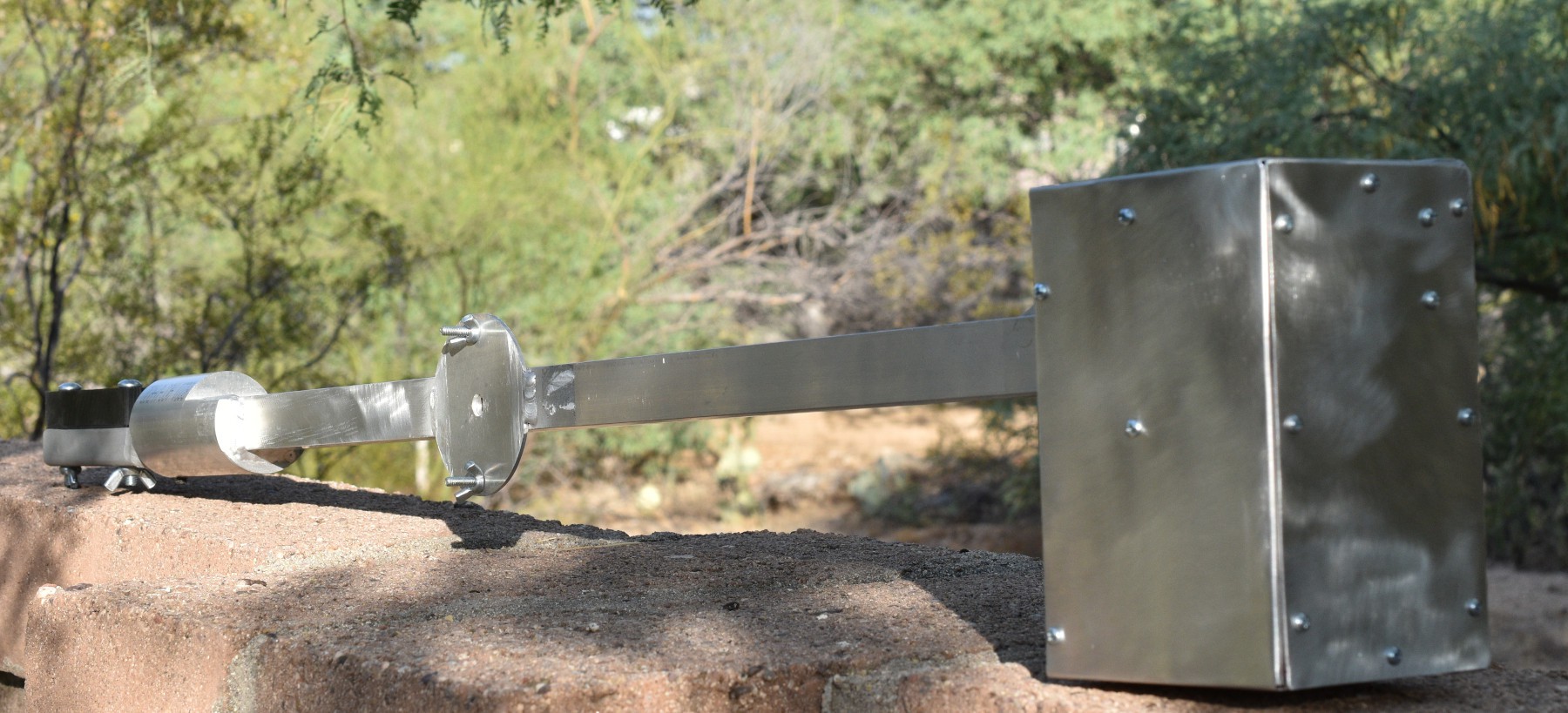
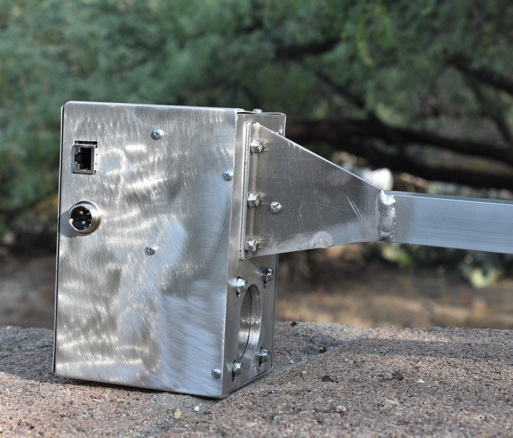
06/27/2020 at 15:29 • 0 commentsInstalling the new board in my previous project #Satellite Antenna Rotator Mechanical System required some sheet metal work. I wanted to re-use as much of the existing system as I could, but move the external step motor and it's wiring into a closed up box. Here is the completed antenna arm.
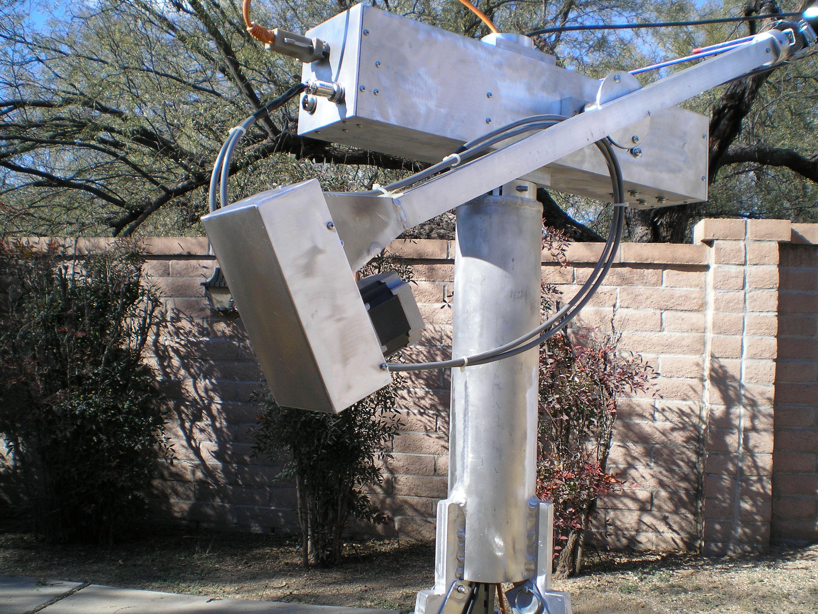
Completed Antenna Mount Arm The original design has the step motor outside the box, with the drive pulleys, belt, and theta home sensor inside the box. The motor drive signals and theta home sensor wiring can be seen going to the main body of the rotator.
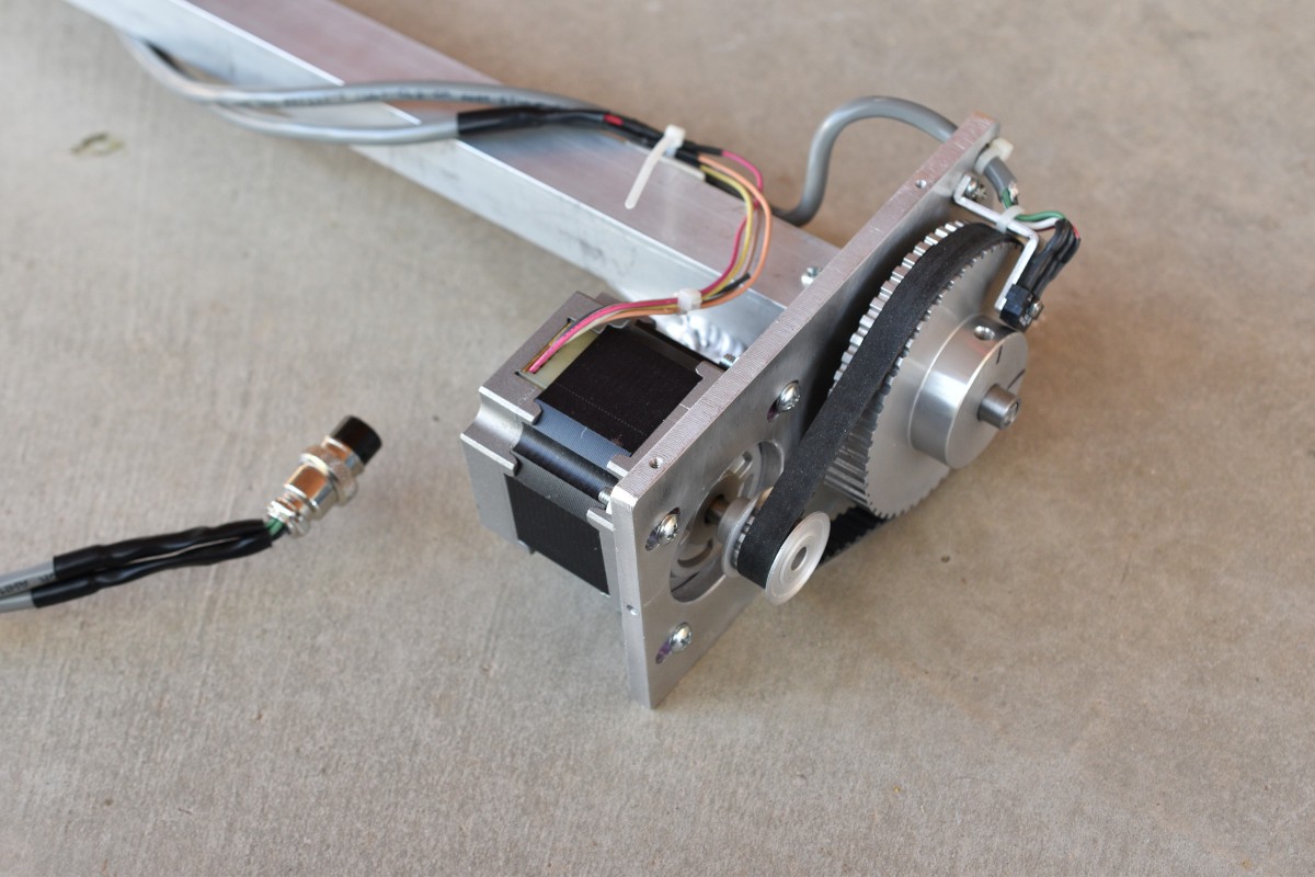
Original Design of Antenna Mount Arm with External Theta Motor and Wiring. Here is a picture of the original design theta mechanics.
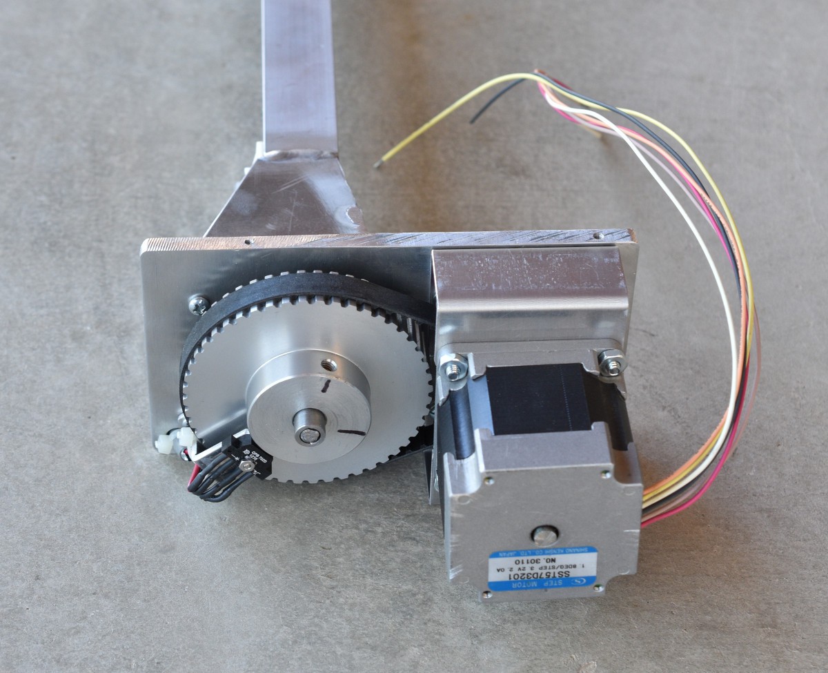
Original Design Theta Mechanism and Wiring. The only new mechanical parts that had to be designed and made for this modification are a motor mount bracket and the new box. Here is the new motor mounting arrangement with the new brackets.
New Design Theta Mechanism In both designs, the theta home sensor is a photo-reflective sensor that looks for the set screw hole on the driven pulley.
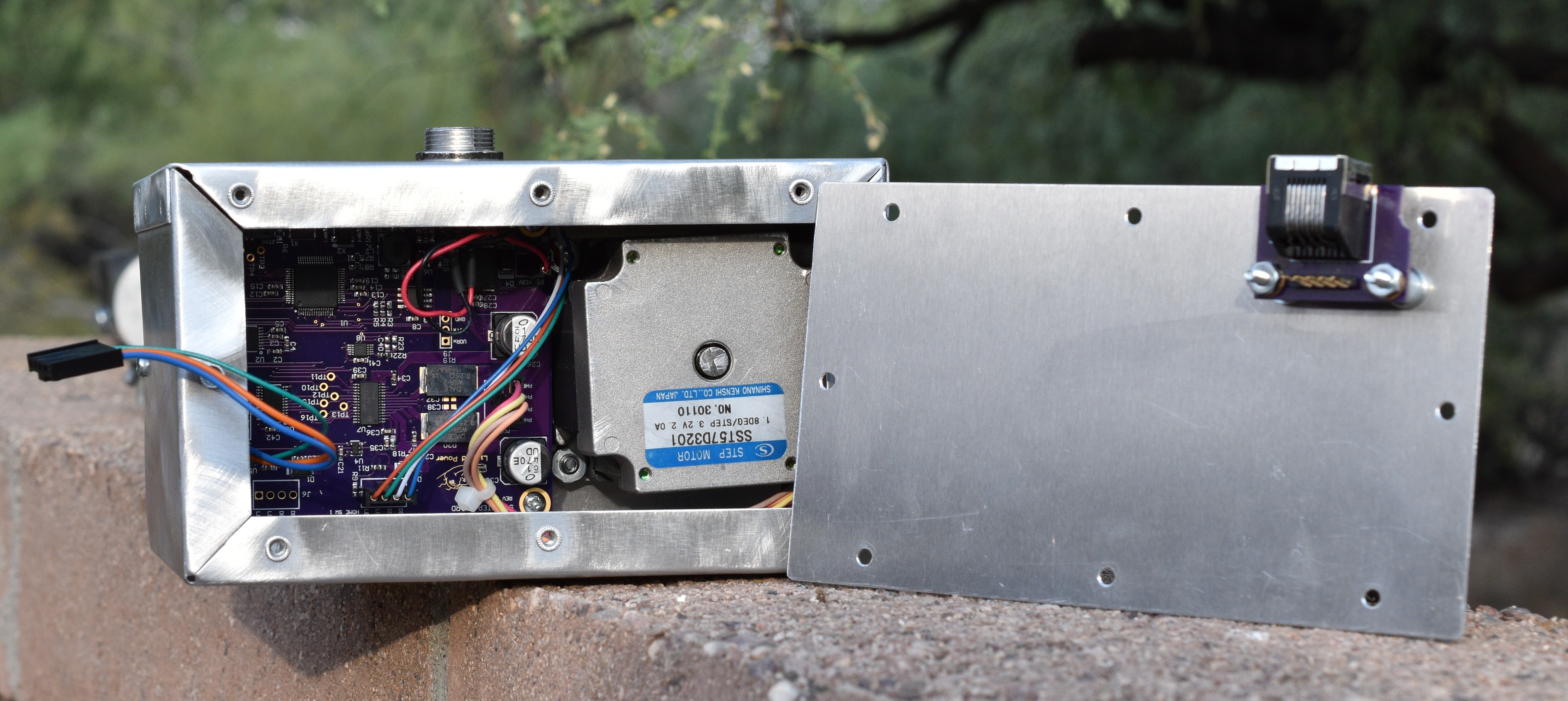
Looking inside the box on the modified theta mechanism, you can see the motor and the control board. The control board is mounted to brackets on the sides of the box. There is not much extra space inside the box. It would have been possible to make the whole theta head larger, but that would have required a lot of extra machining to make a new base plate and was not really necessary.
Theta Mechanism Box Inside View The control interface to the new theta control uses an RS232 serial physical layer. The RJ45 connector is used for that RS232 connection because they are a nice small connector that has a positive lock for the cable. A standard network cable has 8 wires in it, so a single cable can carry the control link for the azimuth/elevation control board and the theta control board. A small PCB with two RJ45 connectors and a header connector was bolted to the main body of the rotator to break out the azimuth/elevation control link from the cable and pass the theta control link on to the theta board. Due to the mounting arrangement on the RJ45 jack that I used, it was easiest to mount it's PCB to the top cover of the enclosure. The cable sticking out of the left side of the enclosure mates with the header connector visible below the RJ45 jack. Nut inserts are used for the cover mounting holes because sheet metal screws shed small bits of metal and strip easily.
Power for the theta axis comes in via the 2 pin circular connector shown just below the RJ45 jack. Because this project was motivated by reducing the EMI radiated by the exposed step motor wiring in the original design, I took extra care in designing a filter for the input power to the motor control board. The DC power and RS232 links are the only connections to the theta head. On the right side of the box, the external step motor mount hole is visible. I designed a bracket that flips the motor over and covers the old mounting hole. The new bracket uses the old belt tensioning adjustment slots visible in the base plate.
-
Built a scond board up
06/18/2020 at 21:33 • 0 commentsThe Theta Axis project that I designed this board for is going to be a close fit to get everything into. In the interest of easy assembly, I built up another one of these boards, but instead of the little 2.54mm screw cage terminal strips for the power, motor and home switch, I put 2.54mm Molex Cgrid III connectors in. I have a crimper for the pins for that line of connectors and they work well for applications like this. Another advantage to these connectors is that there is no side access required for assembly, just push the connector onto the pins and go.
The new board built up with no problems. The only issue that I had when I powered it up is that I had the EEProm write protect pull up resistor populated and the firmware complained about not being able to write the EEProm. I pulled the resistor and all was well. I made the same mistake on the first board and marked the electronic copy of the schematic but forgot to mark the hardcopy of the schematic. That is fixed now.
Single Axis Step Motor Controller/Driver Board
A Complete Step Motor Controller and Driver Board
 Bharbour