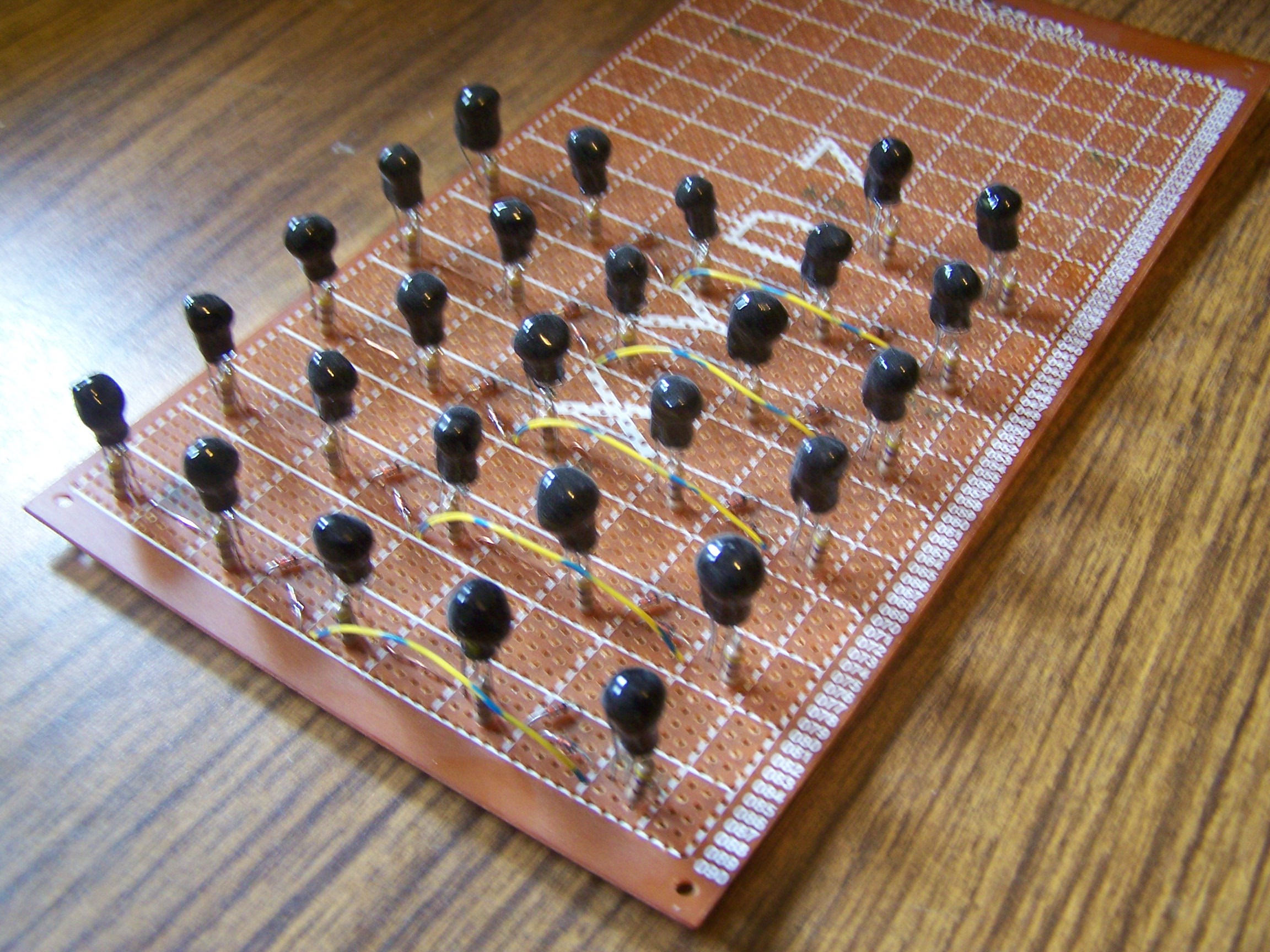
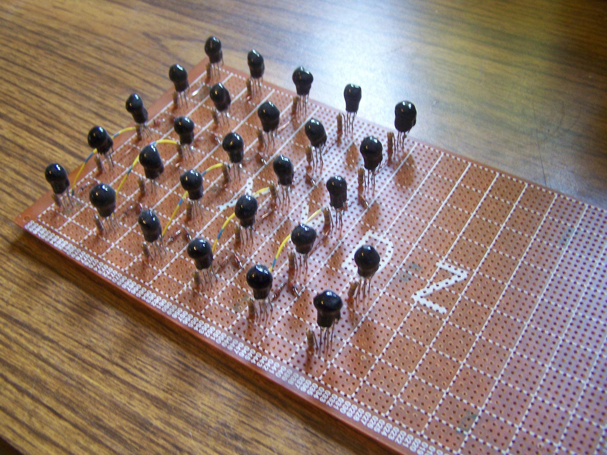
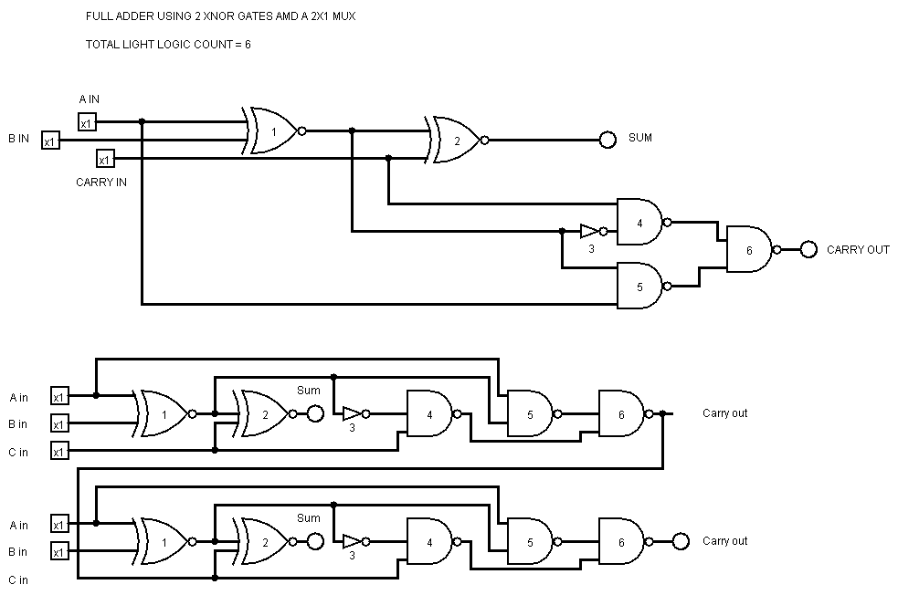
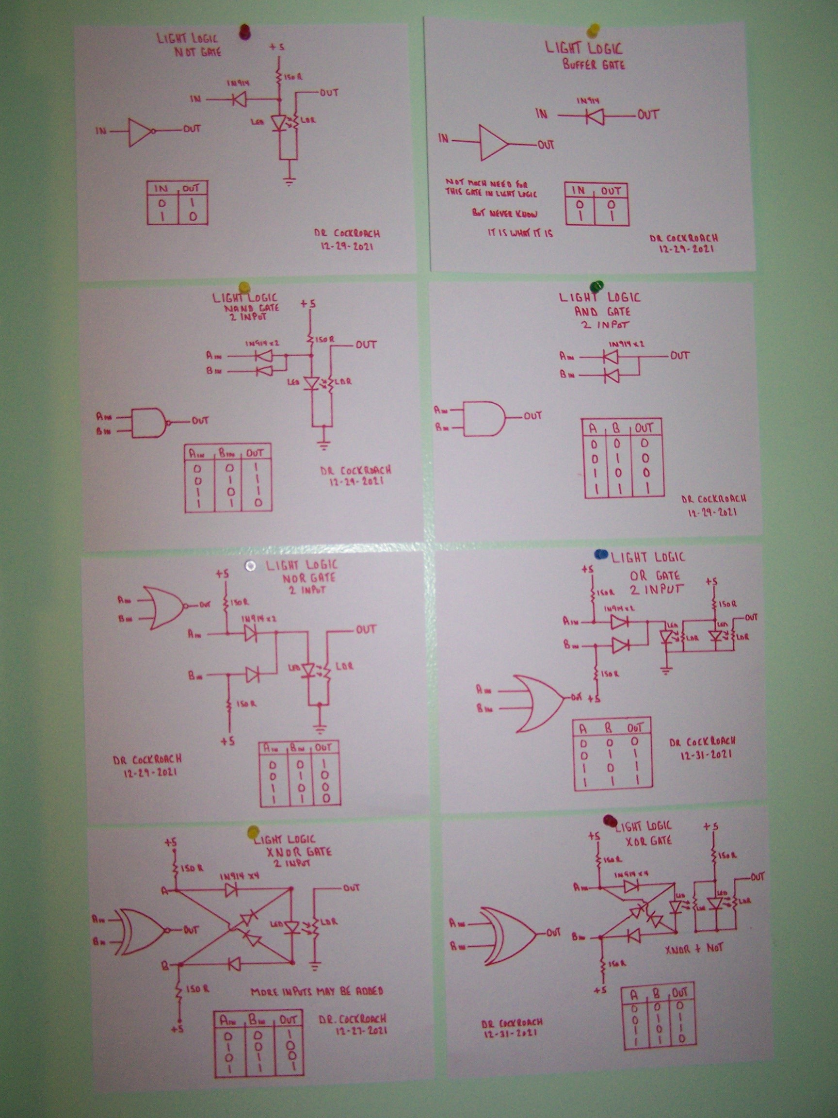
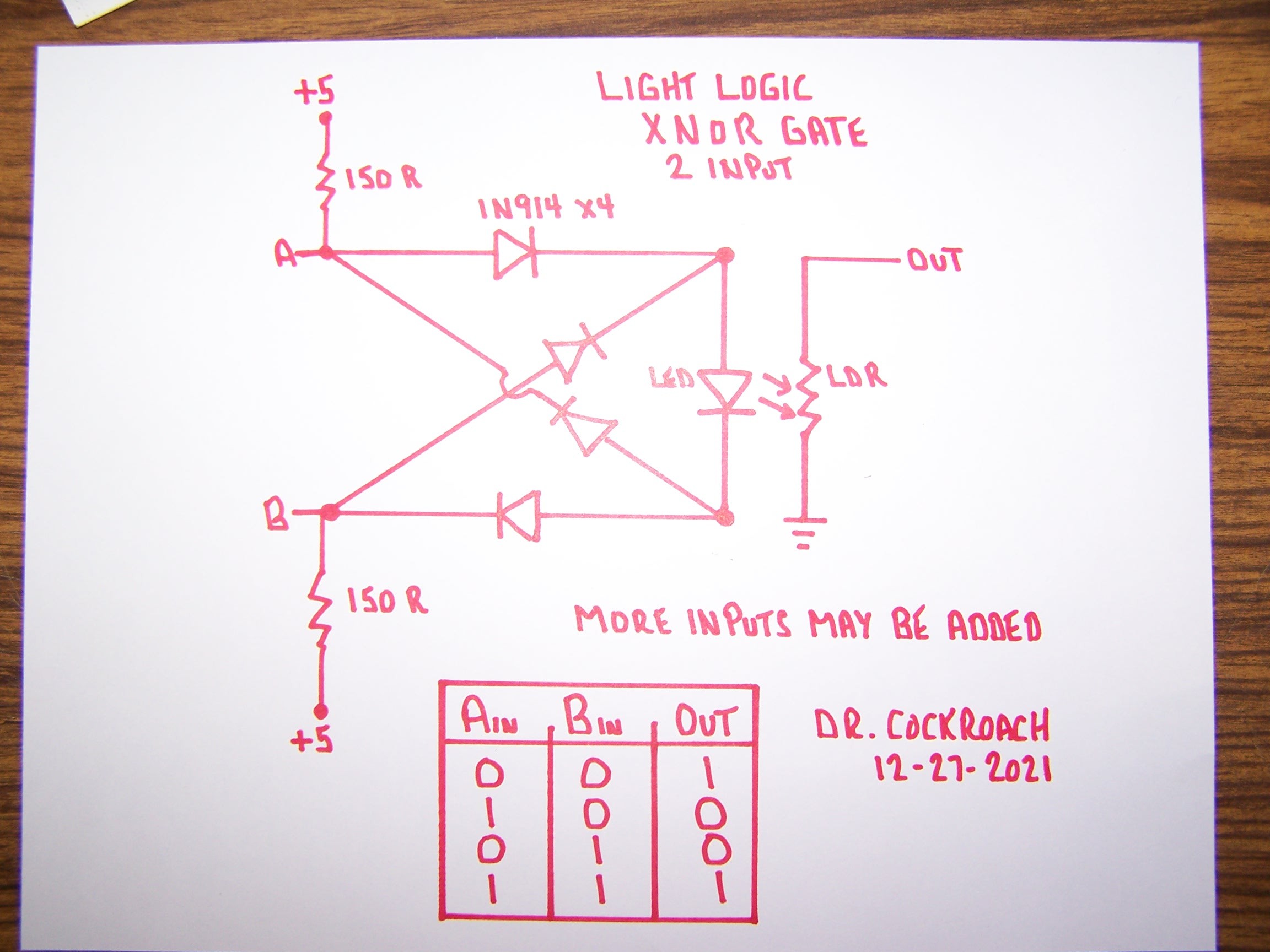
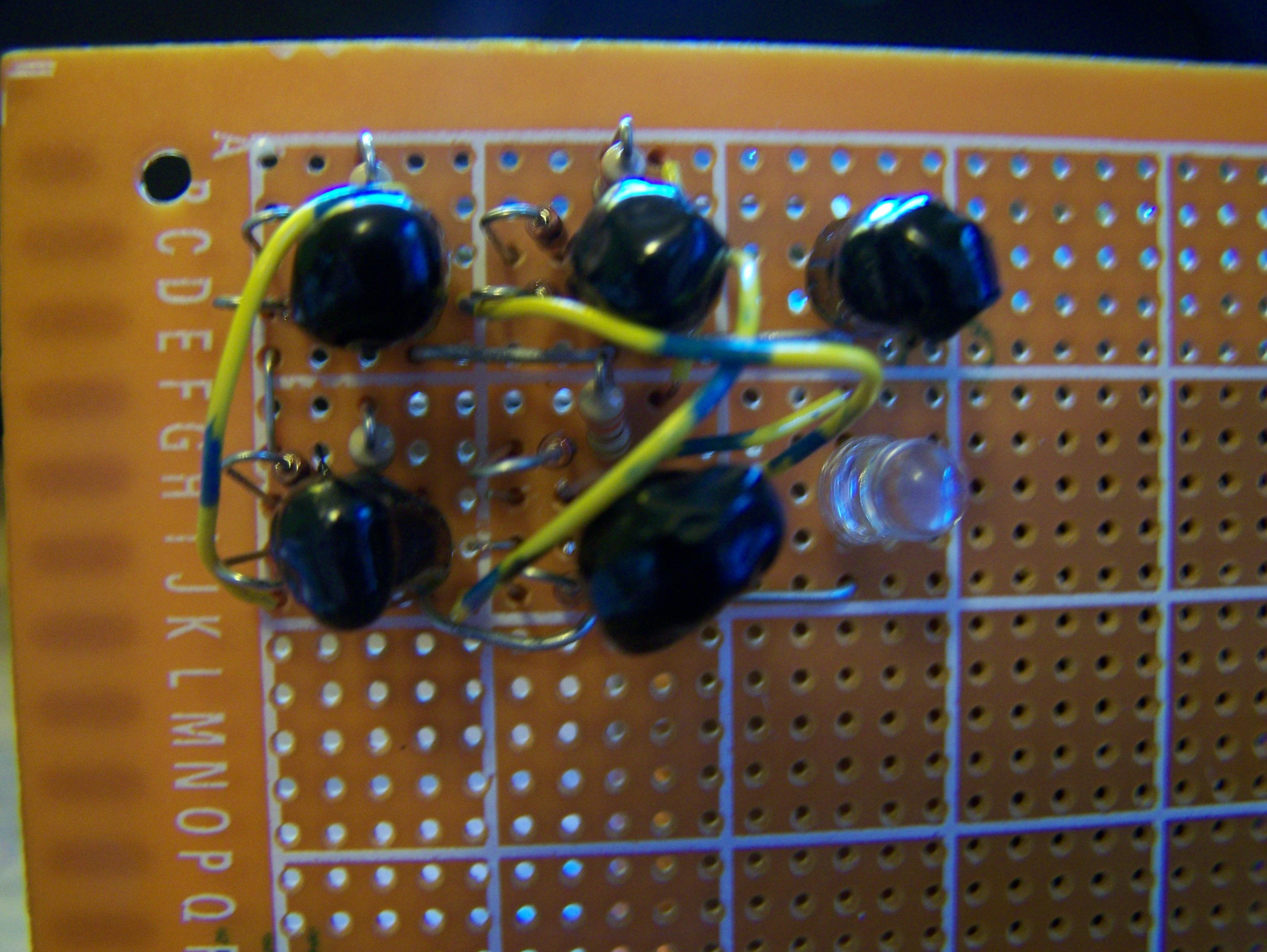
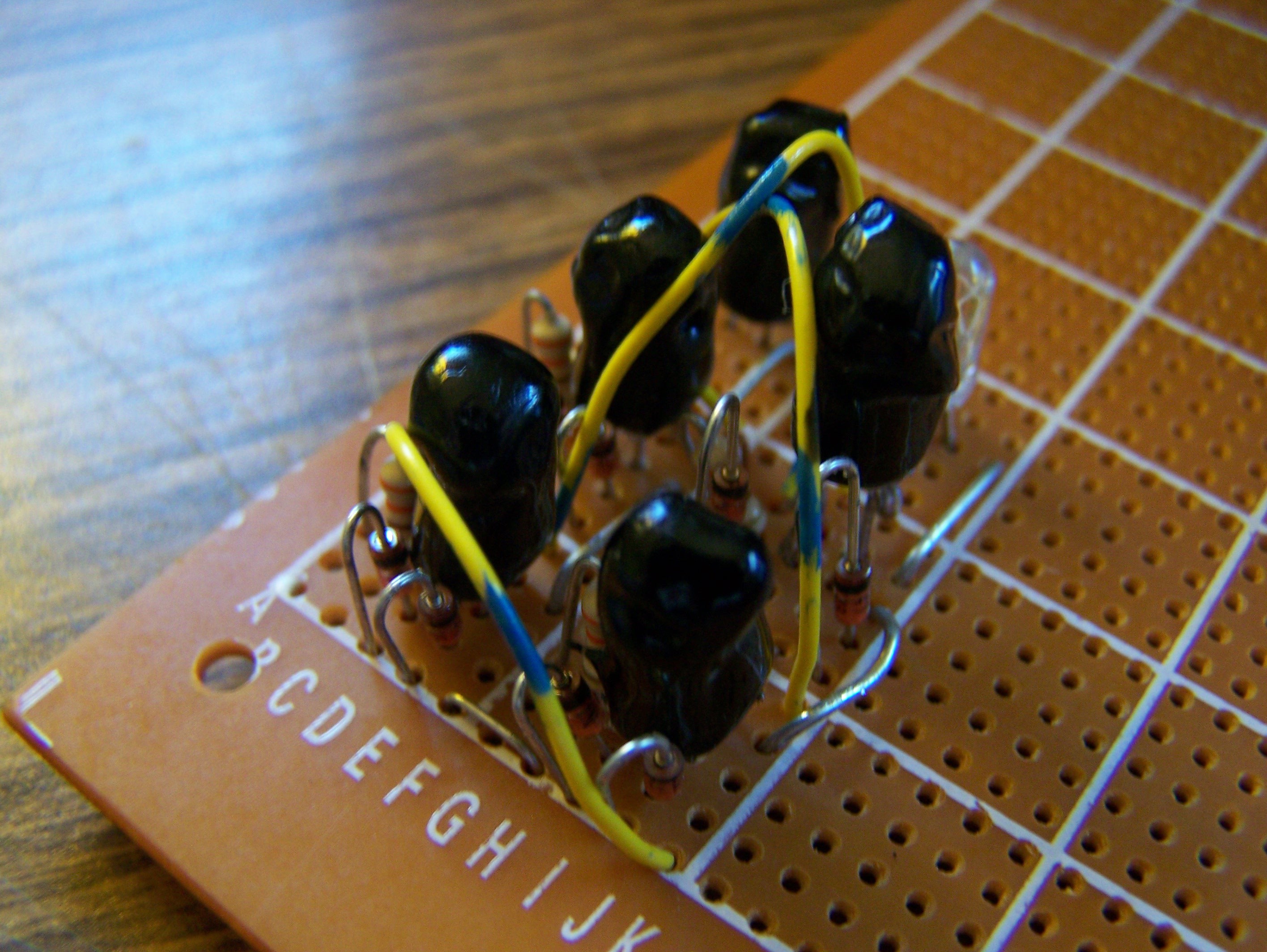
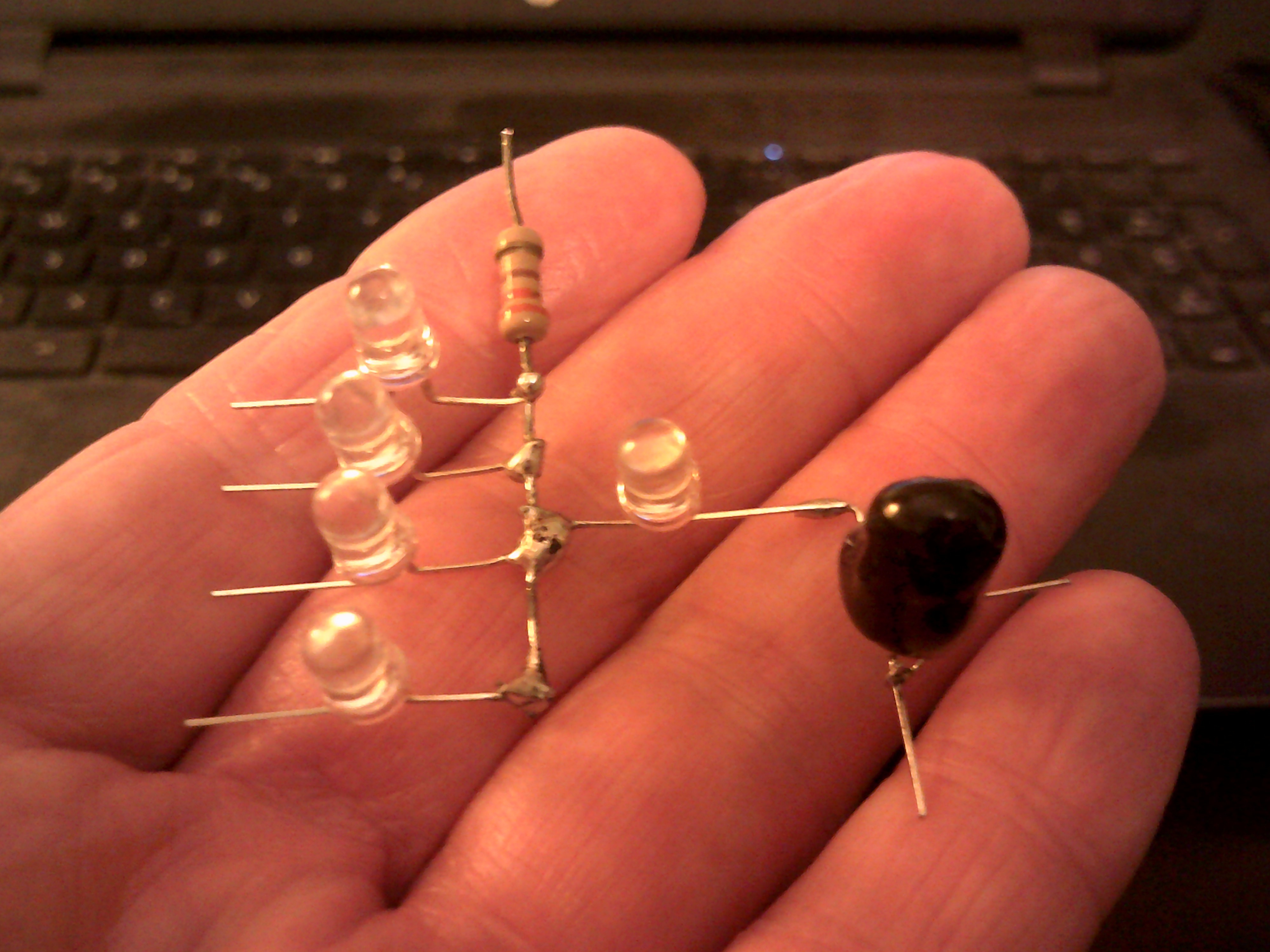
My interest in logic gates that did not make use of transistors started about two years ago. After about six months of hair pulling, yelling and cursing I was able to create the entire Boolean logic set using just diodes and resistors. Granted the key diode is a LED and the key resistor is a CdS Photo Resistor. Granted I do not expect anyone to think that this processor build will be fast or practical but is part of a grand "What If" idea I had and Light Logic was born. Now it is time to put those logic gates to work and see if a working processor can be constructed this way. So as to not confuse my senior moment prone brain, I will keep the logic gates down to just NAND and NOT except for the diode only AND gates used in the 4 to 16 line decoder on the Hex display module. The other Light Logic gates I have made will work but do not always play nice with each other and inverting logic just seems to work better for me.
LLTP - Light Logic Transistorless Processor
My attempt to create a CPU/MCU without transistors or relays
 Dr. Cockroach
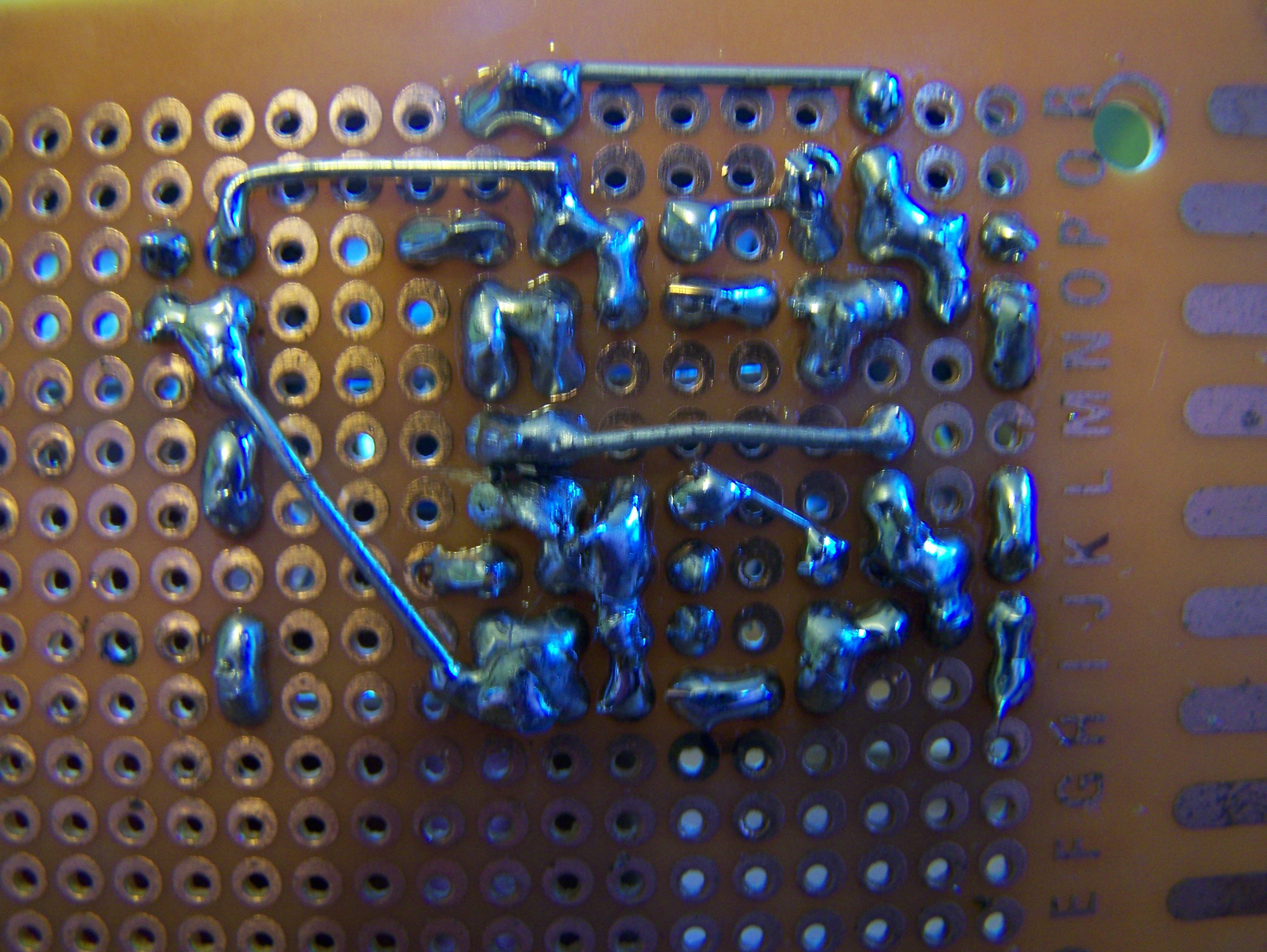
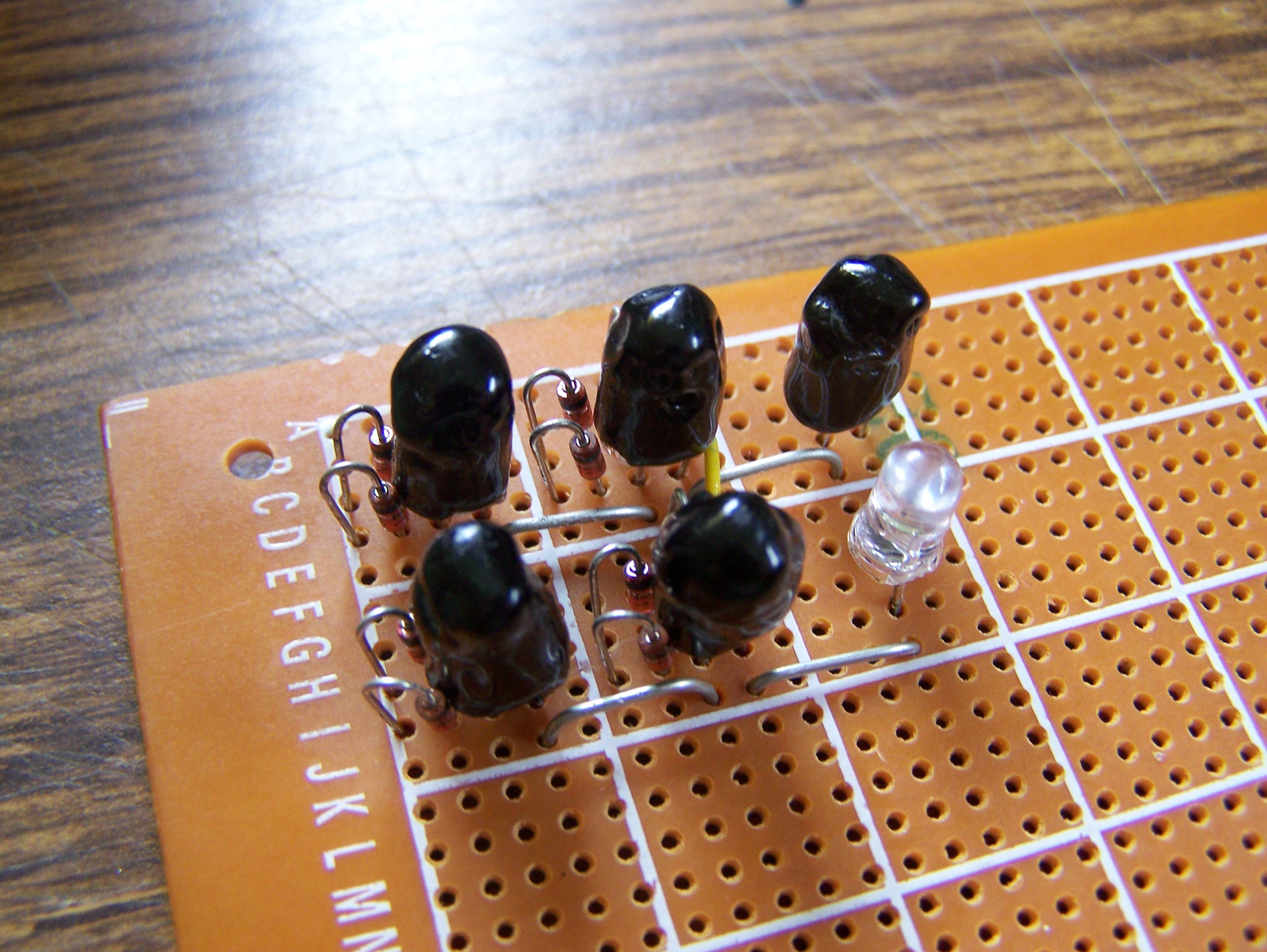
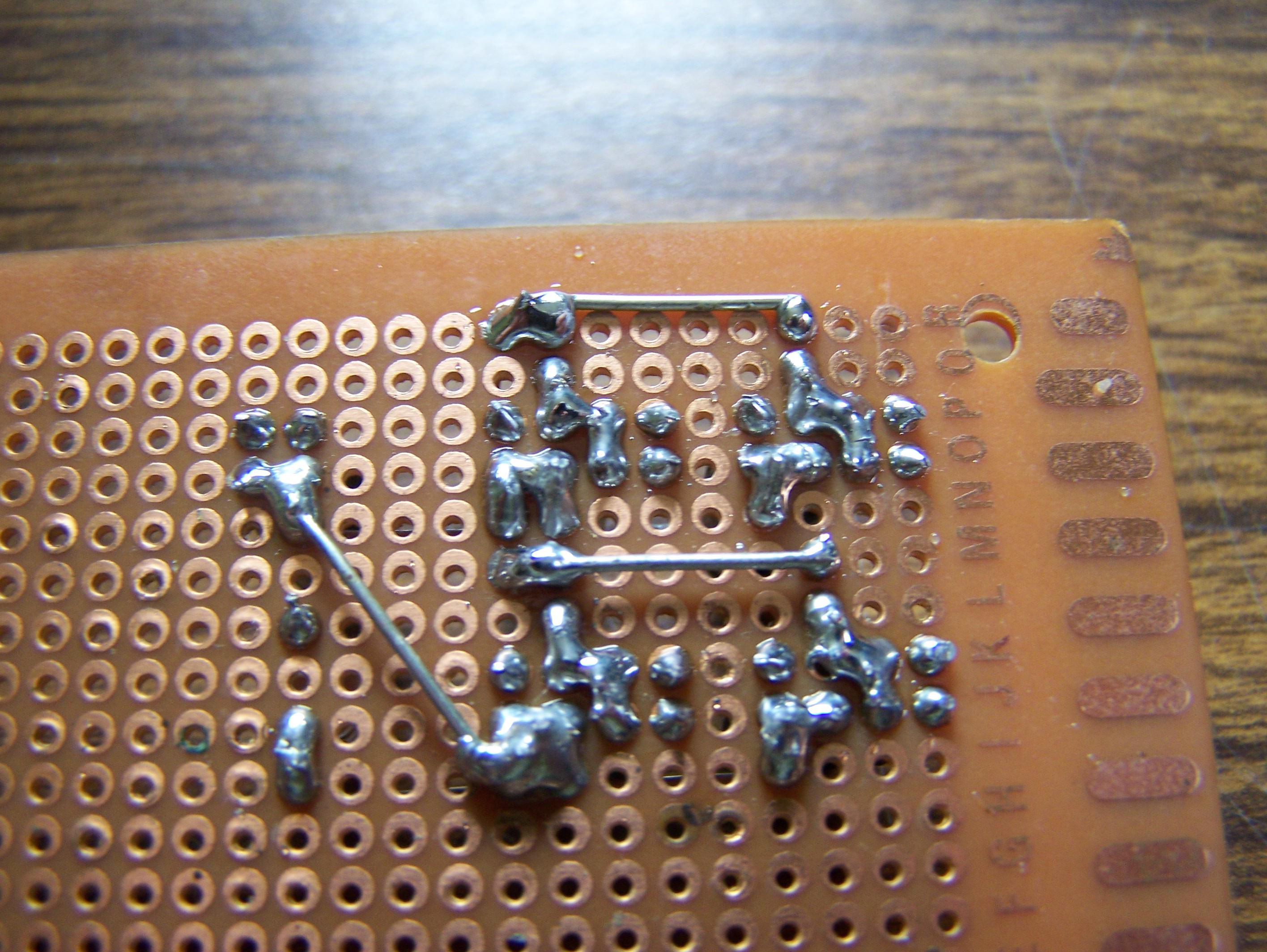
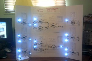
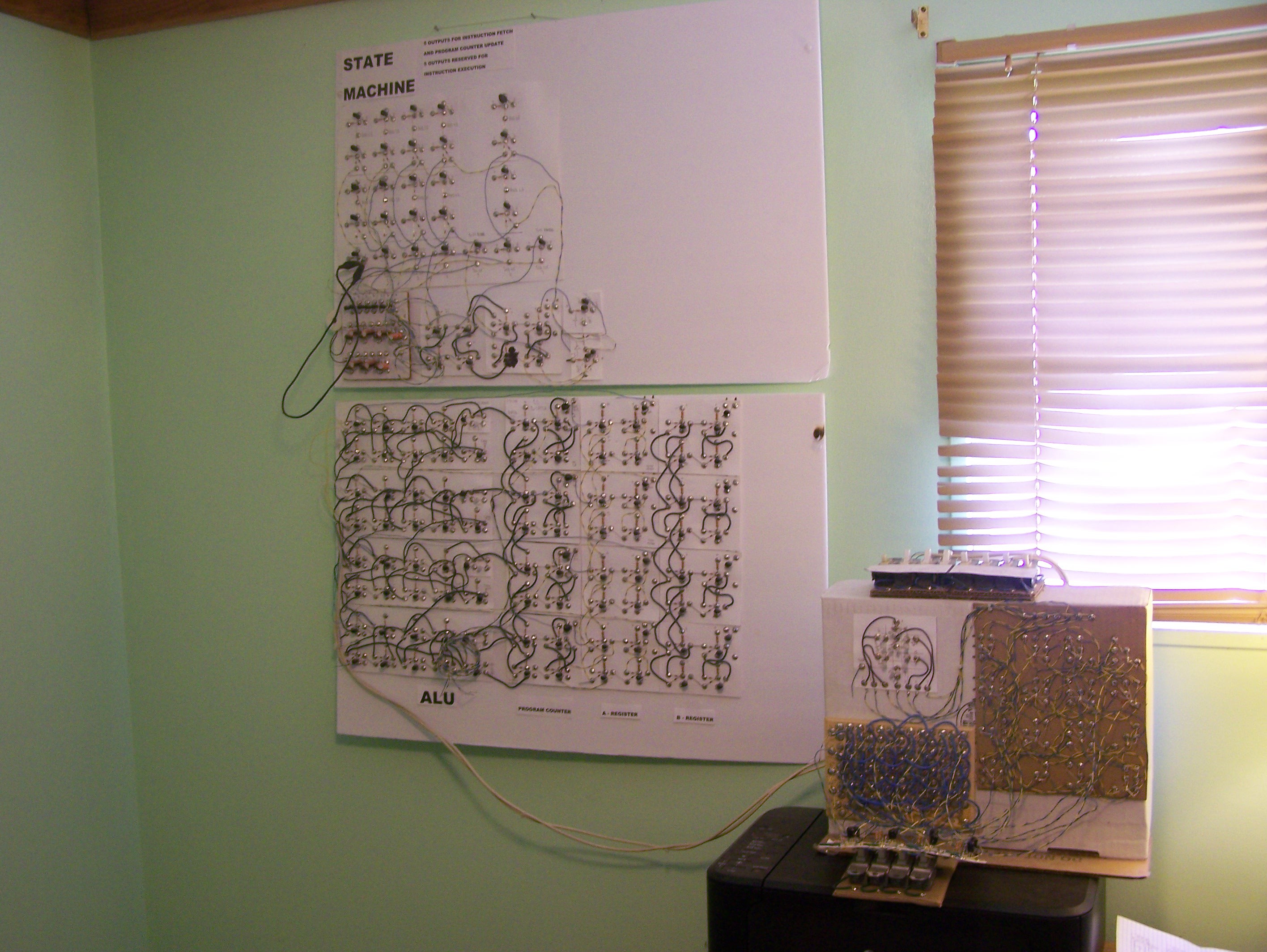 Finally getting the LLTP hung onto the lab wall like I wanted from the start of this project.


 will.stevens
You can reduce size by reducing the number of gates required. Any function can be implemented by two layers of gates. The first layer is AND (NAND), while the second layer is OR (NOR). PAL devices (ex 22V10) use this approach. To optimize the number of gates, Karnaugh maps can be used. Check out this URL: https://www.youtube.com/watch?v=RO5alU6PpSU