-
Brake actuator: Next try
08/10/2020 at 15:00 • 0 commentsMy last attempt to build an actuator for a mechanical brake went pretty wrong.
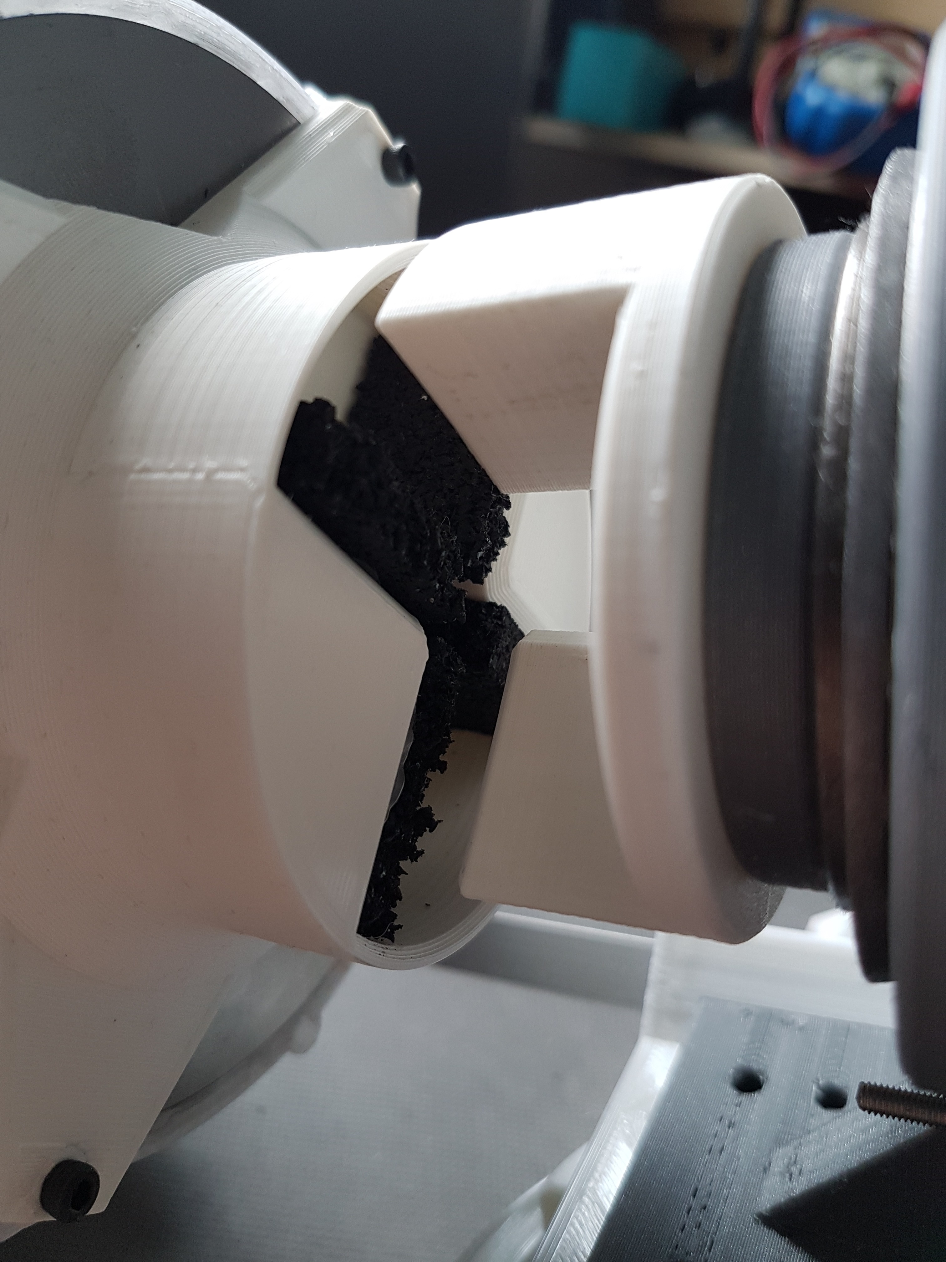
At that time I tried to press two bicycle brake blocks onto the rotor of the nerdiskerator with the help of two SG90 servos. As a result, the rotor should then slow down and ultimately come to a standstill.
Unfortunately the servos could not apply enough pressure. But see for yourself:
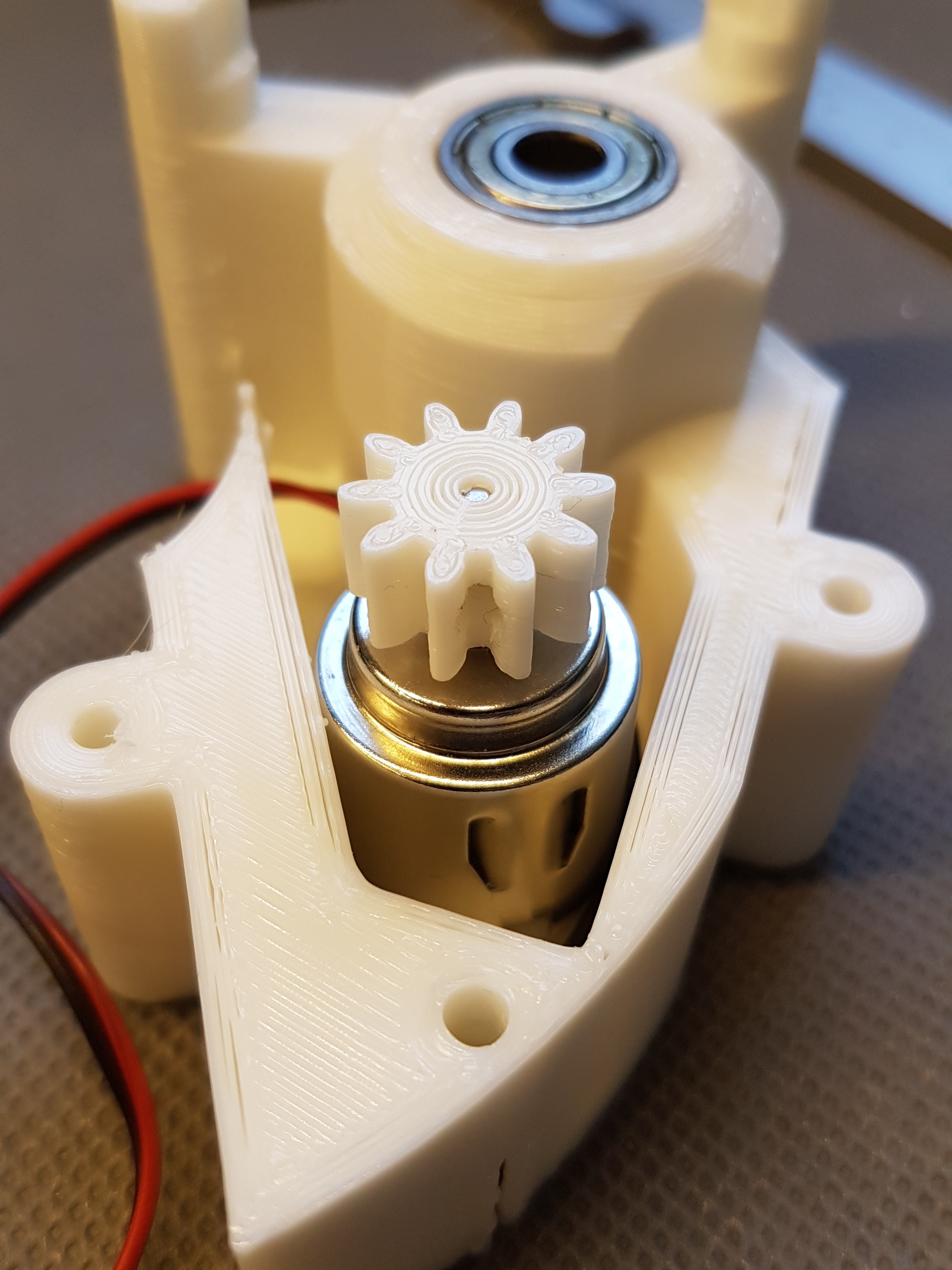
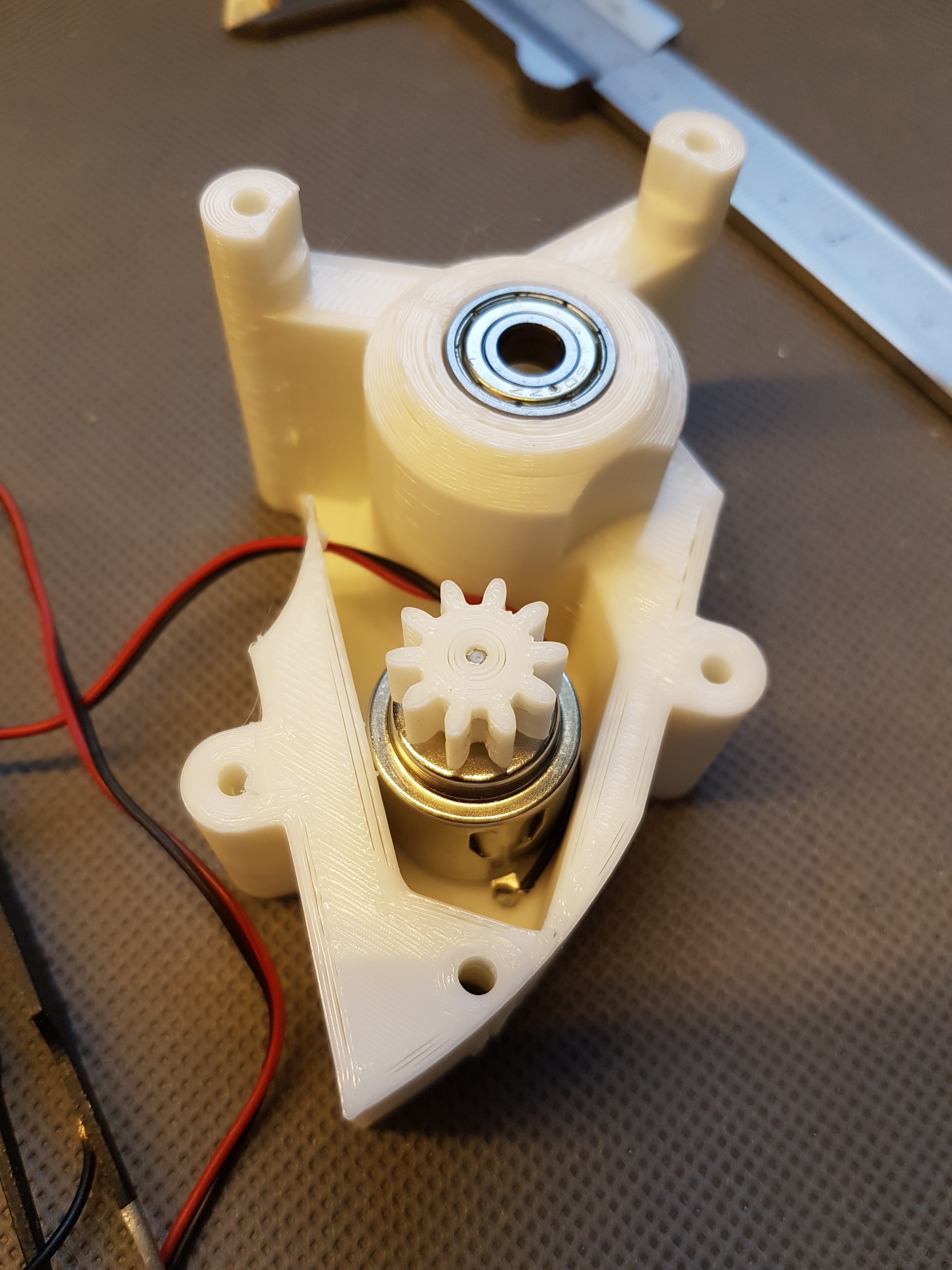
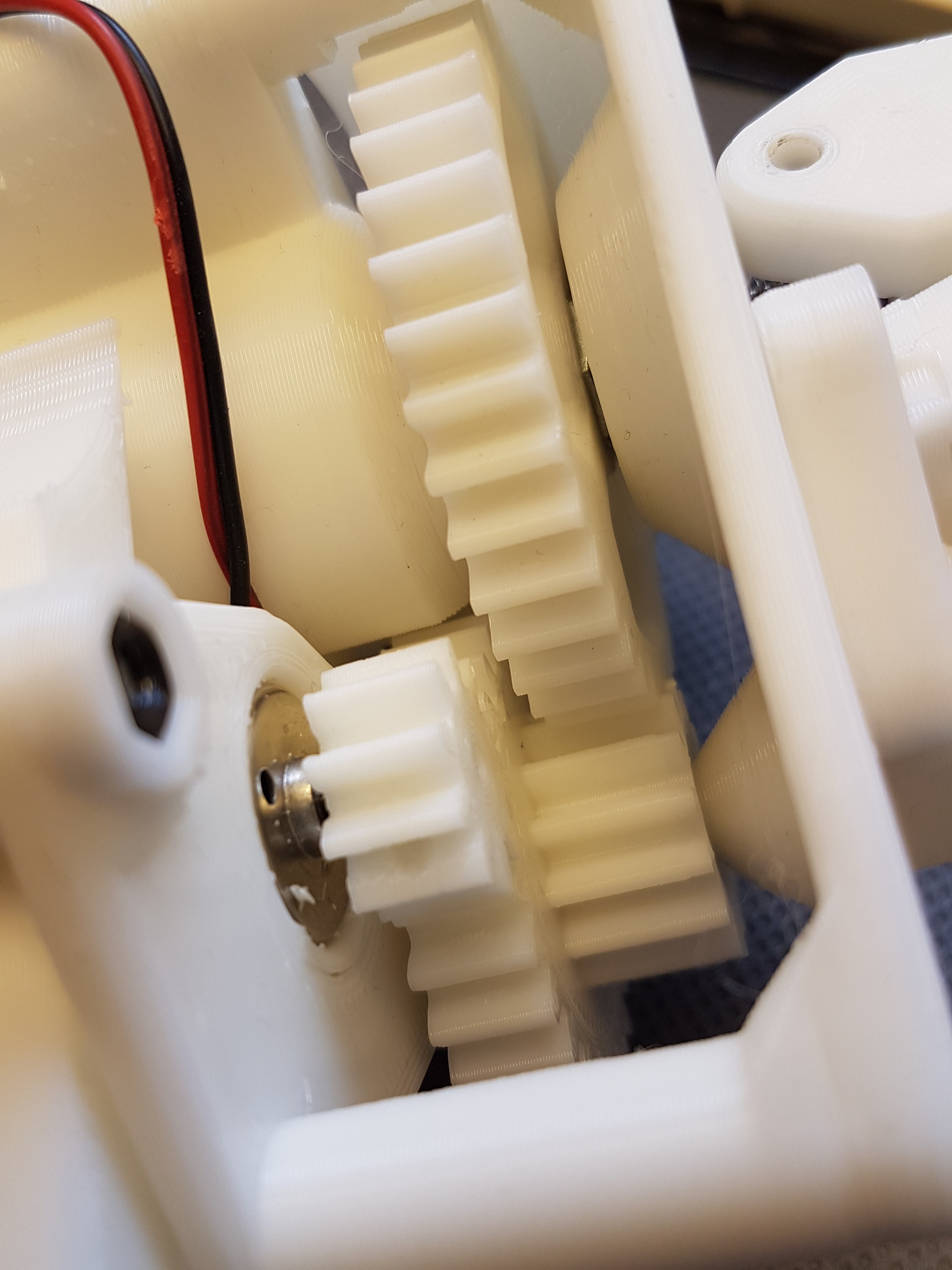
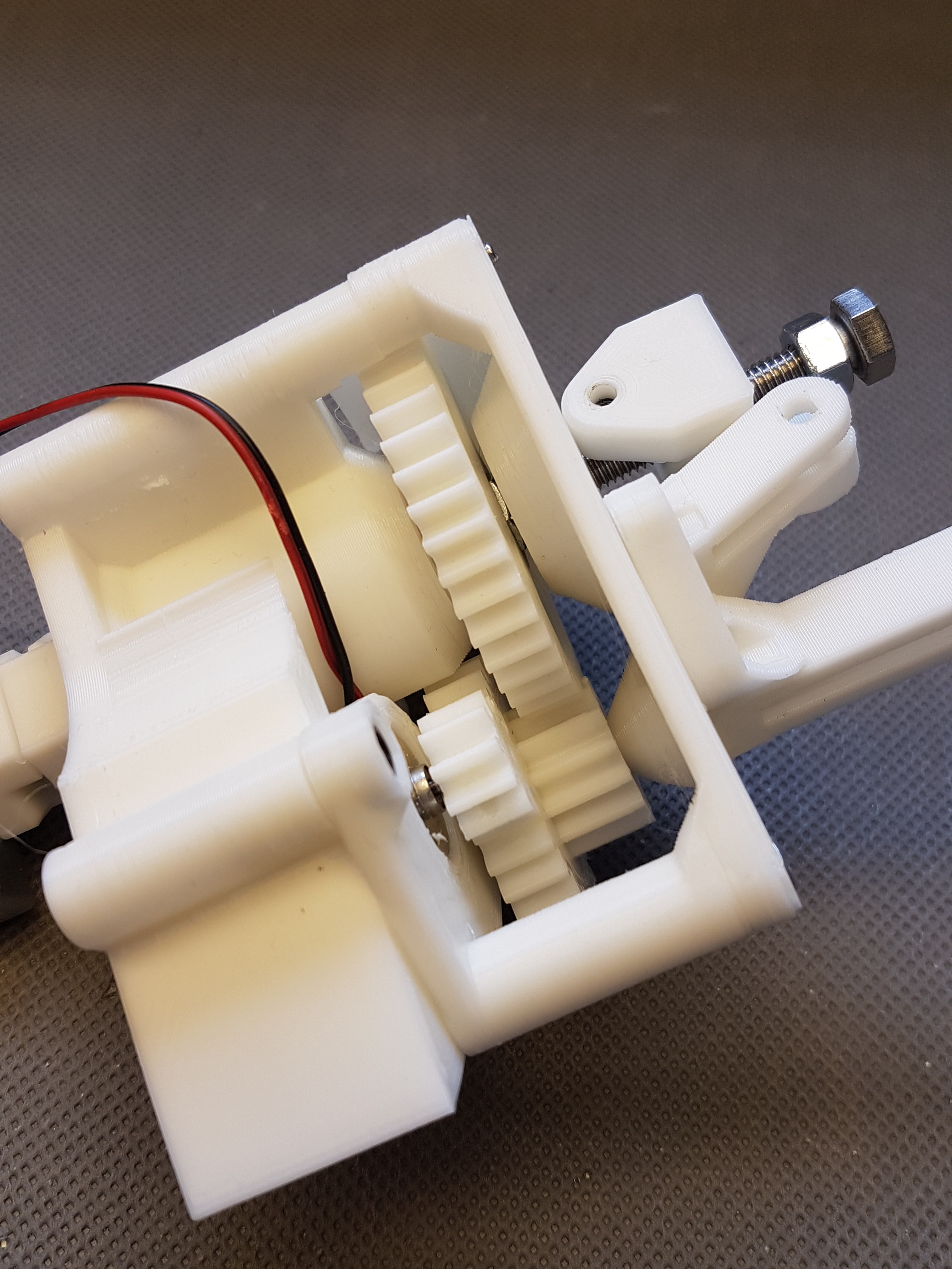
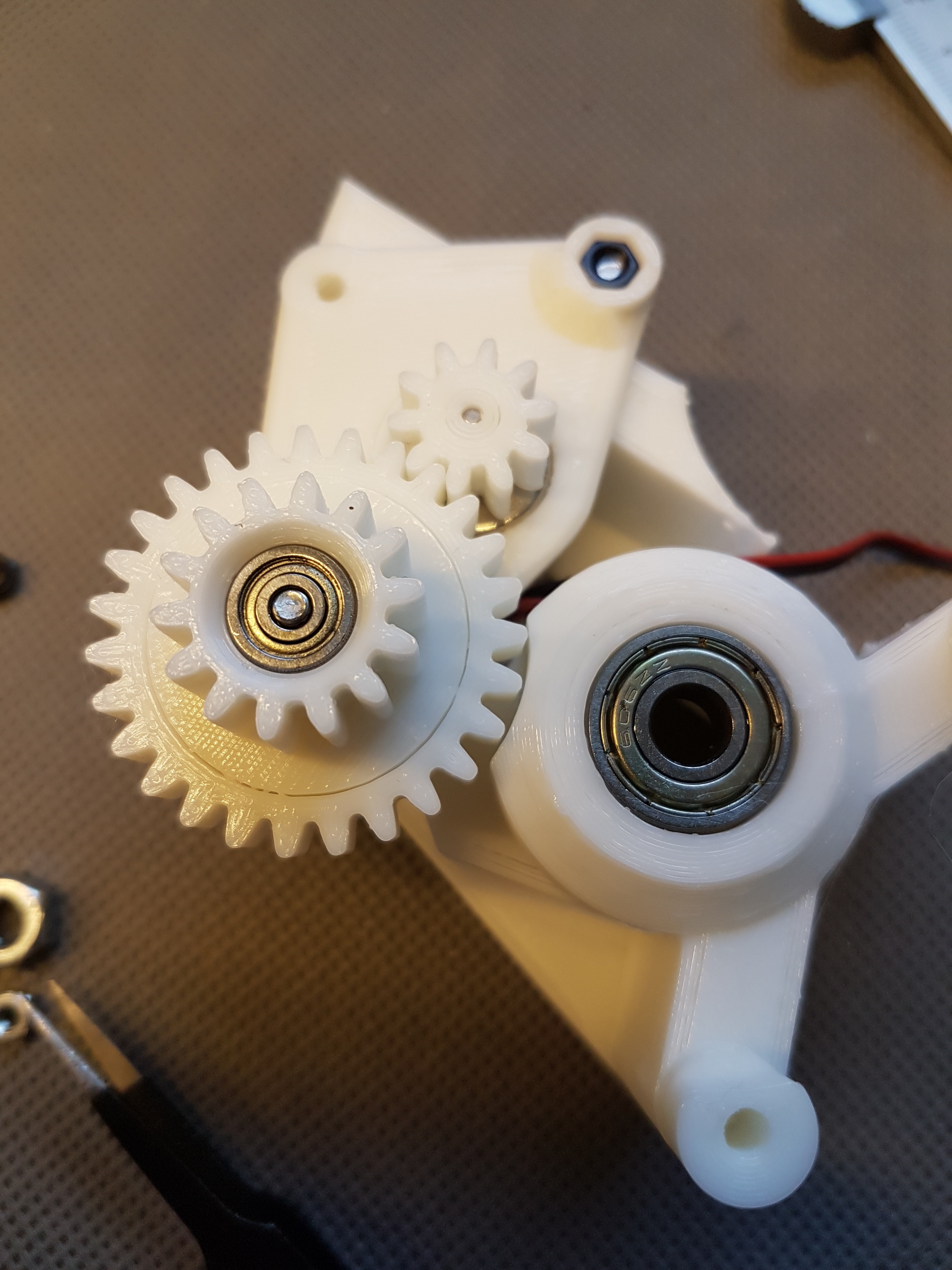
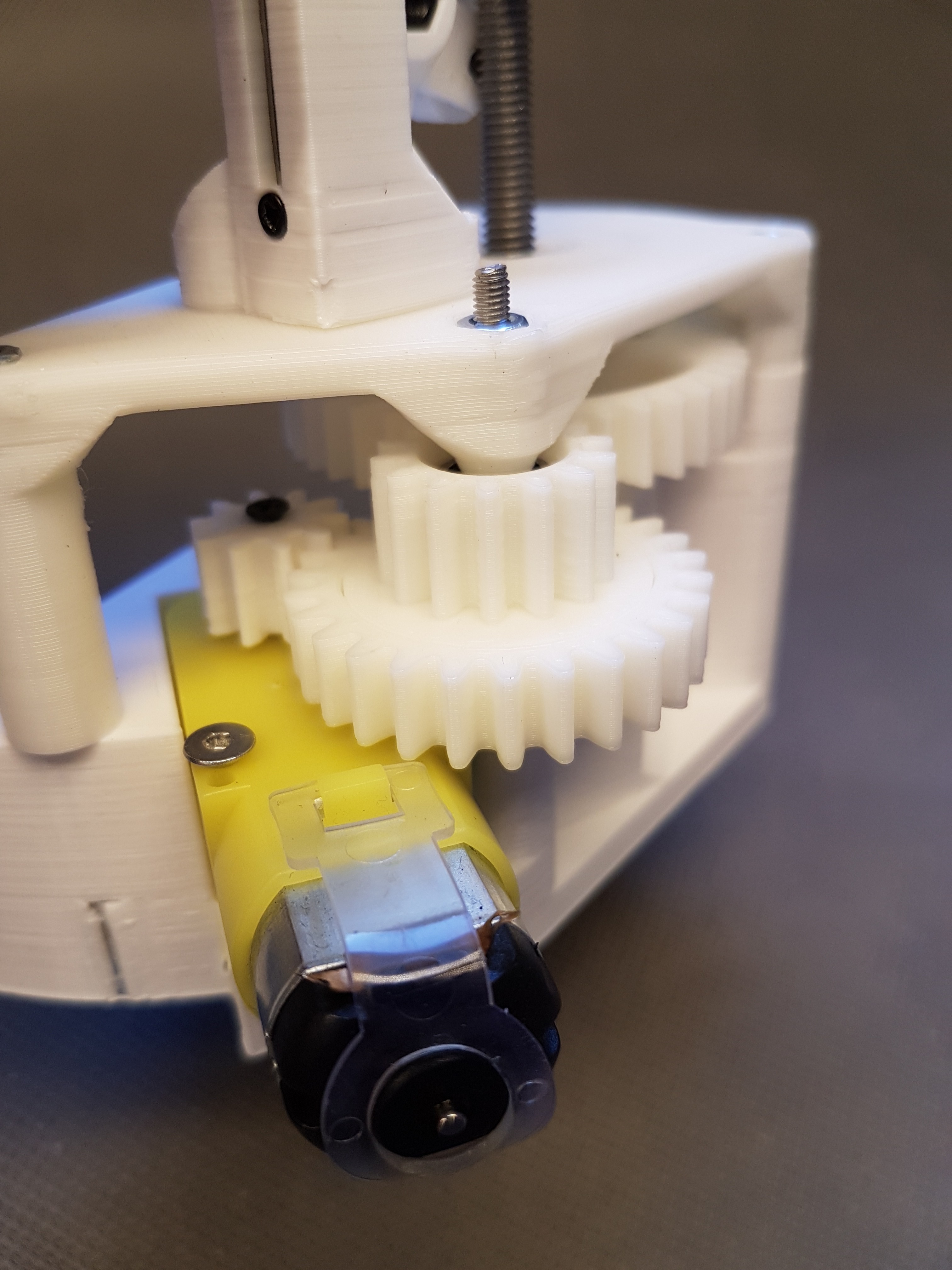
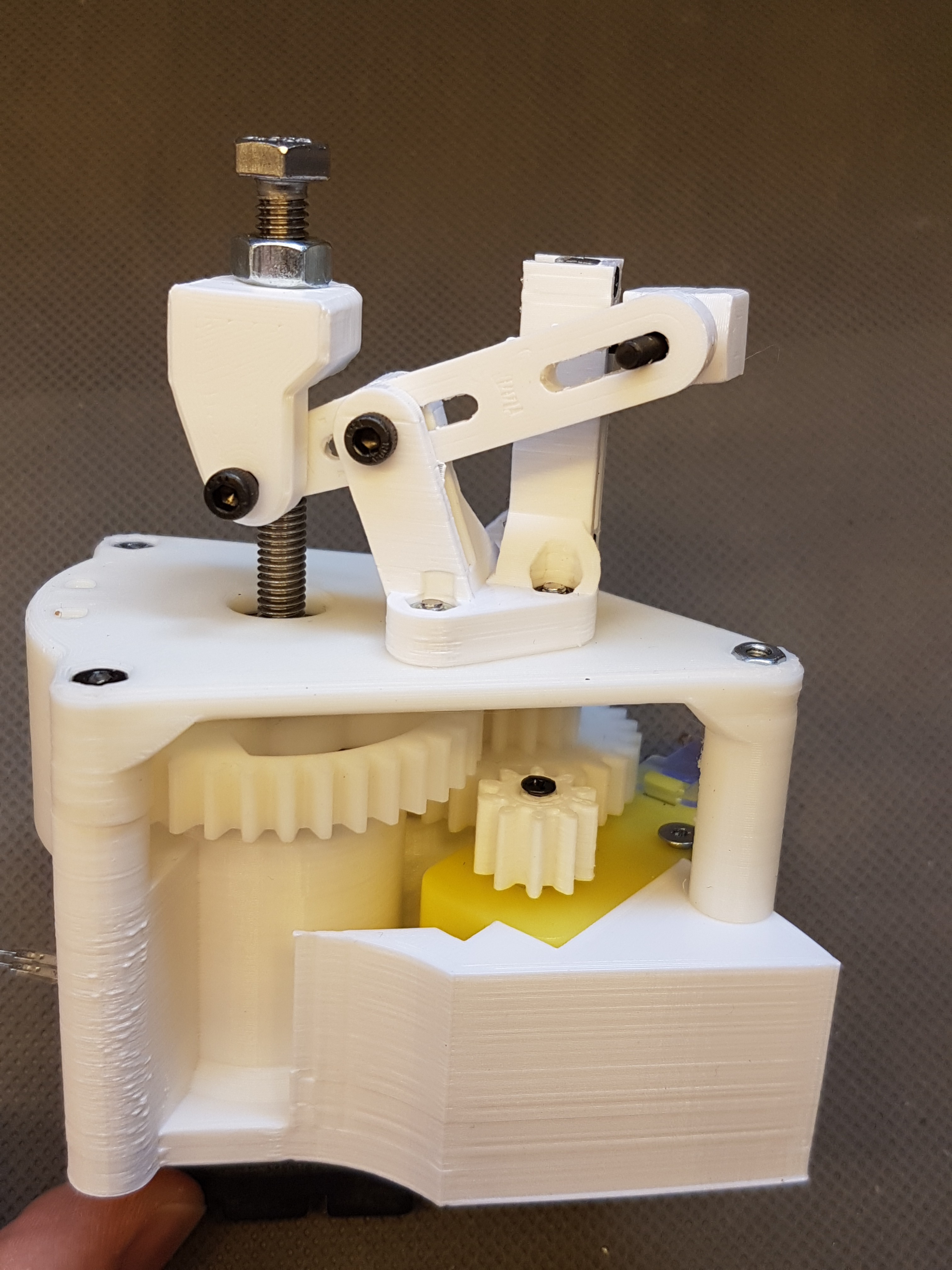
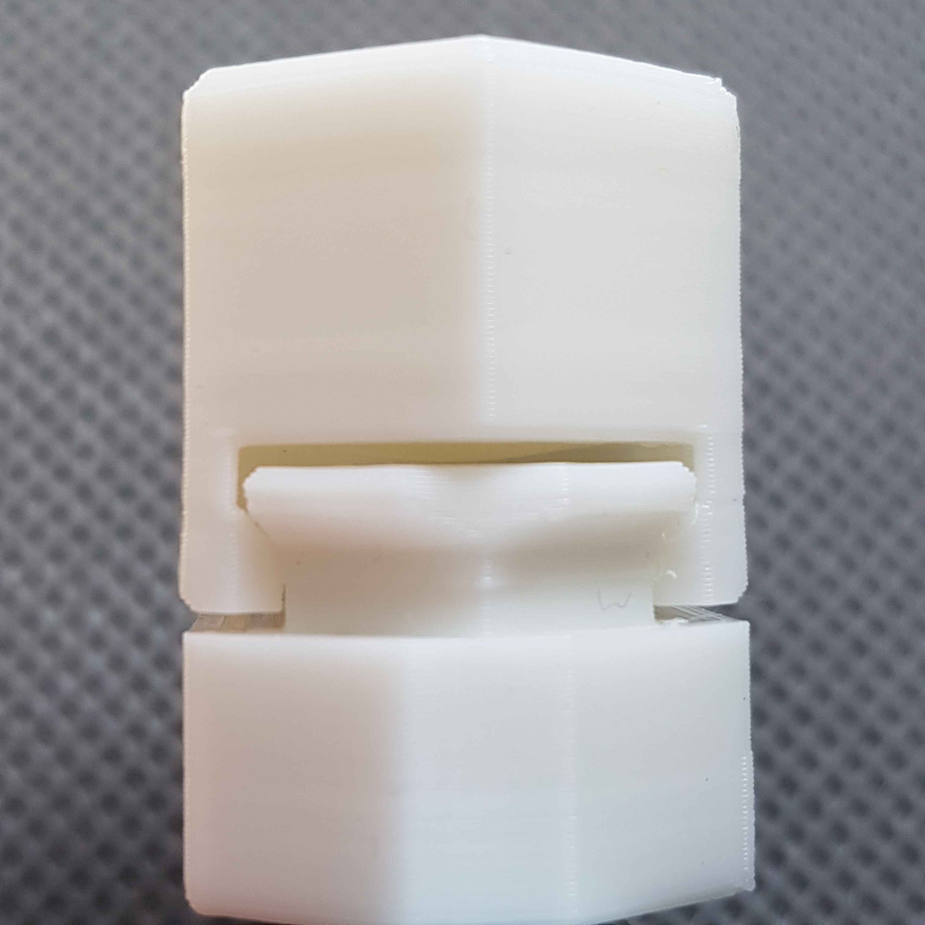
Next designIn order to be able to press the brake block onto the rotor with a little more pressure, I thought about a new design. This consists of two gear motors, of which each presses the brake cylinder onto the rotor of the generator via a small reduction-gear.
At the beginning I experimented with the same (too weak) dc motor that I had already used for the pitch actuator. Unfortunately this was too weak for the brake actuator, which is why I later switched to the same geared motors that I use for the latest draft of the pitch actuator.
Design using (to weak) dc motor
![]()
![]()
![]()
![]()
![]()
![]()
Design using a geared motor
A video of the running prototype is visible here: https://www.instagram.com/p/CDGdRvbKCRp/
Some pictures here:
![]()
![]()
So that the position of the brake cylinder can always be absolutely determined, a sliding resistor is coupled to the brake cylinder via a lever reduction on the back. So 5 to 7mm movement of the brake cylinder are "scaled up" to the 20mm of the sliding resistance. So you can take advantage of the whole "resolution" of the slide-resistor.
More information is also available in this post: https://www.instagram.com/p/CDTp1OXKpsS/
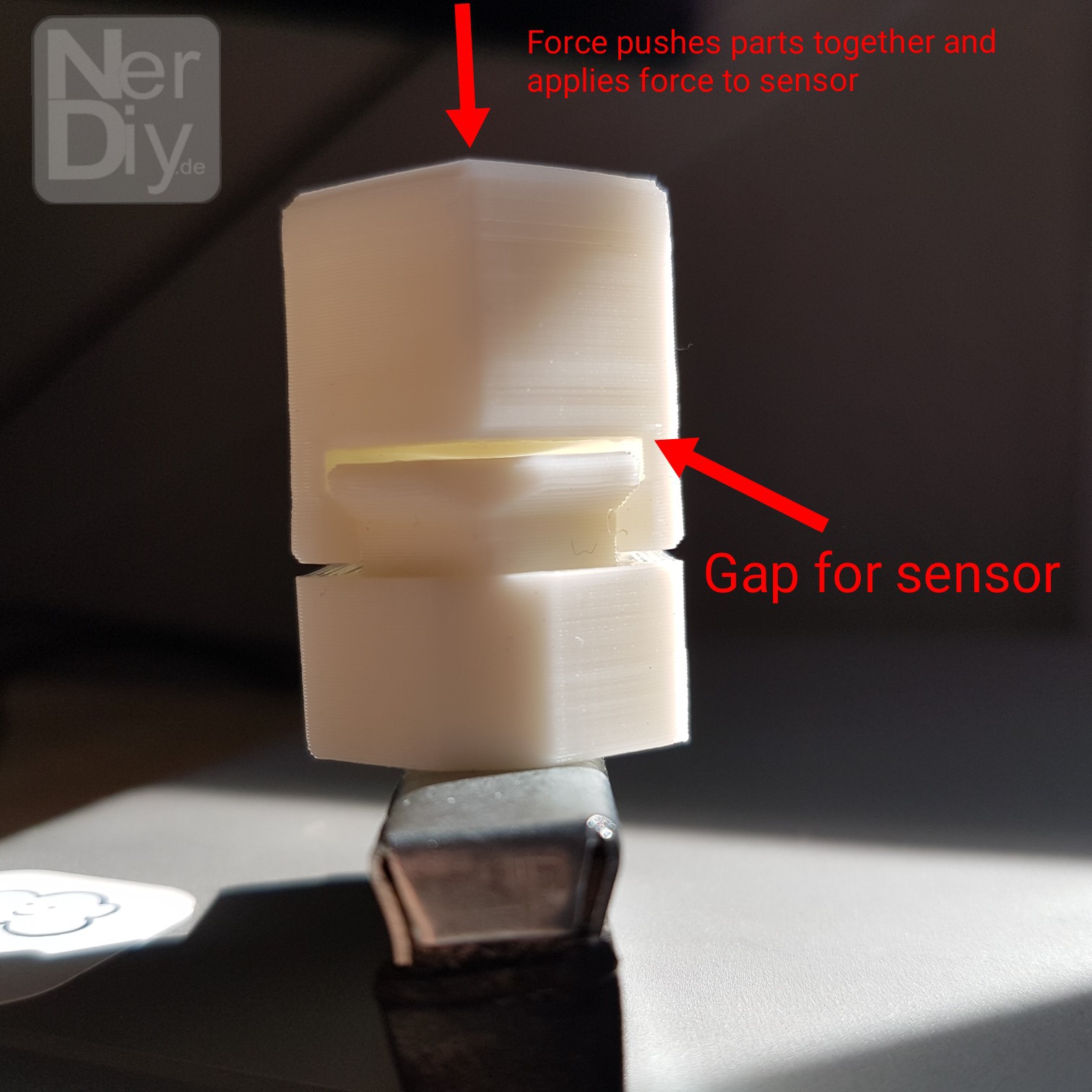
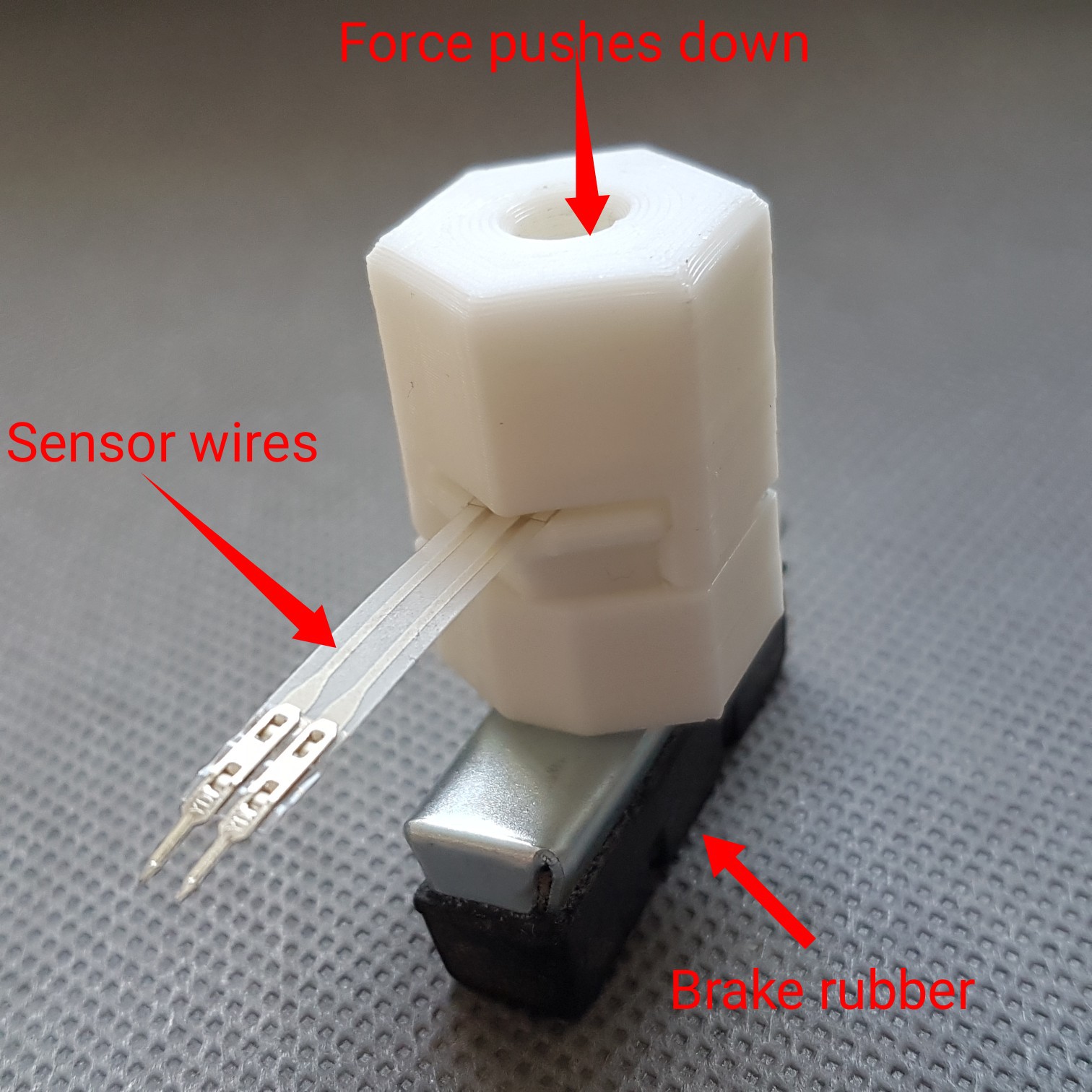
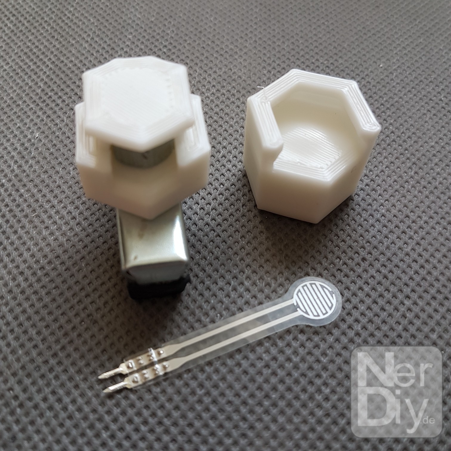
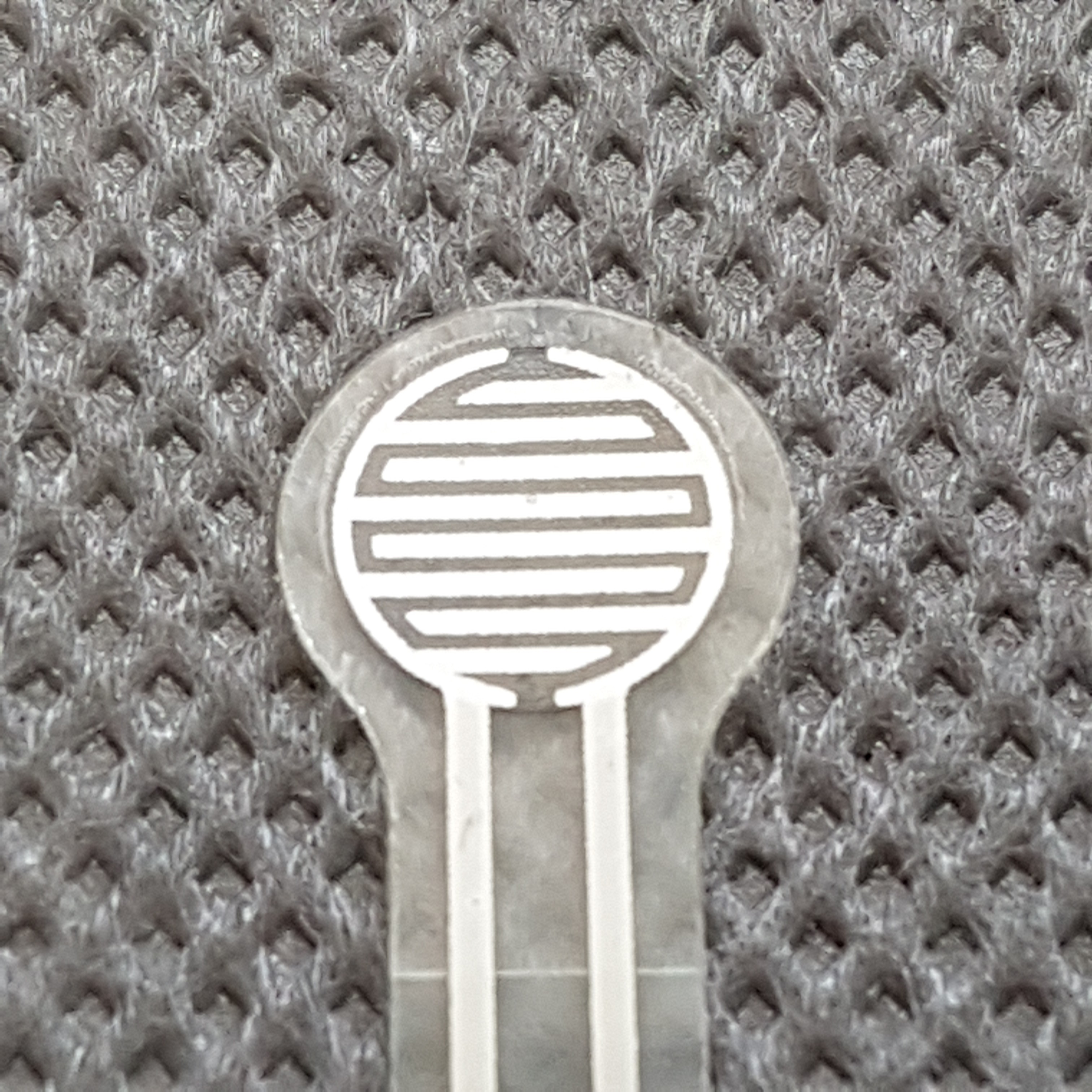
I also installed a force sensor in the brake cylinder itself. This should measure the force with which the brake cylinder is pressed onto the rotor. You can read a few more details about this here: https://www.instagram.com/p/CDl4wGYKugw/
Some more pictures about that:
![]()
![]()
![]()
![]()
![]()
Last but not least, I plan to use an i2c motor driver to control the dc motors. Thanks to a shunt resistor, it can also measure the motor load. This allows the controller to recognize any unusual load and switch it off.
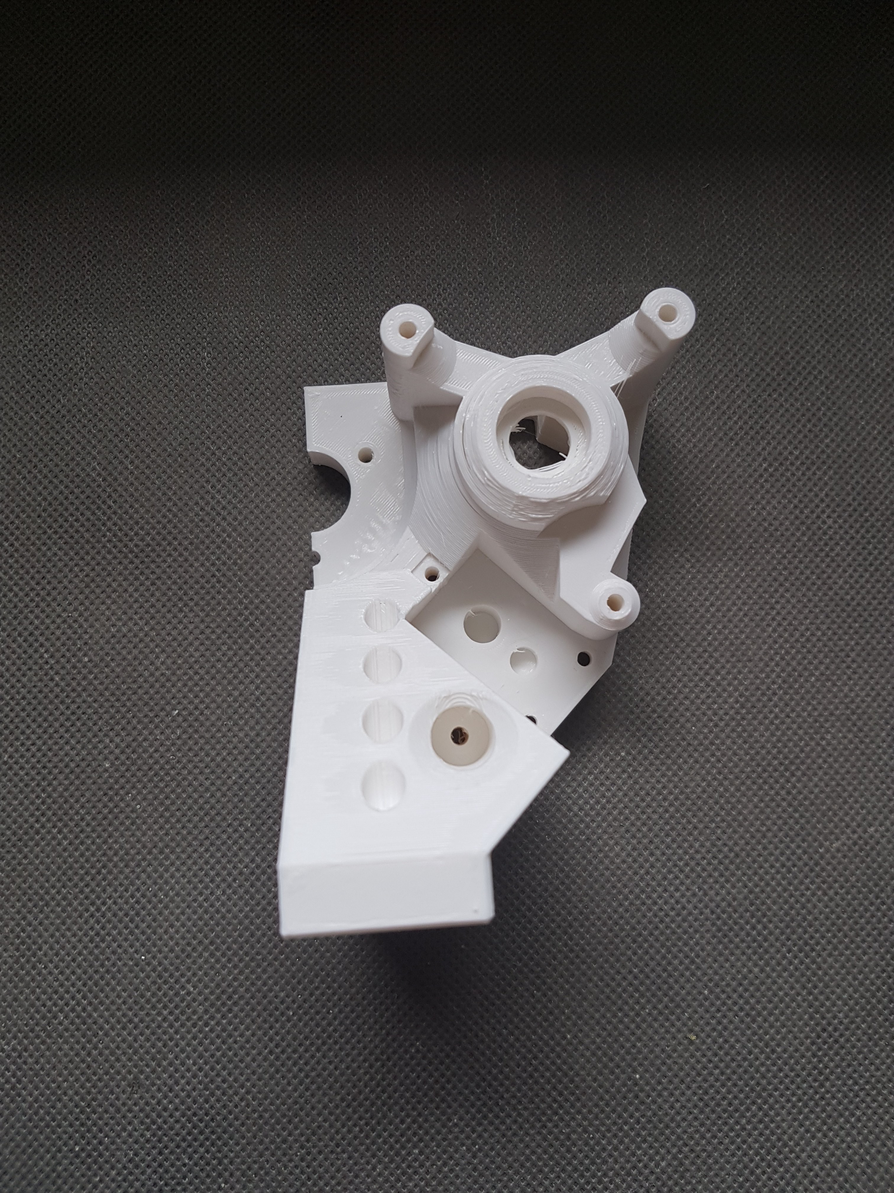
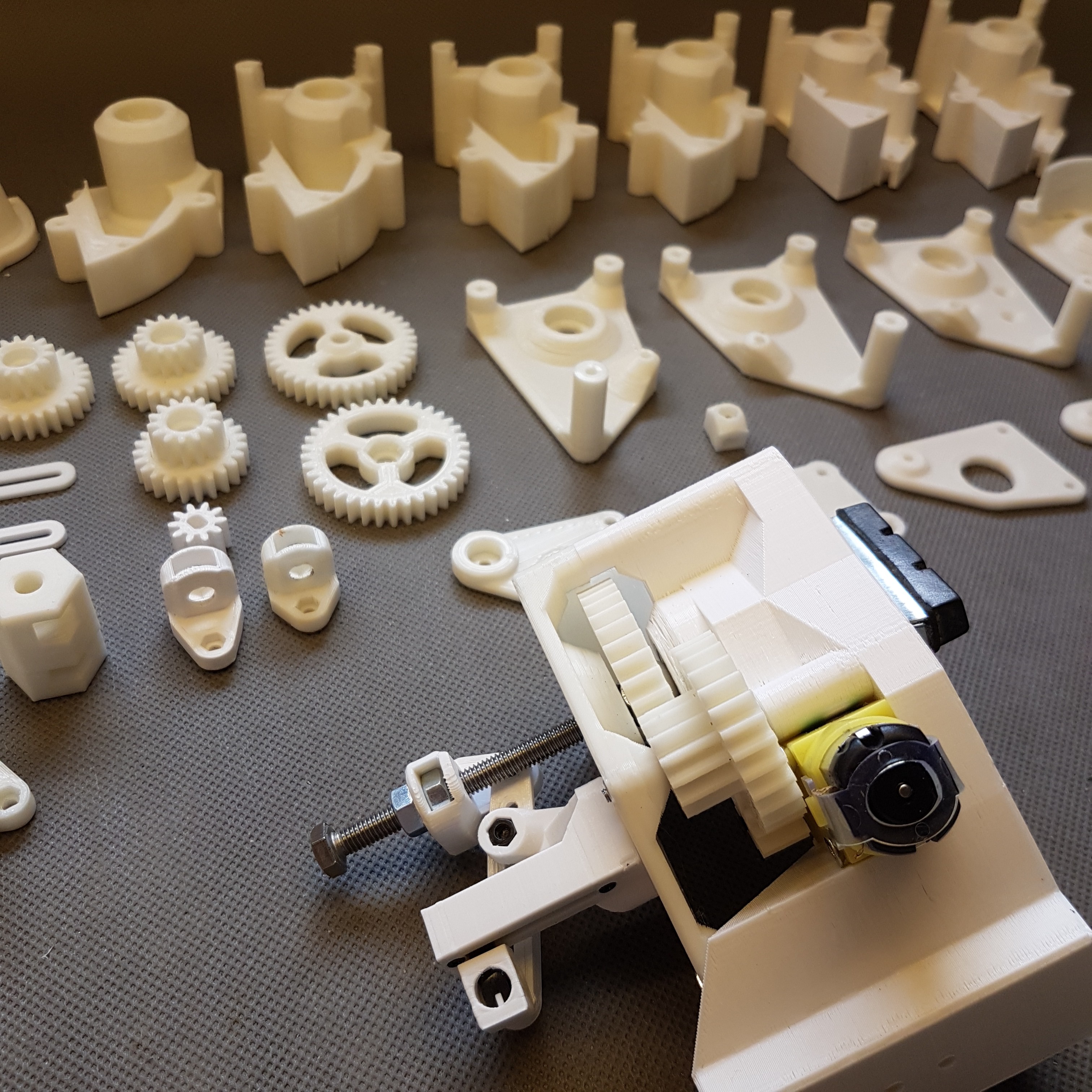
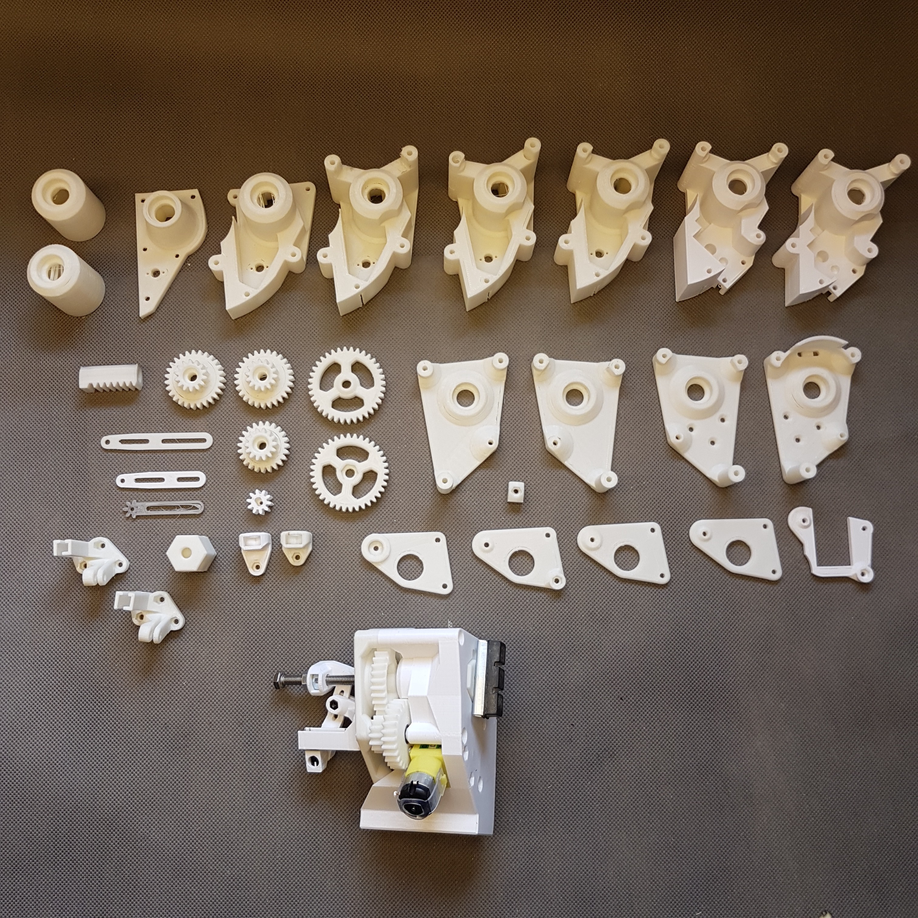
After all this itteration i had created a huge collection of different failed parts that were iterated part by part.
A small overview of this parts:
![]()
![]()
Finaly I reached the actual state:
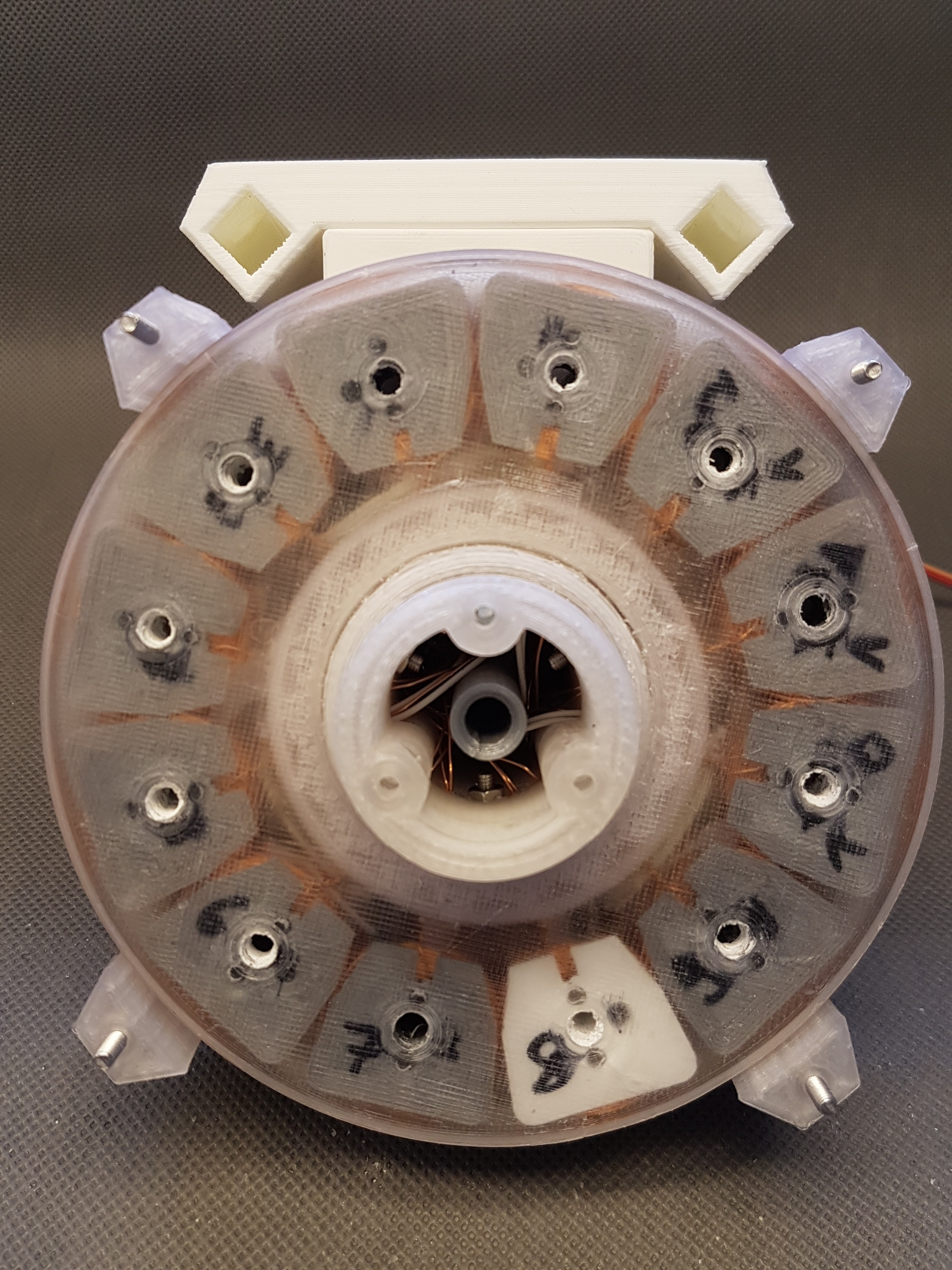
Two brake actuators integrated in the mount of the nerdiskerator:
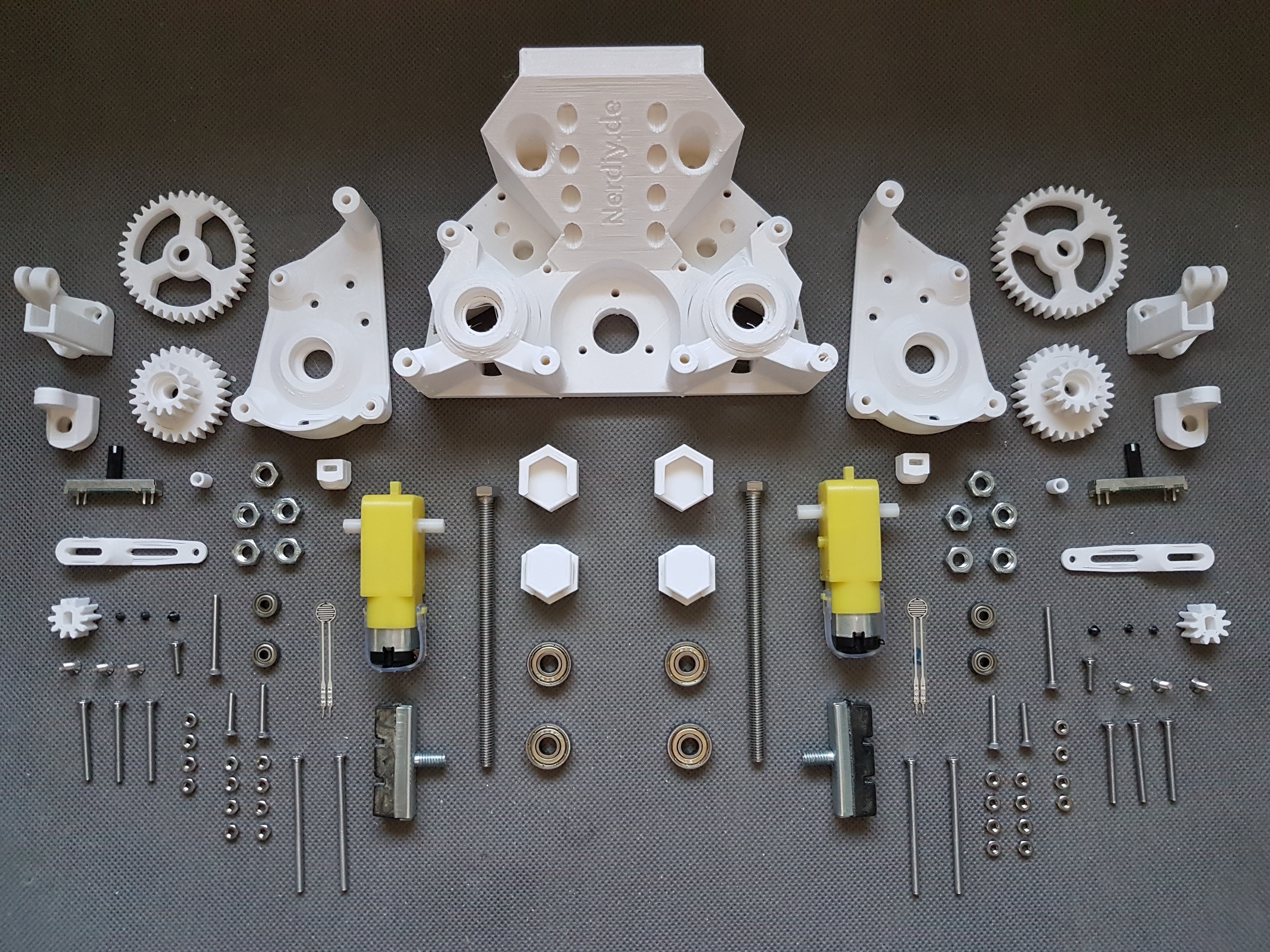
A quick overview about the used parts:
![]()
Took me a while to finish this part but now I'm pretty happy with it. :)
-
Start of development of the "Nerdiskerator-controller"
07/20/2020 at 13:36 • 0 commentsYesterday I (finally) started developing the controller for the Nerdiskerator. This should monitor the various sensor values and intervene if necessary in a regulatory manner or even deactivate WinDIY. Of course, I noticed a few things on my previous sensor-/actuator list that I would like to change.
Here I just wanted to describe what and why I changed it :- Endstops for brake cylinder: I will not implement this endstops because i think they are not really needed. At the brake cylinders I'm actually using three kind of sensors. One is reading the absolute position of the brake cylinder via a sliding resistor, the next oone helps to read the force that is applied by the brake cylinder onto the disk of the disk generator. This actually already is some kind of endstop because it signals the blocking situation (that we also need for braking properly). The last sensor is the current sensor of the supply voltage for the motor that drives the brake cylinder. If this goes up its easy to indicate if the brake is blocked. In combination with the other sensors it is then easy to determine if the brake cylinder is in the front or back position or that it is blocked in the range between these points.
- Stepper motors are exchanged for dc motors: This was actually needed because the planned stepper motors were way to slow. See here for more details: https://hackaday.io/project/172328/log/180247-the-pitch-actuator-in-action
So much for the things I want to change or remove. Here are the things I would like to add:
- Standby usb power: This will be a 5V/3A USB Output that is driven by the integrated buffer batteries. I just integrated this for later usecases to (for example) power a raspbrryPi by this setup
- Temperature sensors to read the pcb temperature: Recently found the "MCP9808" an I2C controlled temperature sensor that could be helpfull to read temperatures on some specific areas on the PCB
- BME280, Brightness sensor and UV sensor: We are already collecting a lot of data here so some additional climate data cannot hurt either. I think tis is mostly usefull if you also would monitor some environmental data, but of course its not needed to make the Nerdiskerator/WinDIY work.
- External magnetometer: I will add a place for an HMC5883L on the PCB and also for an external one. The external one is for the case that the sensor does not work on the pcb(so close to the elctronics/magnets/generator)
- Button connection on the PCB and externally as WakeUp Source: Some Buttons will be emplemented: For example as emergency stop, wakeUp source ( I plan to let the controller go to sleep in case there is no wind/the generator is not driven)
- Up to 3x Lipo 18650 cells: Since I'm planning to add a USB-Port to the PCB i think some extra power is not bad. Will keep this feature optional, so that you could also use one or two cells only.
- Buzzer: For audio-notification in case something is wrong. Not really sure if this will be helpfull or anyoing. But i like to have the option to install it :)
- MOSFET which is switched on by default, so that even if the electronics fail, the generator always runs under load or is even short-circuited.
- Optional LoRa-WAN Modul: In case WiFi is not enough
Thoughts about the software implementation:
- Communication and configuration runs via web portal that is accesible via the ESP32-Wifi-AccessPoint
- Operating data are provided as JSON which can be accessed via HTTP or MQTT
- The data history of the last X values is saved and can be viewed on the website
- OTA update option?
- Parameters can be set via the web portal and also via rotary encoders and oled
- In case climate sensors are connected, these are also provided via MQTT and HTTP
- Internal batteries have priority (switchable) over the payload
Of course, all of these lists are not exhaustive and changes are likely. I mostly only notice when developing the circuit and later when installing whether something is necessary / suitable. :)
Therefore: If you have any other ideas or suggestions, I look forward to your suggestions. :)
-
The coupling
07/13/2020 at 12:49 • 0 commentsIn the project log of WinDIY I posted some information about the mechanical coupling of the driving axis to the generator. Actually I would have to post half of the information there and half here. But I think it's easier to read everything in one article and just post the link here. :D
https://hackaday.io/project/172328/log/180760-the-main-shaft-coupling
![]()
-
Test stand gets PWM speed controler update
07/05/2020 at 16:30 • 0 commentsI'm really afraid to turn the motor speed to 100% speed. :D Initially I thought you could simply control the motor for the test stand using the power supply.
But I hadn't considered that RC motors draw a lot of current. At least with my laboratory power supply, the current limitation "already" turned on at 5A. To avoid this problem I just wanted to run the motor with a 2S LiPo battery. So that you can still set the speed, I got a PWM motor controller. (The 50W PWM controller I already had unfortunately desoldered itself during the first test.)
Thanks to the now available power reserves "upwards" I think that the Nerdiskerator can be tested well with this test setup.
-
Test stand for the Nerdiskerator
07/02/2020 at 14:01 • 0 commentsI think extensive testing is very important to develop a successful design. That is why I have been thinking the last few days about how I can reliably test the nerdiskerator.
For the first try, I simply installed the old main axle so that I could use (via a small adapter) a motor (of an old RC car) to drive the axle using a GT2 timing belt.
That worked very well when idling. But as soon as the axle was loaded, the timing belt started to slip. So, pretty useless for testing a disk generator with dfferent loads. Maybe it was also due to my construction and the lack of pressure on the timing belt. But for me, this design had already disqualified at this point.You can see a short overview of the first test stand approach in the following video. :)
Ultimately, I then rejected this draft.
Since I had to reprint the new version of the main axis anyway (and thus had one axis left), I switched to the new main axis for the new test stand design.
But I still hadn't solved the torque transmission problem.To solve that problem I 3D printed two gears. I actually tried to avoid this because I had never printed any gears before and were afraid that it will be very difficutl. But here it was probably the only way to solve this problem. So I took another look at it and found two really practical tools that made the design easier for me. (More on that later).
So in the end I printed two gears. The gear on the motor is slightly smaller than the gear on the main axis. So the speed of the main axis is somewhat lower, but on the other side the torque increases. Unfortunately I have no data sheet for the dc motor. That's why I have to try whether the maximum speed fits or not. I am currently waiting for a PWM motor controller that matches the motor power. The last 50W PWM motor controller that I had here and could test has soldered itself off the board by itself. :)
Long story short. Here a little video of the actual test stand design:
BTW: The tools that helped me a lot at designing the gears are:
and a tool from https://www.forestmoon.com/Software/GearDXF/
-
The "Nerdiskerator controller" and problem solving vakuum chamber
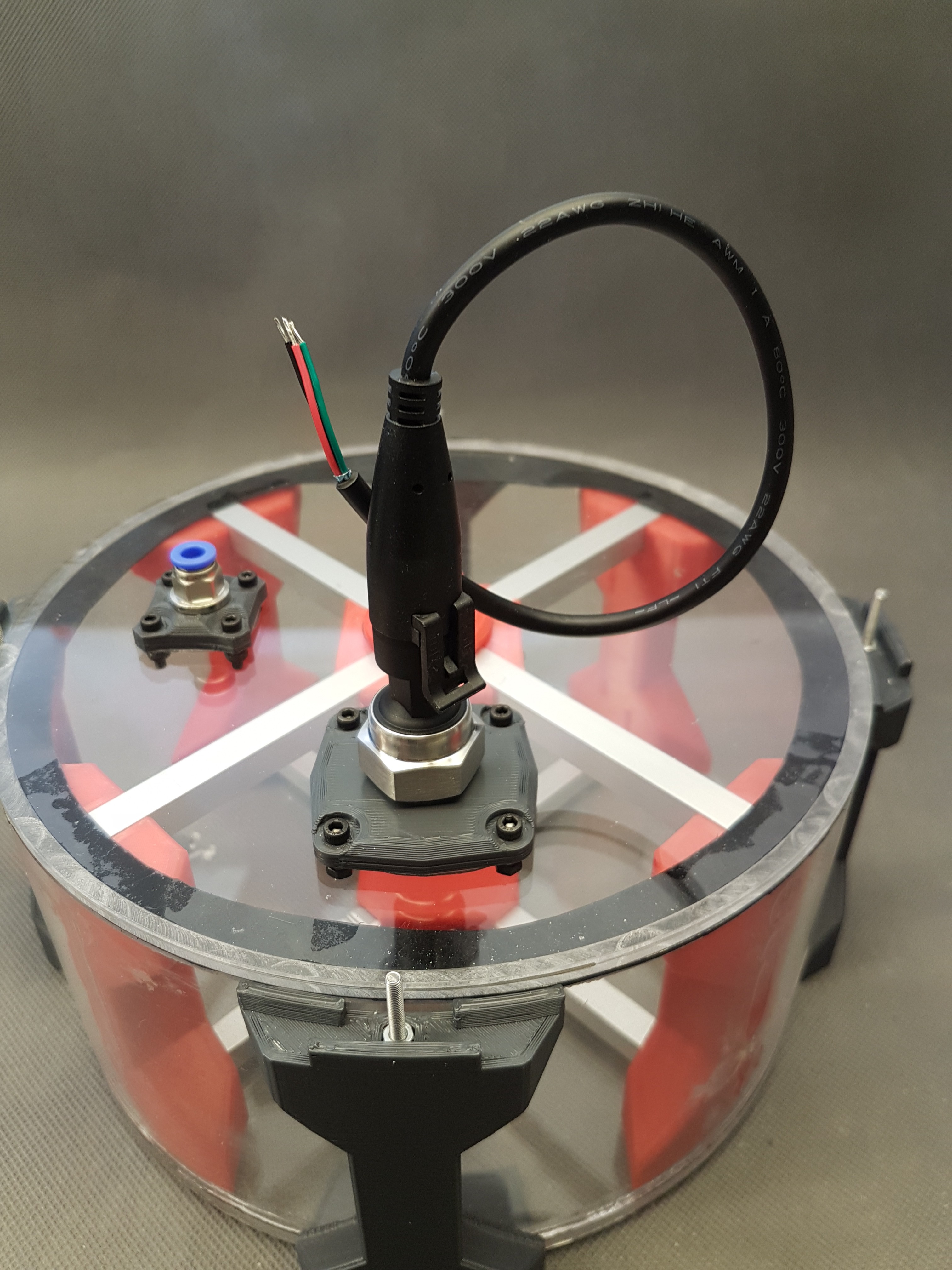
06/23/2020 at 17:31 • 0 commentsIn the last log I reported that when I was casting the magnets for the rotor disc, I had the problem of enclosed air bubbles in the epoxy. My solution to solve this problem is (hopefully) to pull the air bubbles out of the epoxy using a vacuum chamber. You can see a first (more or less advanced) attempt for a vacuum chamber here: https://hackaday.io/project/173340/details/
Picture of the build vacuum chamber:
![]()
The "Nerdiskerator-controller":
In addition, I have now made a few thoughts about the controller for the Nerdiskerator. Since the Nerdiskerator consists of 3D printed parts, which have special limits with regard to mechanical stress and temperature, I think it is good to be able to monitor these parameters and intervene if necessary.
For example, I think that winding temperatures that are too high could become critical. Also very high speeds. In order to be able to measure these values, various sensors are attached. In addition, actuators (such as the mechanical brake or electrical load) are also planned to be able to brake or stop the generator if the parameters are exceeded.
A first list follows here:
(I will also put them in the project details and update them if necessary.)
Sensors:- Speed measurement: via Hall sensor and detection of voltage zero crossing/frequency
- Voltage and current of the generator after rectification
- Temperature of the heatsink of the load resistors
- Measurement of the position of the brake cylinder using a sliding resistance
- Current consumption of the stepper motors (brake and pitch adjustment) to detect any blockage
- 2x limit switches to recognize when the brake cylinders are completely "open"
- RTC (for recording of log files)
- Accelerometer to detect abnormal vibrations
- Voltage and current measurement of the buffer battery
- Additionally:
- Compass module to recognize cardinal direction
Actuators:
- MOSFET for load restors
- 3x NTCs between the coils of two phases each
- Extra MOSFET to be able to short the windings of the generator completely (without the load resistors)
- Micro SD card slot to save log data
- Additionally:
- Stepper motor for pitch adjustment of the blades of a connected wind / water turbine
What do you think? Have I forgotten anything else? :)
-
The actual state, issues and how to solve them (hopefully)
06/20/2020 at 15:43 • 0 commentsIt's time for an update here. :)
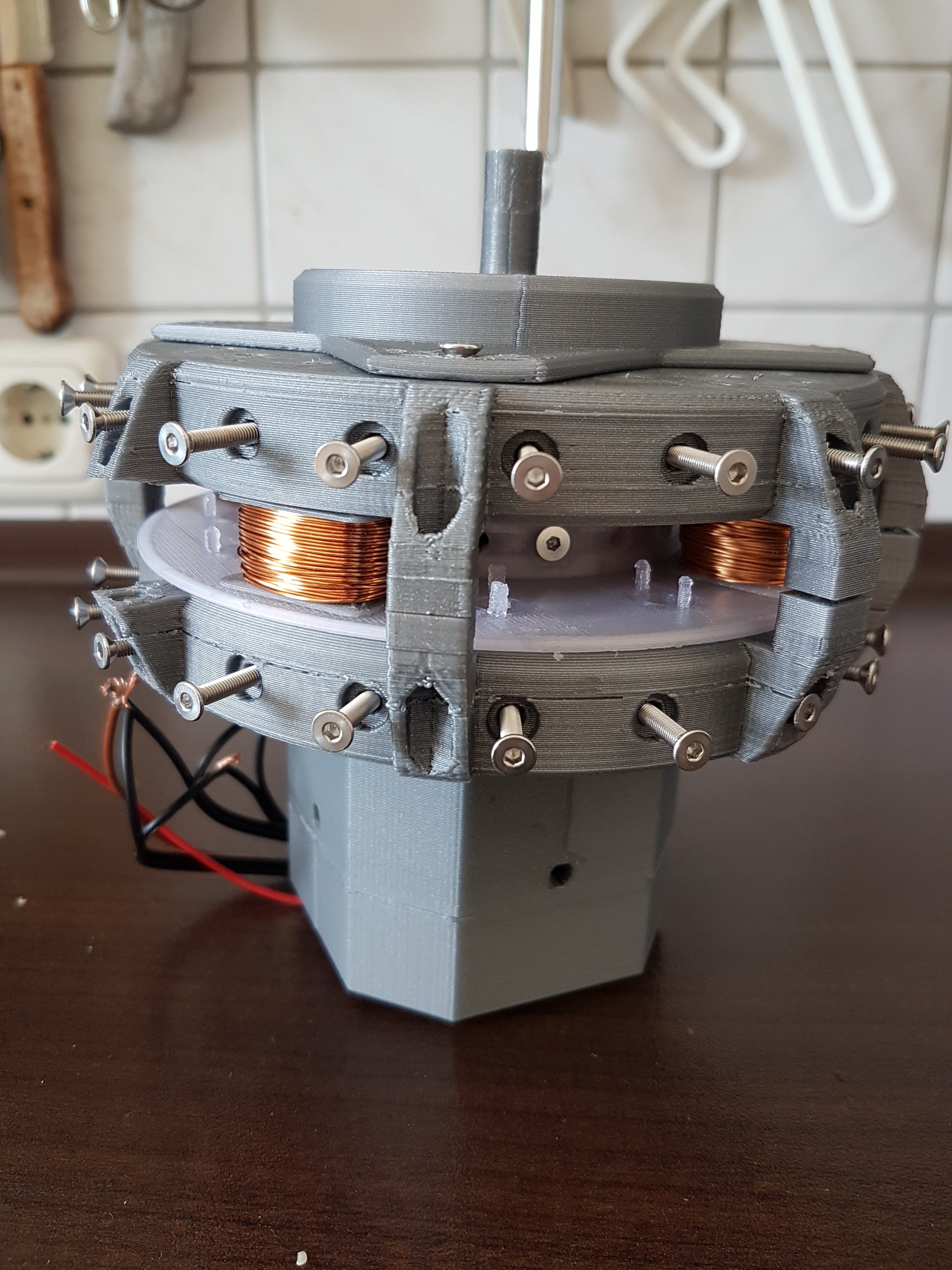
So far I've only posted pictures of the first prototype. To give you a little update about the current status here are a few pictures of the most recent build. There are also a few problems/"construction sites". For most of them I have already considered a few possible solutions. :)
The current state:
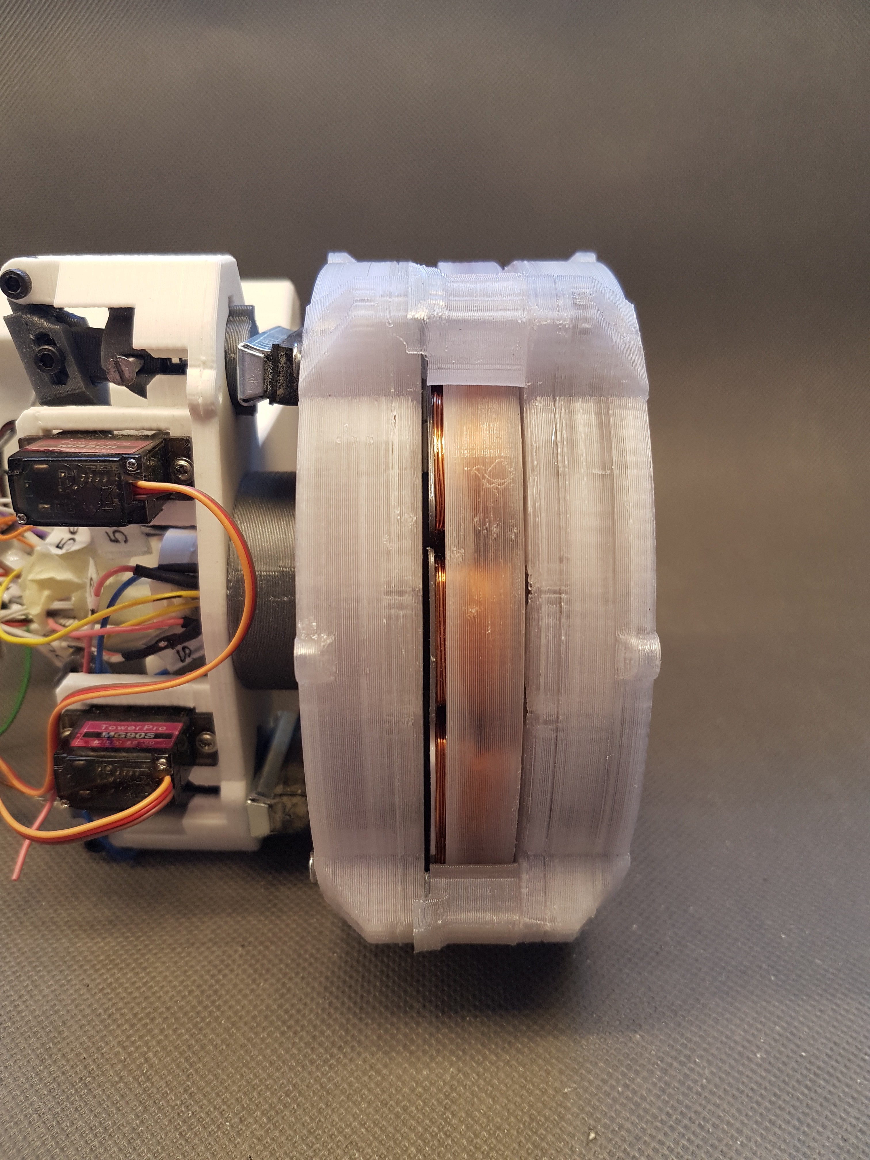
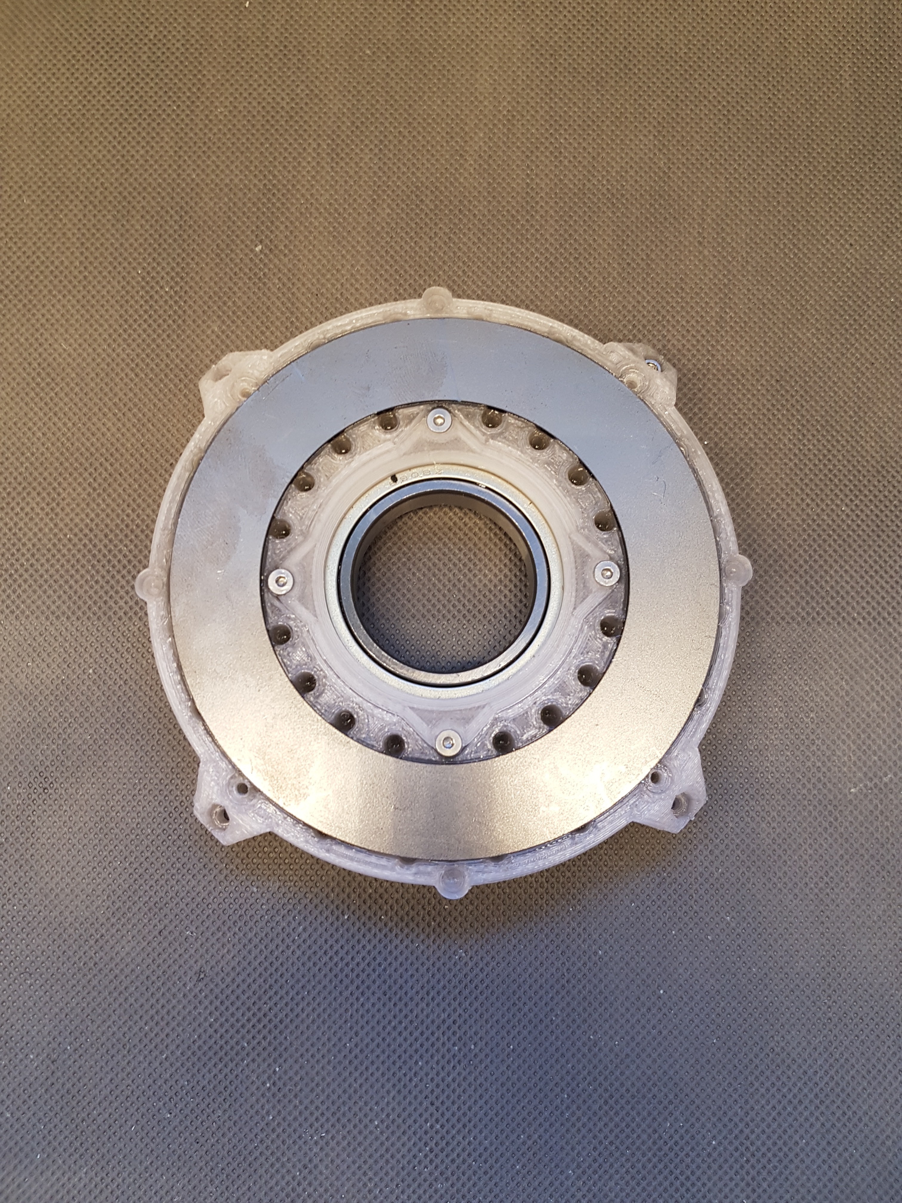
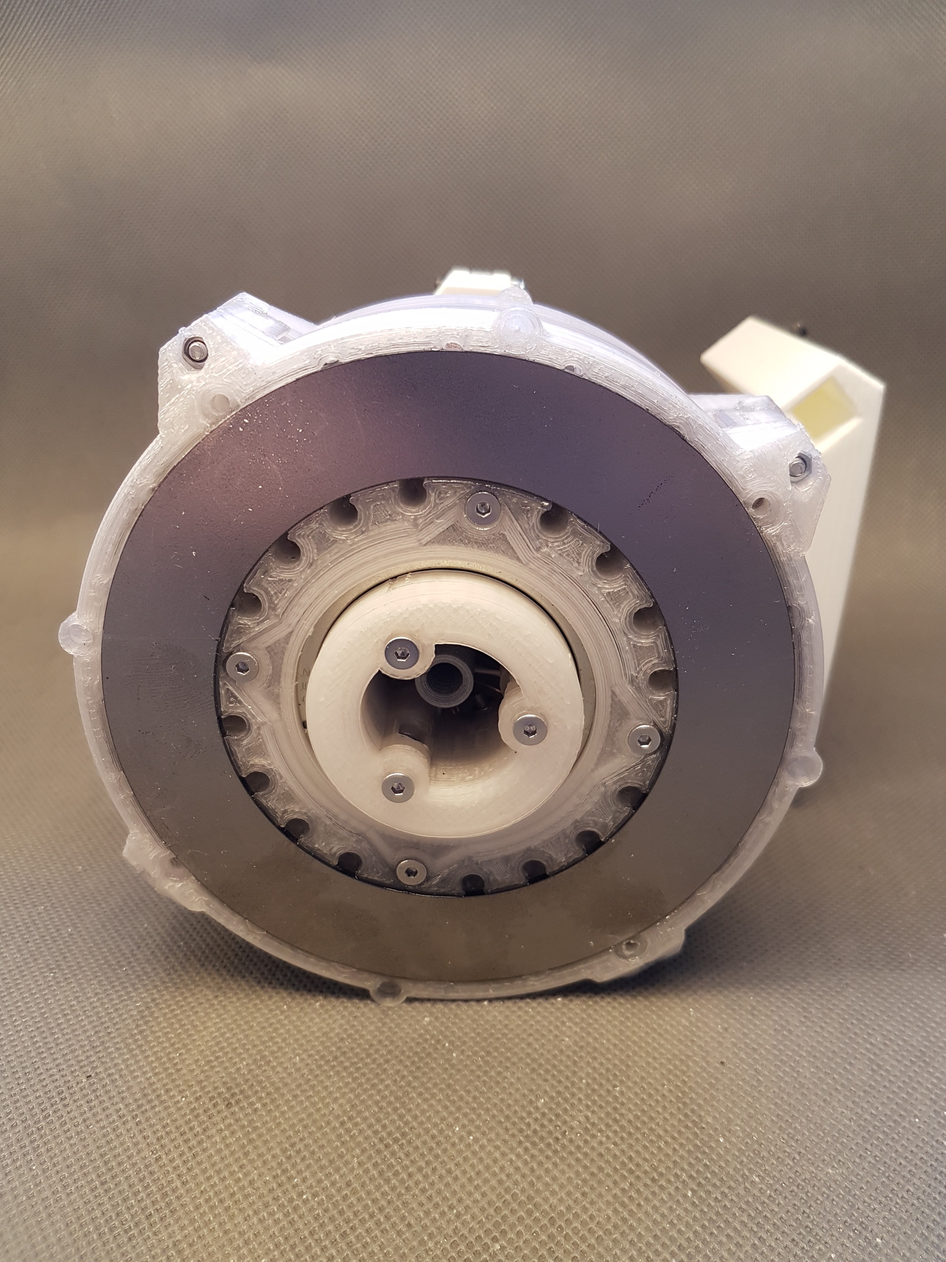
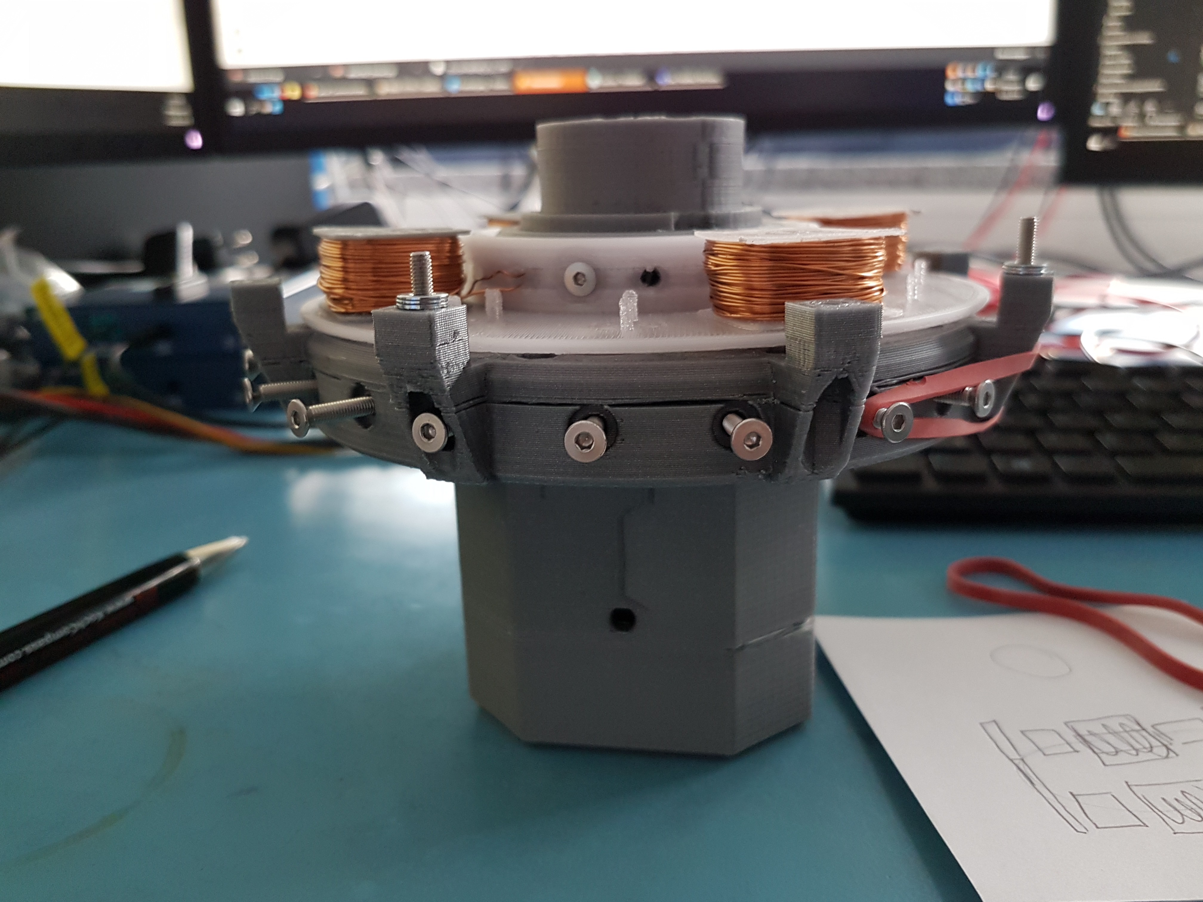
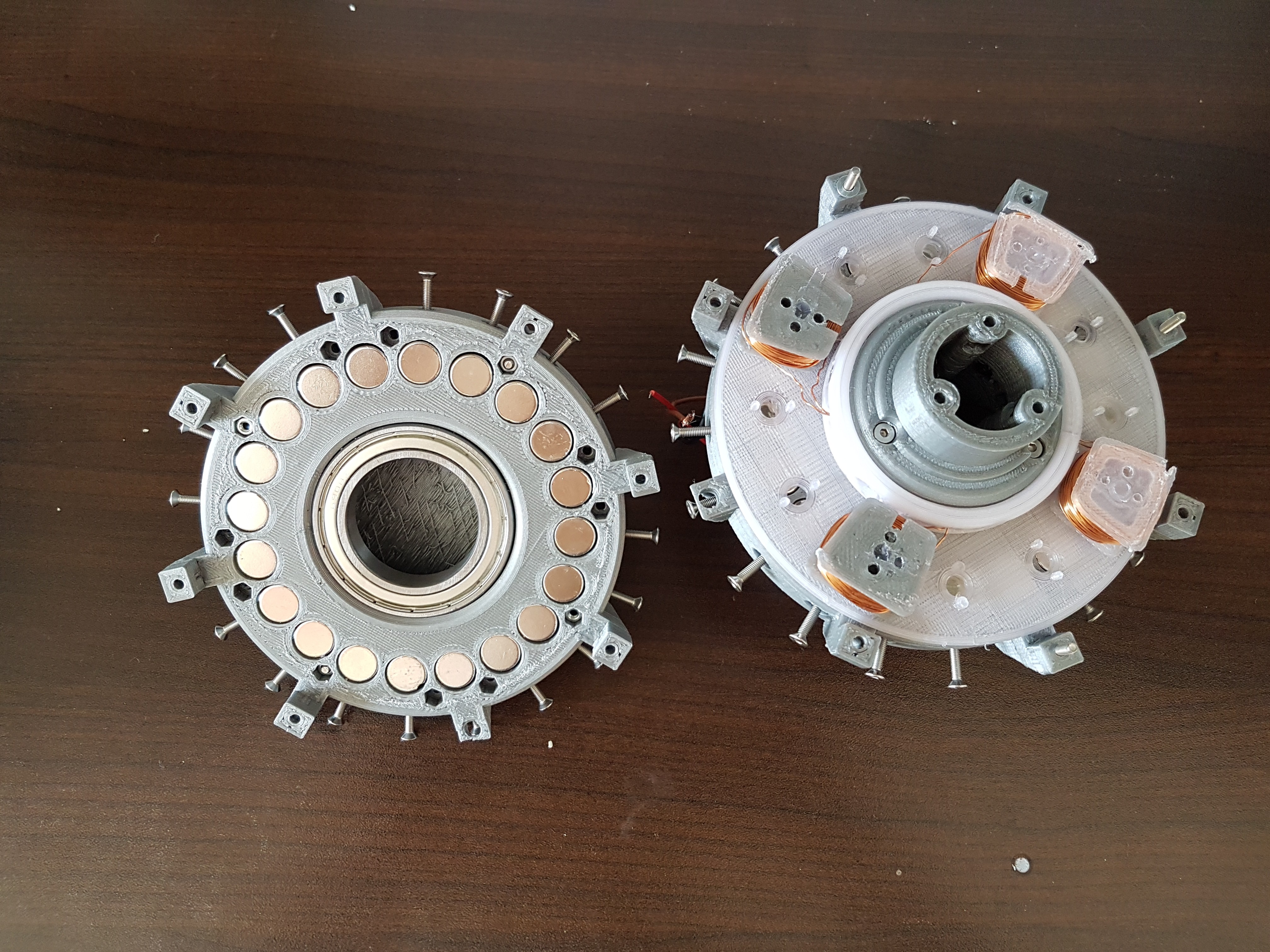
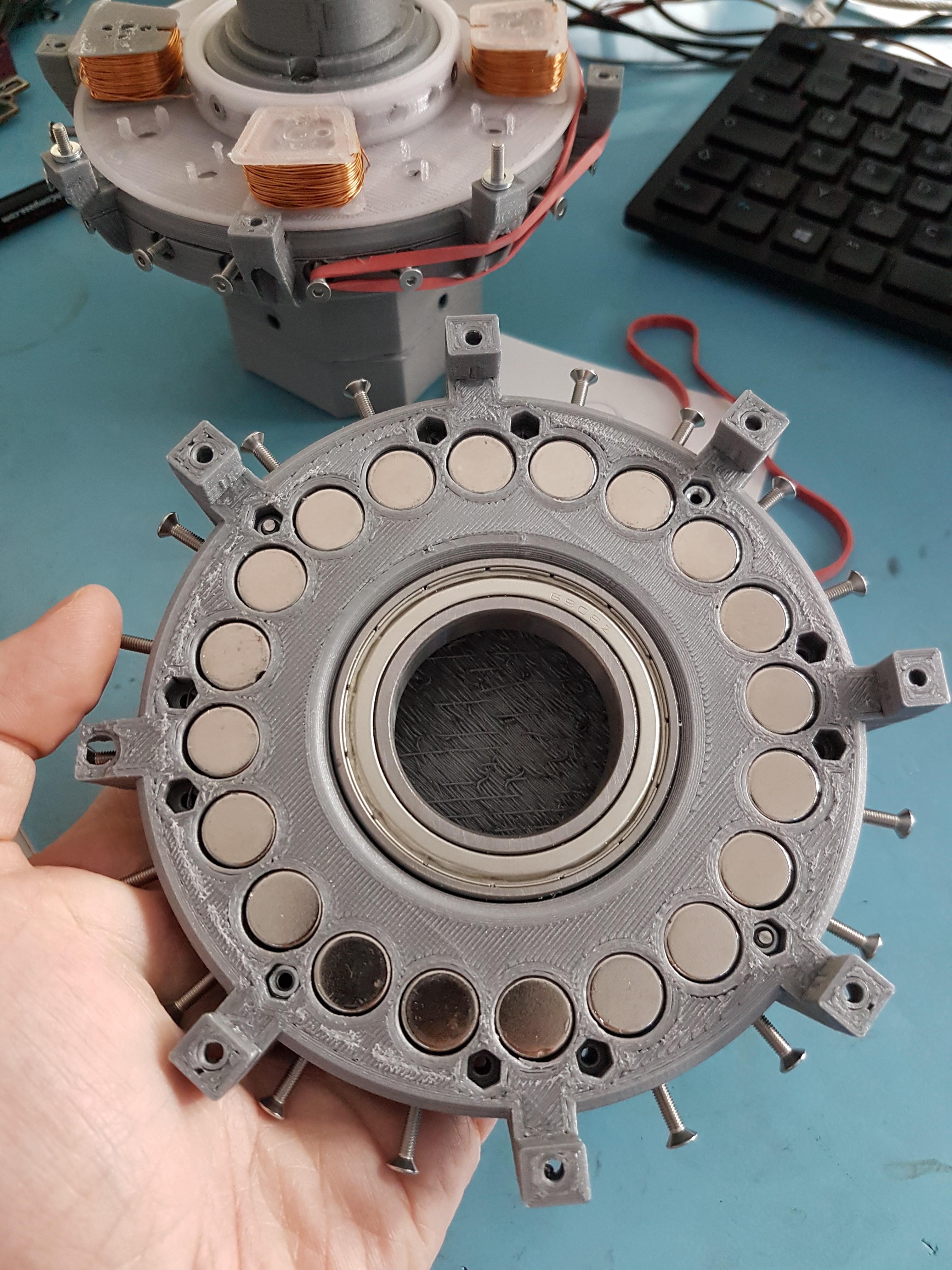
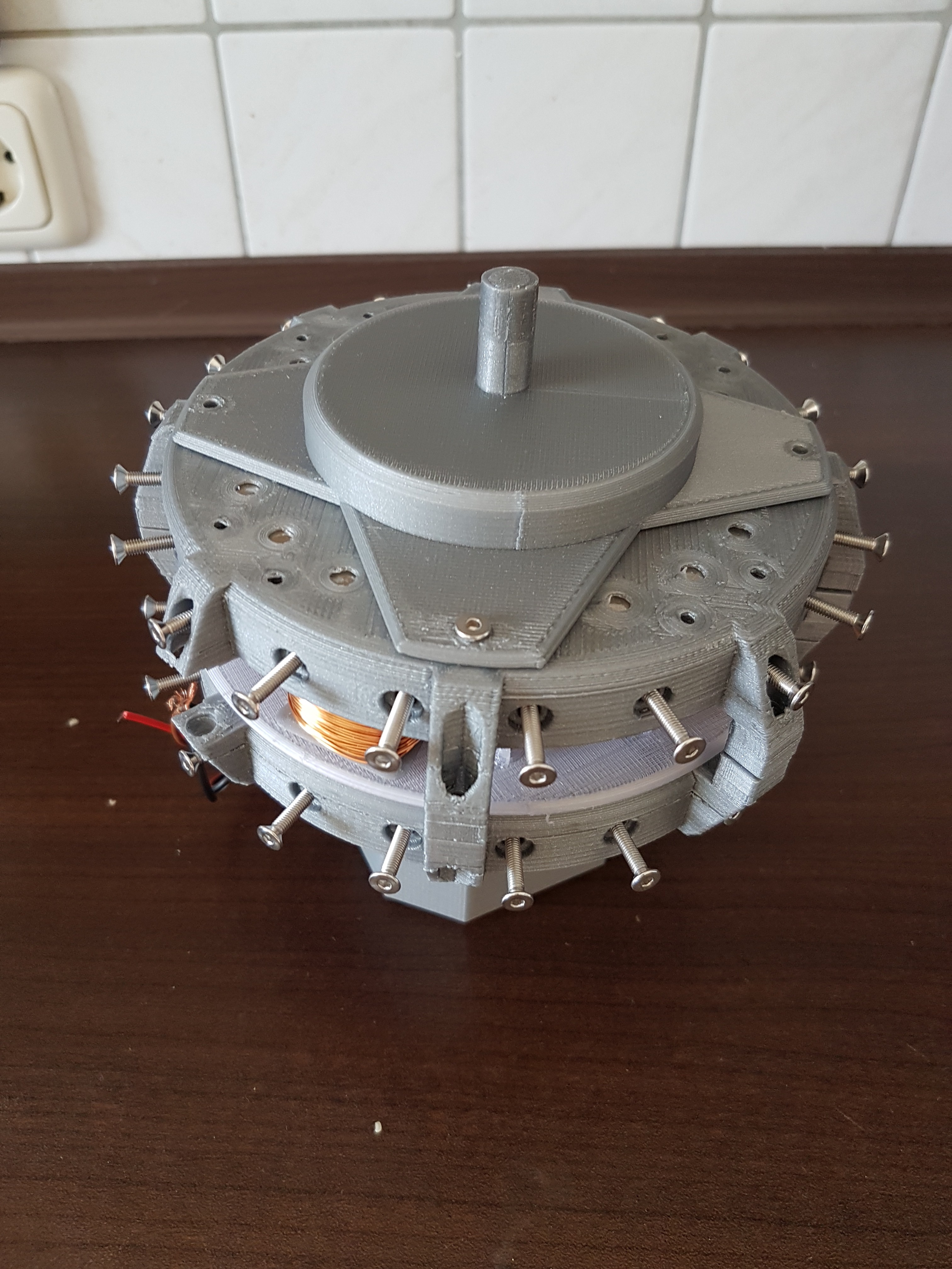
Here you can see the completely assembled generator in side and top view. I also removed a rotor disc (the disc that contains the magnets). Because this is where most of the changes are actually hidden.
A 2mm thick steel ring was installed on the outside of each of the two rotor disks. This has two and a half functions.The first function is that it short-circuits the magnetic field lines of the neodymium magnets. This has the advantage that the magnetic field of the magnets outside the generator can no longer have a strong effect on other lines. In principle, it is a kind of magnetic field shield.
The second function is that this ring can be used as a friction surface for the mechanical brake system. The brake shoes of the planned brake can brake the generator by pressing onto these discs. The steel surface should be much more durable than the 3D printed surfaces. :)
Half the function is that it makes installing the magnets in the rotor a little easier. The magnets can be screwed into the rotor using the ring and four screws. In this way, the remaining cavities can be filled with epoxy in peace.
Here the pictures. More about the issues a bit below. :)
![]()
![]()
![]()
![]()
Now for the first problem:
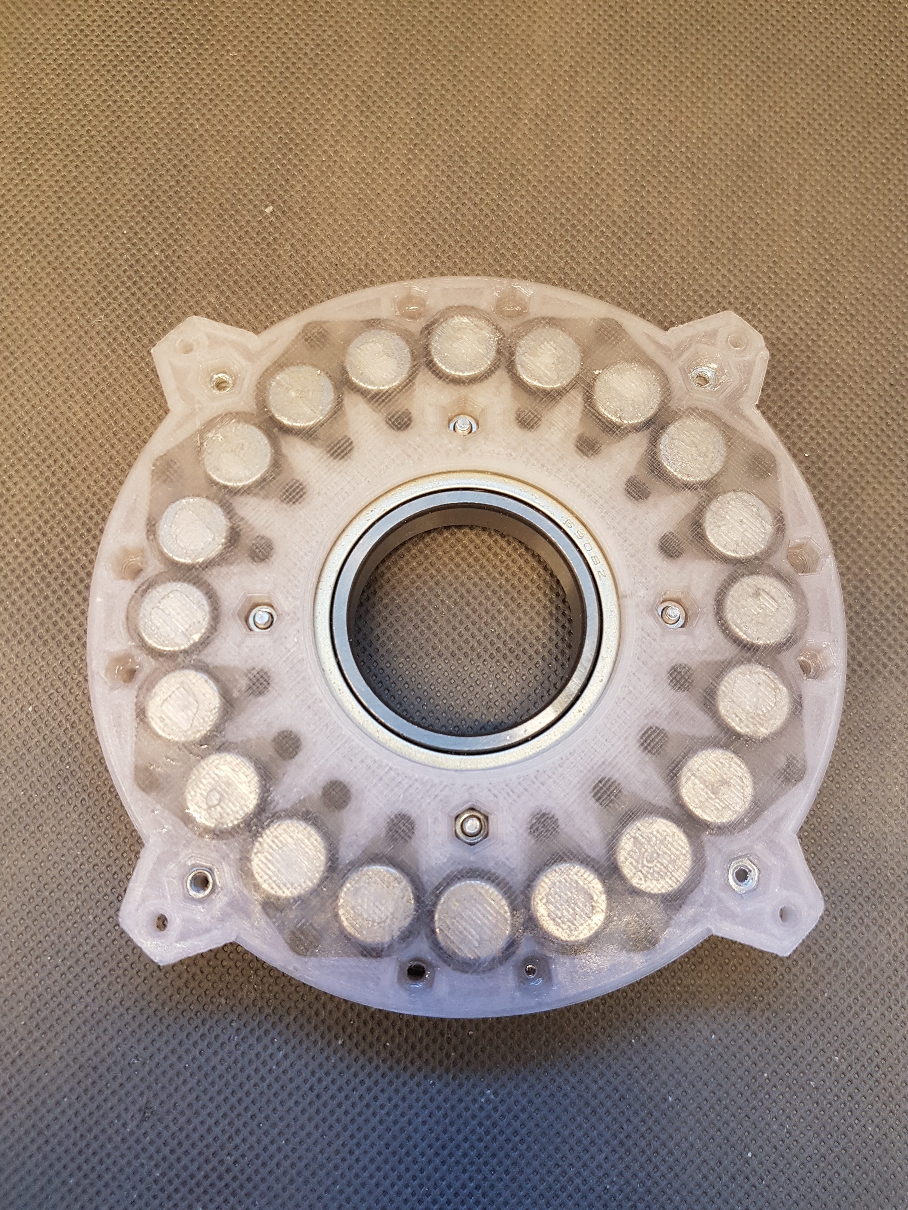
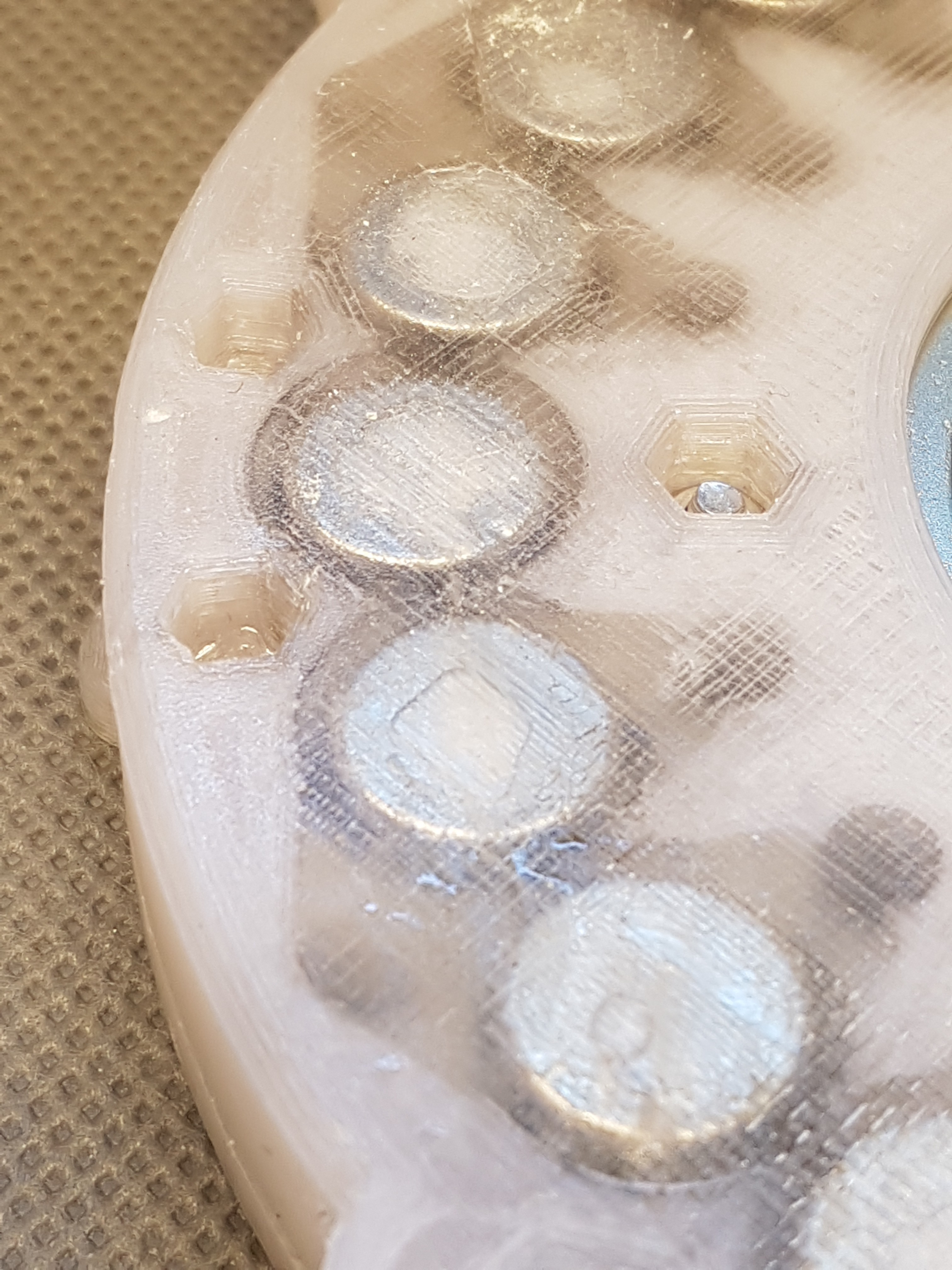
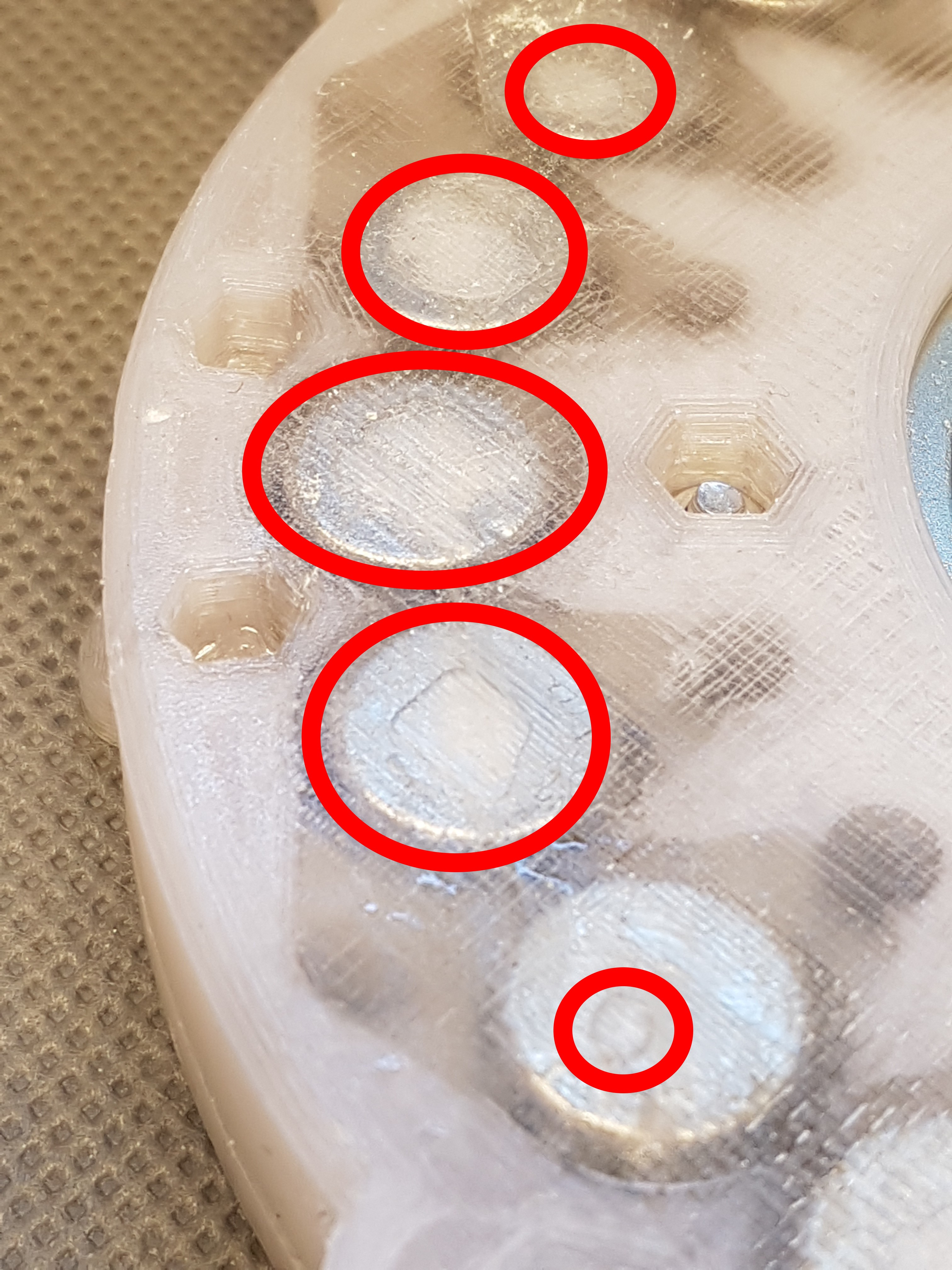
On these two pictures you can see that there are air pockets between the 3d printed housing and the magnets in the rotor disc. (I marked it on one of the pictures). This is not so great, because on the one hand it could increase the distance to the stator disc (this should be as small as possible, because this corresponds to the air gap in a generator) and on the other hand the magnets should be completely encapsulated from all sides in order to make the construction as stable as possible and more important to get an even weight distribution. Otherwise it could happen that the rotor develops an unbalance despite its symmetrical structure.In order to prevent this, I planned to expose the rotor disc to a slight vacuum for a certain time after filling in the epoxy and hopefully be able to pull all air bubbles out of the epoxy. I built a small vacuum chamber for this. (I will present it in another project log soon.)
I hope it works. :)![]()
![]()
The next problem:
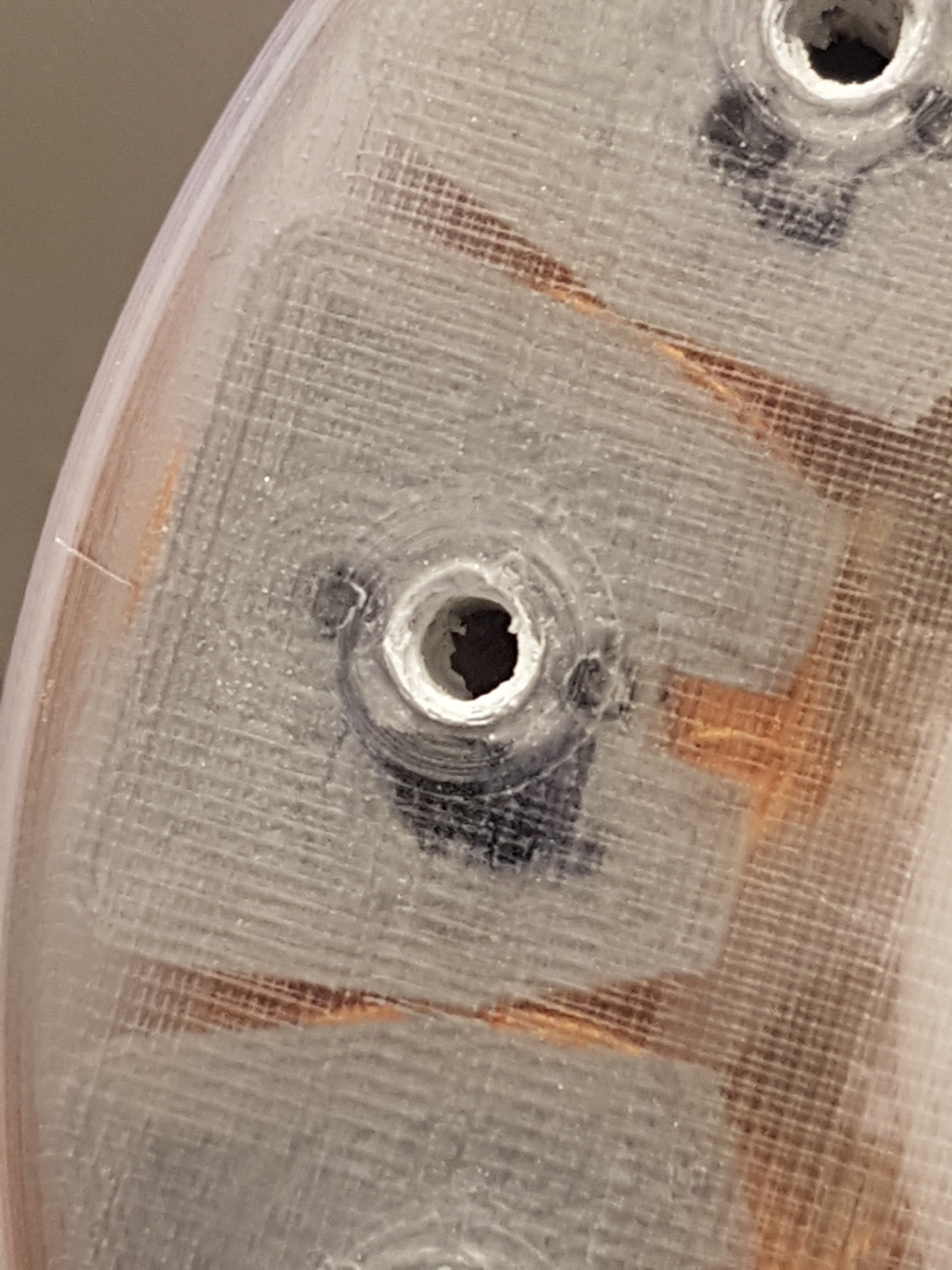
While filling the stator washer with epoxy, I temporarily screwed the coils onto the stator well with M5 screws. Unfortunately, this screw connection is not really tight, so that epoxy runs out of the screw-holes and out of the stator during filling.
To prevent this, I want to seal the screw holes with rubber washers. That should actually work. I'll see if it works when building the next version. :)
In the second picture you can still see that the hole with which the coils were fastened is interspersed with epoxy. At first it was quite difficult to remove the screws from the stator washer. : /
![]()
![]()
-
First prototype of the stator for the "Nerdiskerator"
06/14/2020 at 15:28 • 0 commentsUnfortunately I don't have that many photos from the first construction of the stator for the "Nerdiskerator". (I will add new ones as soon as I have built the second version) Back then, when I cast epoxy into the coils in the stator, I worked with epoxy for the third time in my life. That's what my table looked like, and especially my hands and gloves. So I didn't want to touch my camera so much. : D
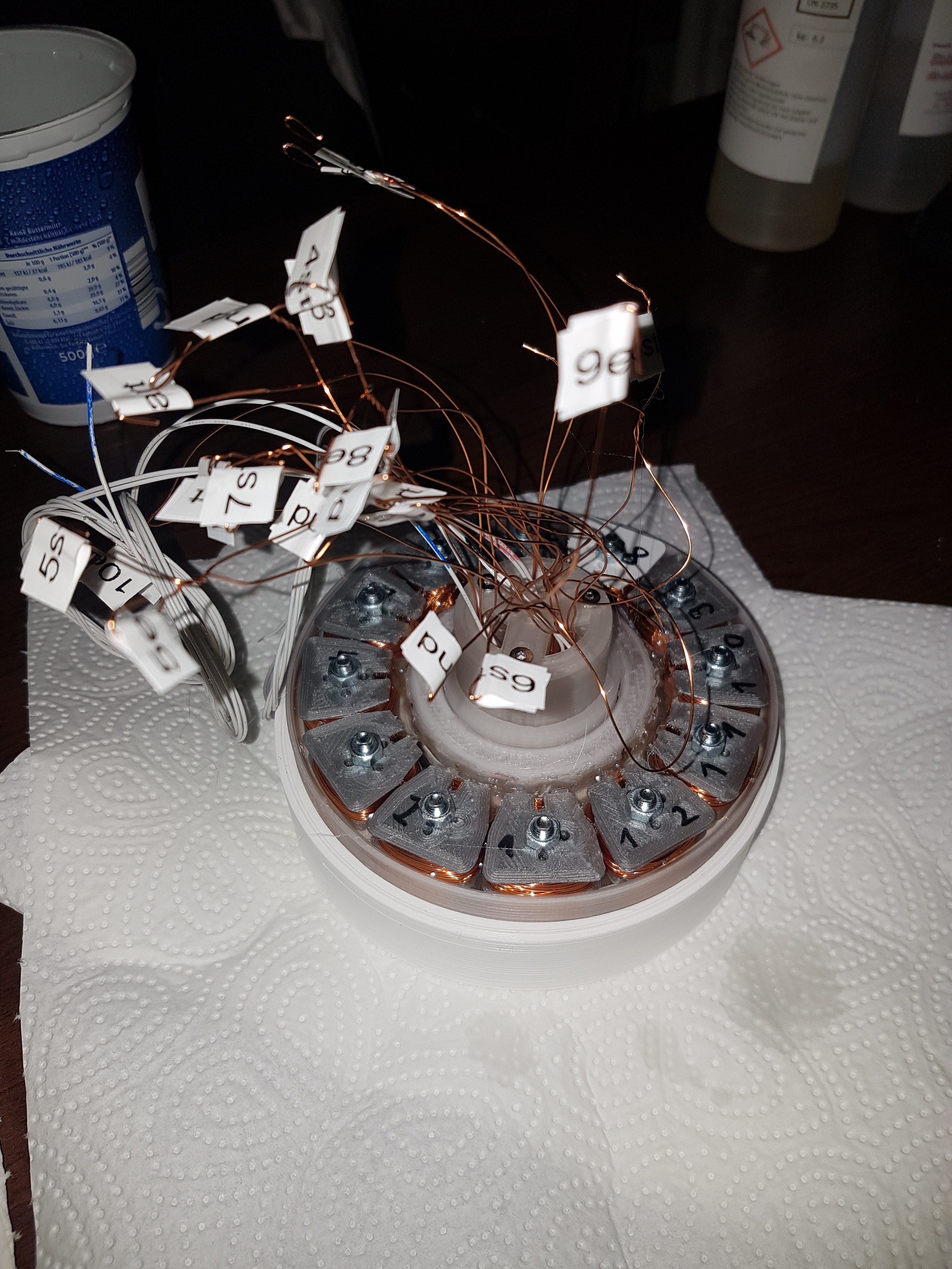
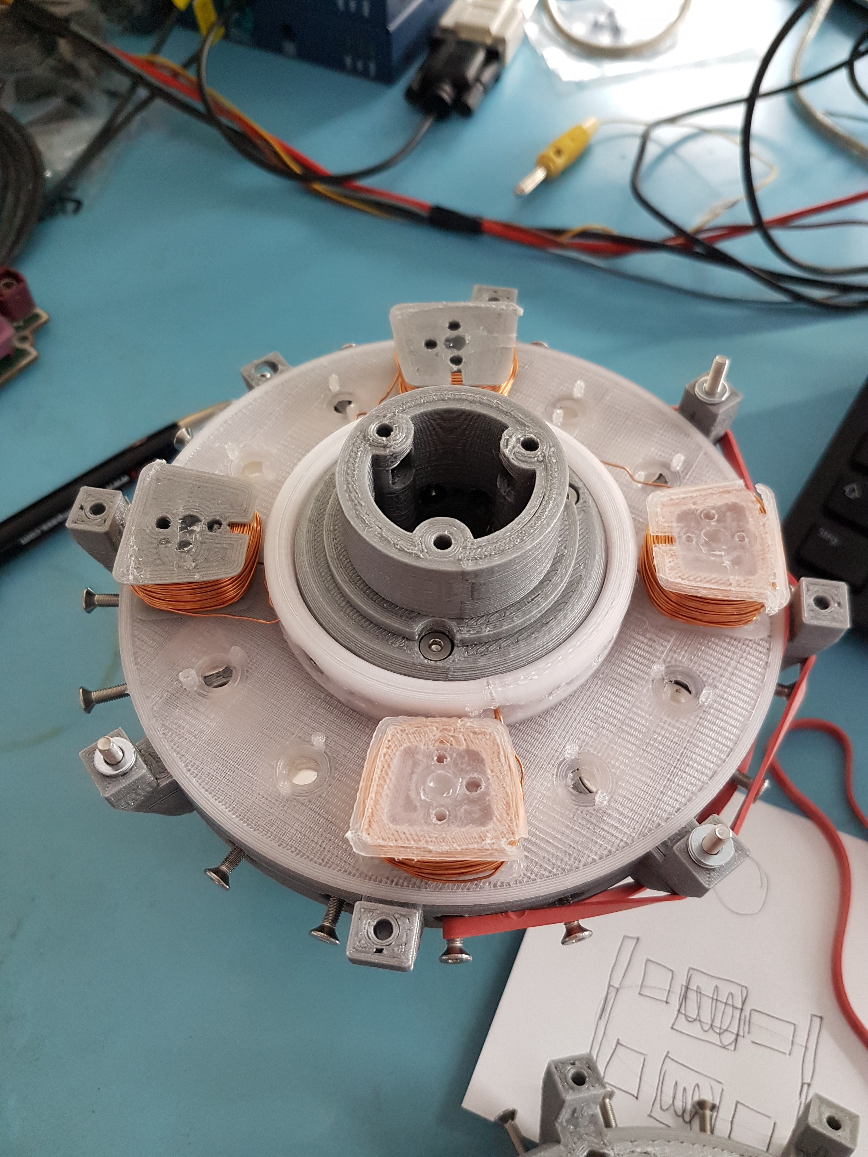
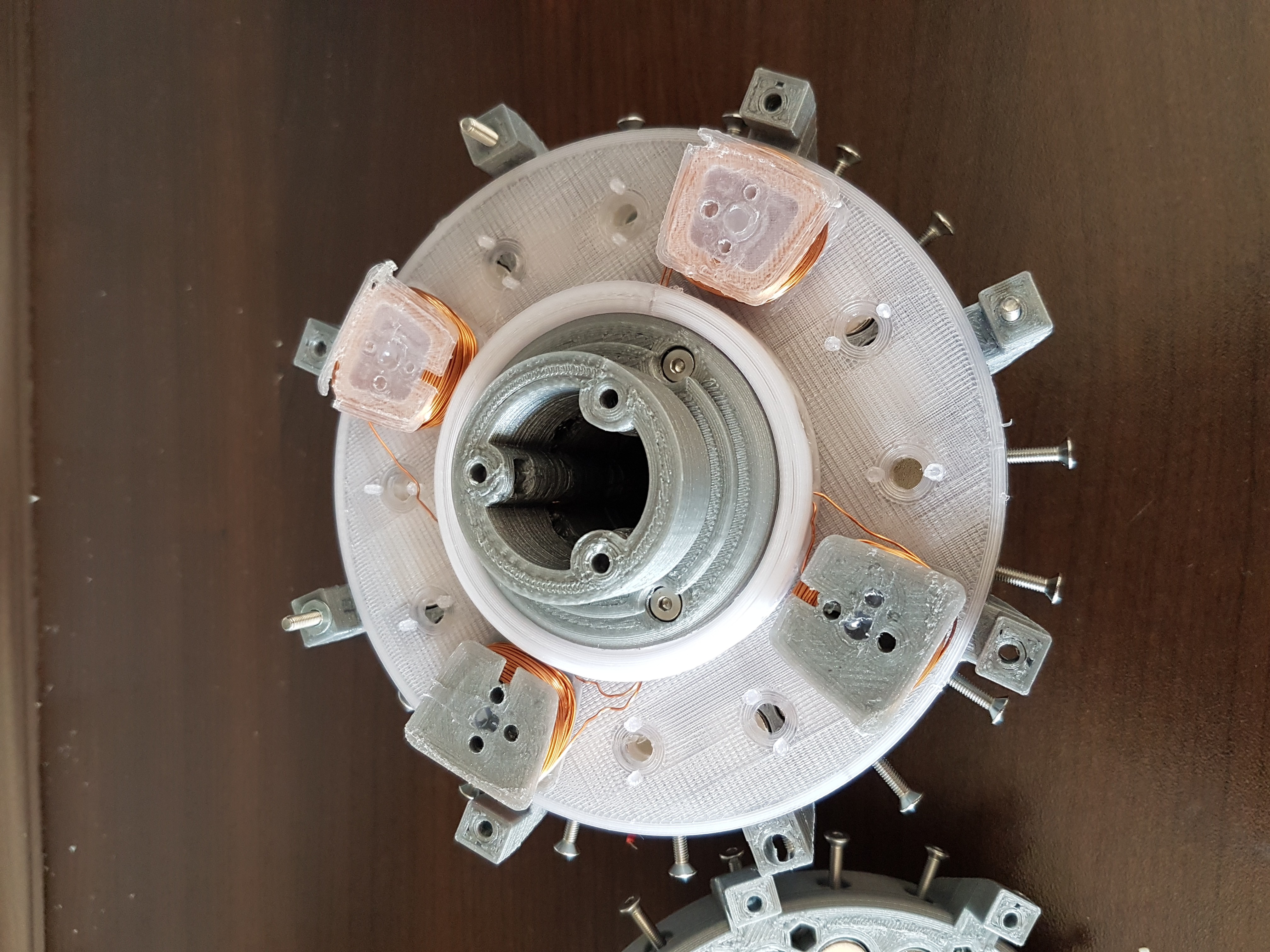
In the photo you can see the twelve wound coil cores, which were cast with epoxy in the stator shell. So that they stayed in place for the time of assembly, I first fixed each coil with a screw.
These screw holes could also be used later to expand the generator coils with an iron core. However, because of the resulting strong cogging torques (the magnets of the rotor always turn over the coil cores) I wouldn't use these iron cores at WinDIY. But if you later want to use the "Nerdiskerator", for example in combination with a water turbine (which should have significantly more initial torque), you could increase the energy yield with the help of the iron cores. :)
In the video you can see the first tentative turns of the "Nerdiskerator" prototype. the two rotor disks are each held by a ball bearing.
![]()
-
Coil cores for the "Nerdiskerator"
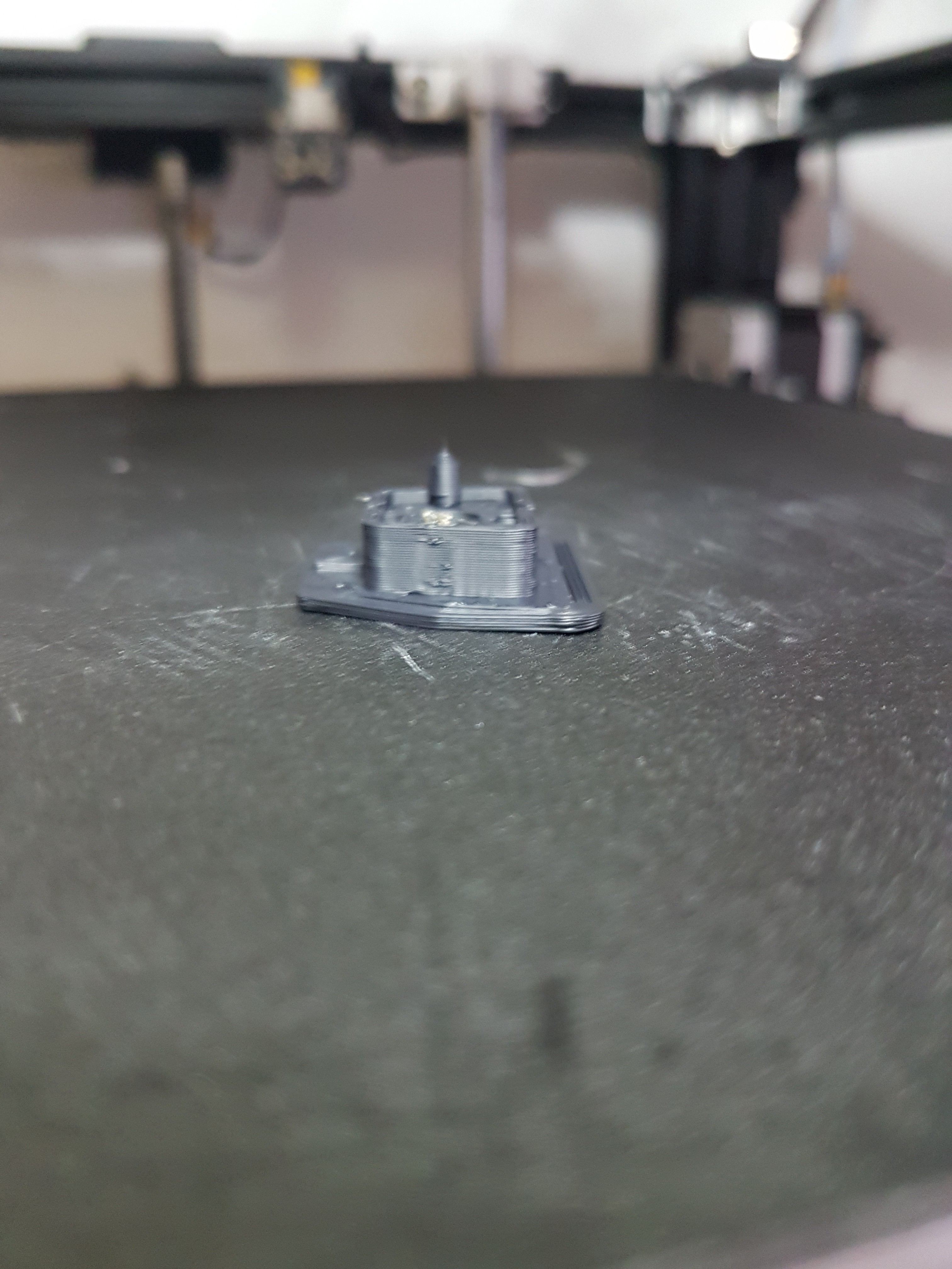
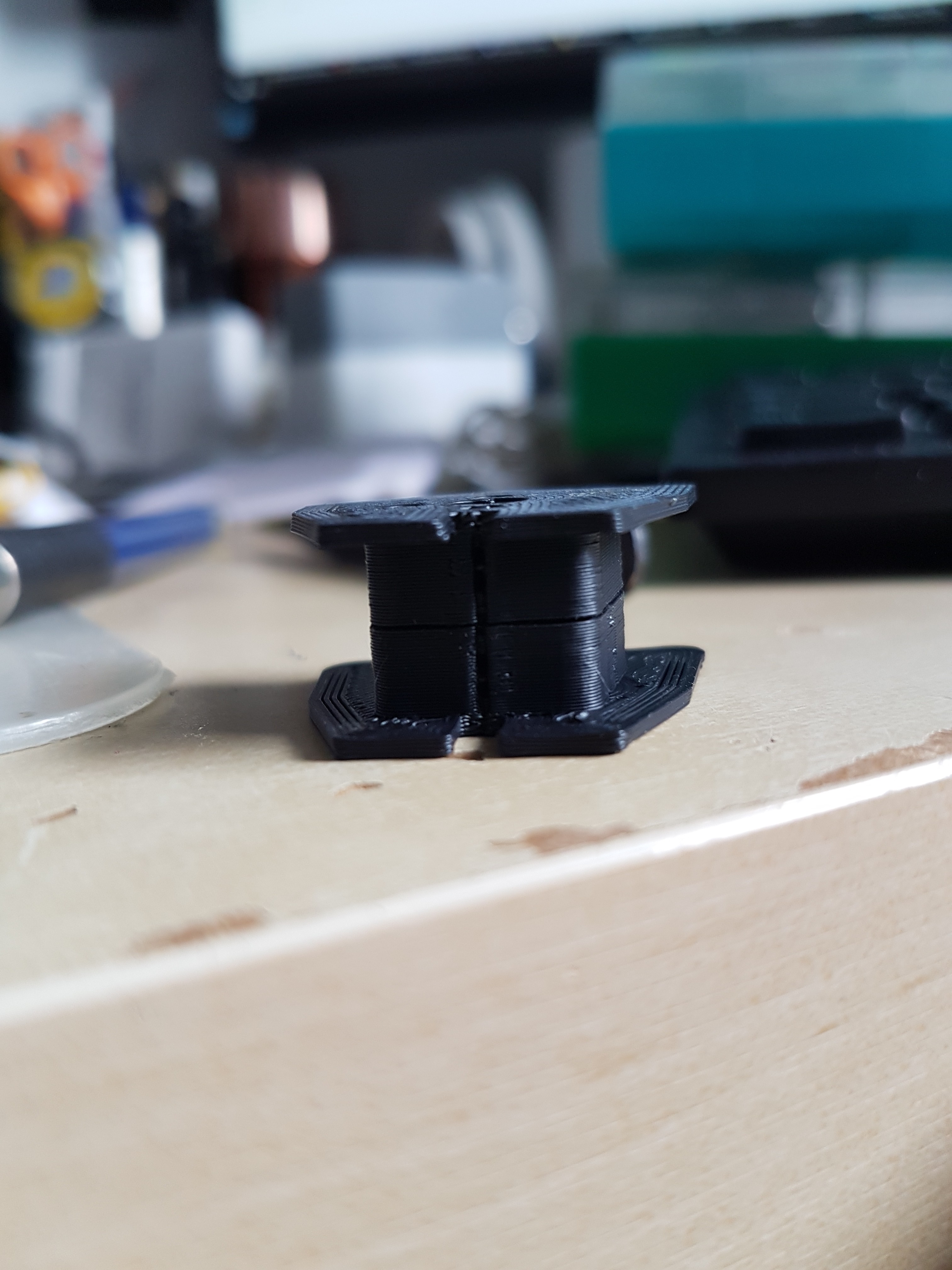
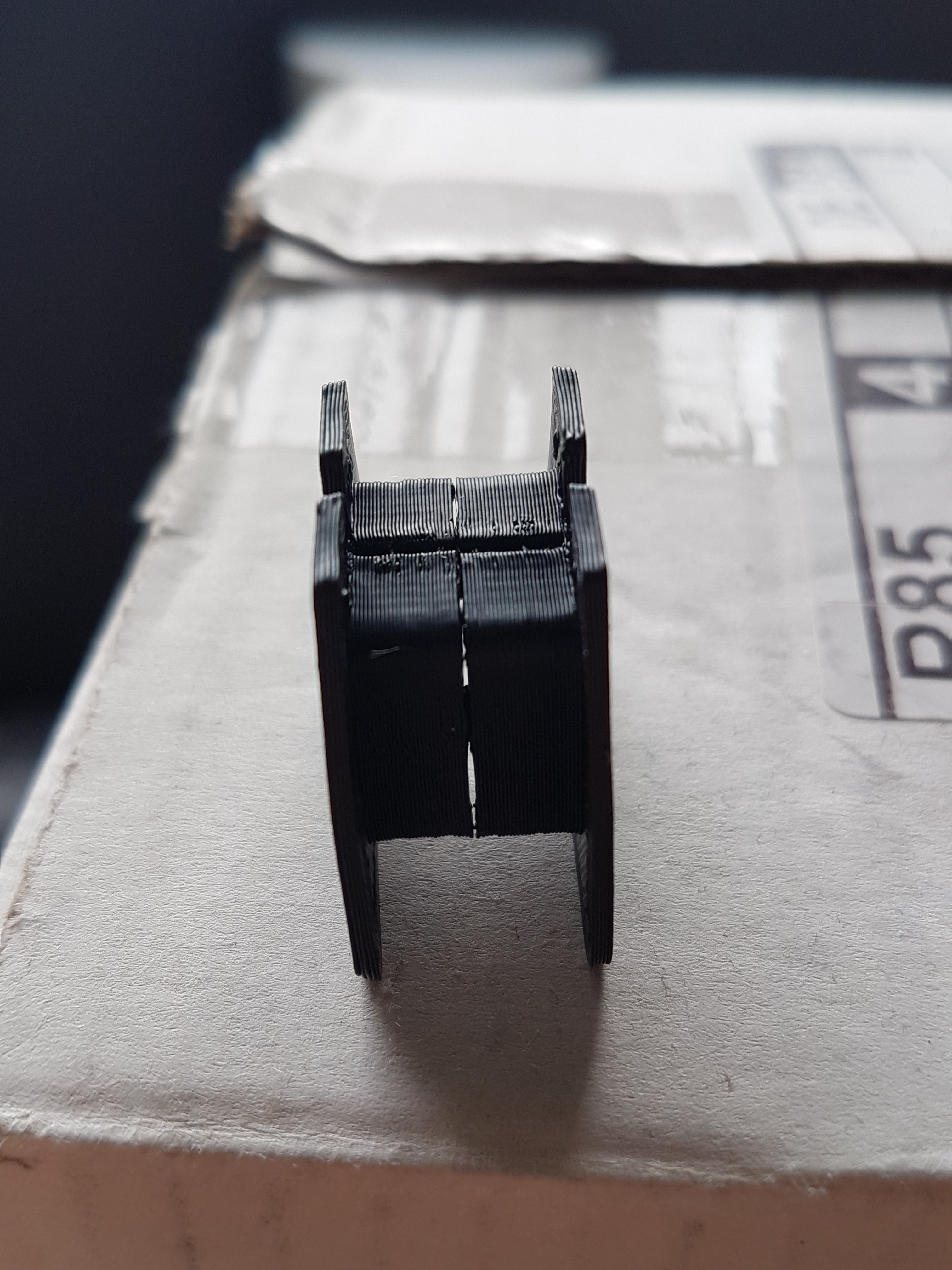
06/14/2020 at 15:24 • 0 commentsWith the coil cores for the "Nerdiskerator", I struggled a bit with the disadvantages of FDM printers with overhanging structures. Because even with support material, the overhanging structures were never as precise as i needed7wanted them. That's why I finally decided to build the coil cores from two individually printed halves. These are put together after printing and temporarily held together with some adhesive. Since they are later cast with some epoxy in the sator, the adhesive only has to hold the two halves together up to this point. But more on that later. :)
At filament, I experimented with ASA filament for the first time. I usually print with PLA. However, I am afraid that with higher power the temperature in the coils could rise and thus deform the PLA. To prevent this, I want to use the ASA filament for the coil cores and maybe also for the stator. Thanks to the significantly higher melting temperature and the generally higher strength, this should prevent the stator from deforming at higher powers.
In order to be able to monitor this during operation, three NTCs for temperature monitoring are cast between the coils in the stator. :)
![]()
![]()
![]()
-
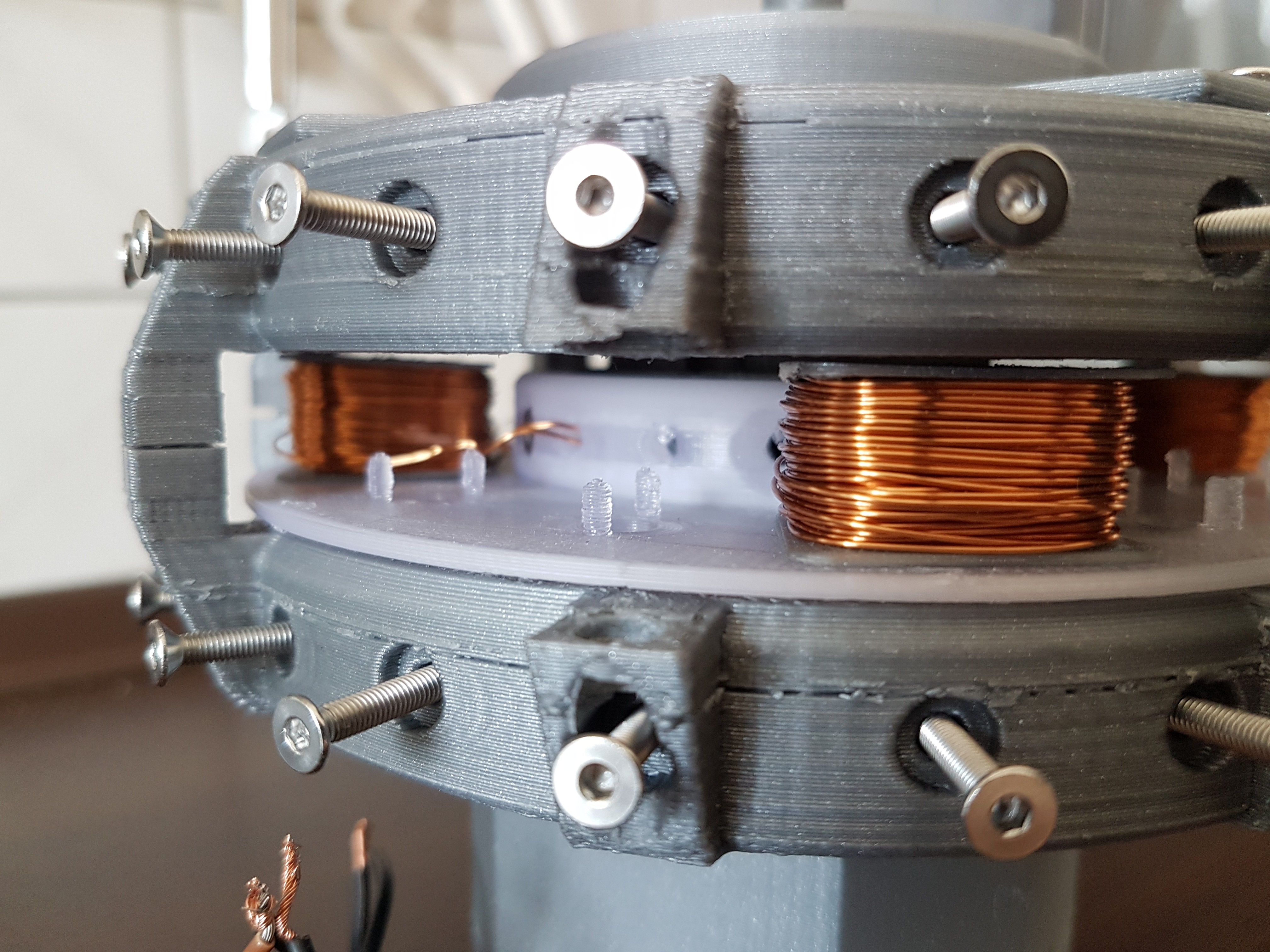
"Nerdiskerator" = NERdiys DISK genERATOR -> The 3D printed disk generator
06/14/2020 at 15:21 • 0 commentsAt the same time (or whenever I got stuck with the wing), I had already started developing the associated disk generator. I wrapped it around the neodymium magnets that I already had at home. With a length of 13mm and a diameter of 13mm (cylindrical shape), these do not actually correspond to the typical magnetic shape for disk generators. But back then I still thought that this would be a small weekend project for which I would not need to buy extra magnets. : D
For the first design, I only fixed the magnets in the rotor with screws. For this purpose, the rotor did not get all twelve but only four coils. So at least I had already set up a test phase.
A first test with the cordless screwdriver showed an electrical output power of ~ 23W. There is certainly more here. But I think that the cordless screwdriver was not able to deliver more mechanical power to the shaft of the generator. More mechanical power would of course also lead to a higher electrical output of the generator. :)
![]()
![]()
![]()
![]()
![]()
![]()
![]()
![]()
Nerdiskerator - A 3D printed disk generator
This is a mostly 3D printed disk generator build from 40 neodymium magnets and 12 self made coils
 Fabian