Josh Cole
-
Introduction
06/17/2020 at 02:43 • 0 commentsHello!
Welcome to my project. Here I want to spend a brief moment to outline some of the project goals, and describe a few of the meta parameters that I'm working with.
This robotic arm is entirely (well, almost entirely) designed with SolidWorks and is my foray into complex mechanical part design. I have been creating 3d printable things for many years, but some of the nuances of moving parts have eluded me.
So far, some of the skills I have learned as a result of this Robotic Arm project include:
- Gearbox design and how to distance everything
- How to affix a shaft to a bearing
- How to press-fit a bearing into a 3d printed part (and what a reasonable tolerance for such an activity looks like)
- Common interfaces and captive-nut designs for connecting parts together
- Using fillet makes things look instantly cooler
- Introductory SolidWorks
I'm sure there are even more takeaways, which I shall reflect on in the future.
A secondary (but equally important) goal is to improve my own ability to be an effective communicator. In the spirit of that goal, I will be creating more videos and documenting a finer grain of my project than I traditionally have. That being said, I am getting a late start. So I will be speed running the first few log posts.
As far as functionality goes, I am not expecting this machine to be particularly useful "in the field". It's intended life purpose is to employ advanced mathematics which enable smooth path-following and route finding to, um, point a camera phone in a specific direction. It's... it's a gimbal. But a very precise gimbal.
This is an exciting project for me and I hope to share the interesting journey both past and future.
-
Axis 1 - Part Design - Planetary Gearbox
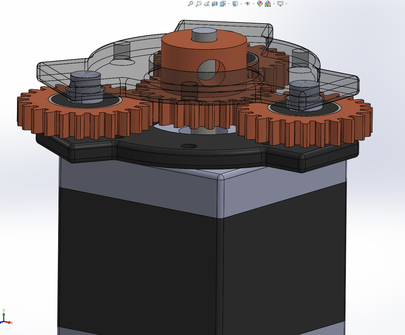
06/17/2020 at 02:28 • 0 commentsAxis 1 - Planetary Gearbox - 3:1 Ratio
In order to control the center of gravity/mass, I wanted the first level to be a planetary gearbox. In this way, I'm starting out with the weight being exactly centered along the shaft of the motor.
Spoiler alert: I forsake this dream of perfectly balanced construction a bit later.
The sun and planet gears are 24T and the annular gear is 72T. Their powers combined create a ratio of 3:1. Paired with my NEMA17 400-step stepper, this will give me an accuracy of +/- 0.3 degrees of resolution. Is that good? Ahh I'm not sure. But we can always revisit this part later!
Mounting Strategies
The sun gear attaches to the motor through a standard set screw. So far I have managed to make Axis 1, Axis 2, and Axis 3 consistently use 6mm set screws. So that is the "standardized" size and it applies here.
The planetary gears have a press-fit bearing installed. Apparently the tolerances needed for a successful press fit are just to make the bore exactly the expected OD of the bearing. My printer is generally off by +/- 0.15mm so this produces a slightly smaller hole then expected. As a result, you can use a press to snugly push the bearing in place.
Lastly, I created some spacers for the top and bottom, to keep the bearing in place.
Reflection: If I were to design this again, I would try hard to avoid the spacer design. In fact, I would probably play around with custom shaft design which has built-in spacer. Will likely work much better.
All of this is sandwiched between two standard planetary gear mount structures. The bottom structure has a NEMA17 mounting holes, as well as some captive nuts on the underside which the top structure bolts down into. The result is this lovely and very strong planetary gearbox.
![]()
Yet Another Robotic Arm
Entirely 3d-printed robotic arm created from scratch.