-
Scrapping Project
08/18/2021 at 19:15 • 0 commentsI've decided to scrap this project in favor of using IEEE 1588 PTP for synchronization of the receivers. Reducing the cabling to solely Ethernet reduces both the cost and the complexity.
-
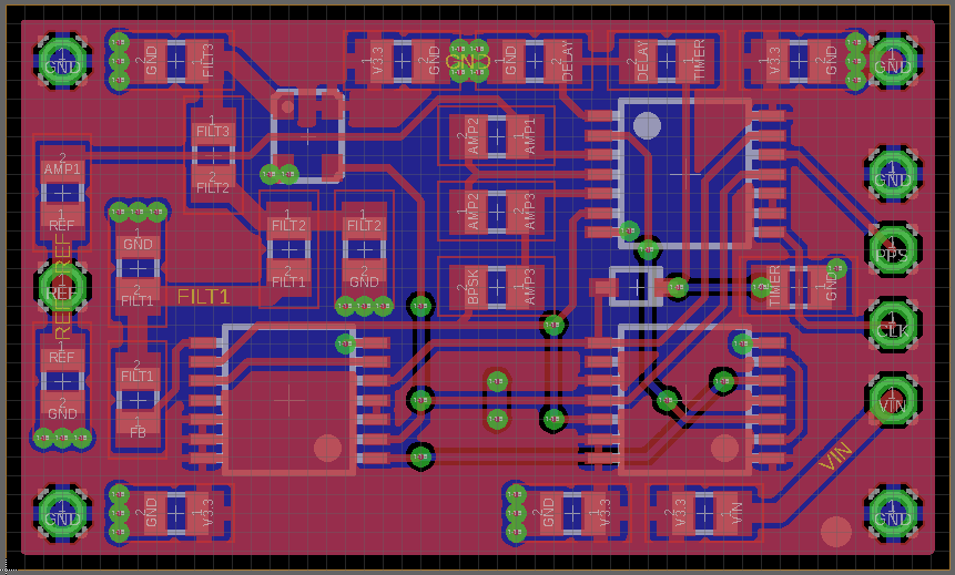
New layout sent to fab.
07/01/2020 at 19:15 • 0 commentsI've submitted the revised layout to OSH Park for fabrication. The new boards should arrive in a few weeks.
![]()
The only change is to the PPS polarity detection which required an additional resistor and diode to make the PPS timer reset asymmetric.
-
Initial Testing
06/19/2020 at 00:32 • 0 commentsI assembled the circuit boards today, and started some rudimentary performance analysis.
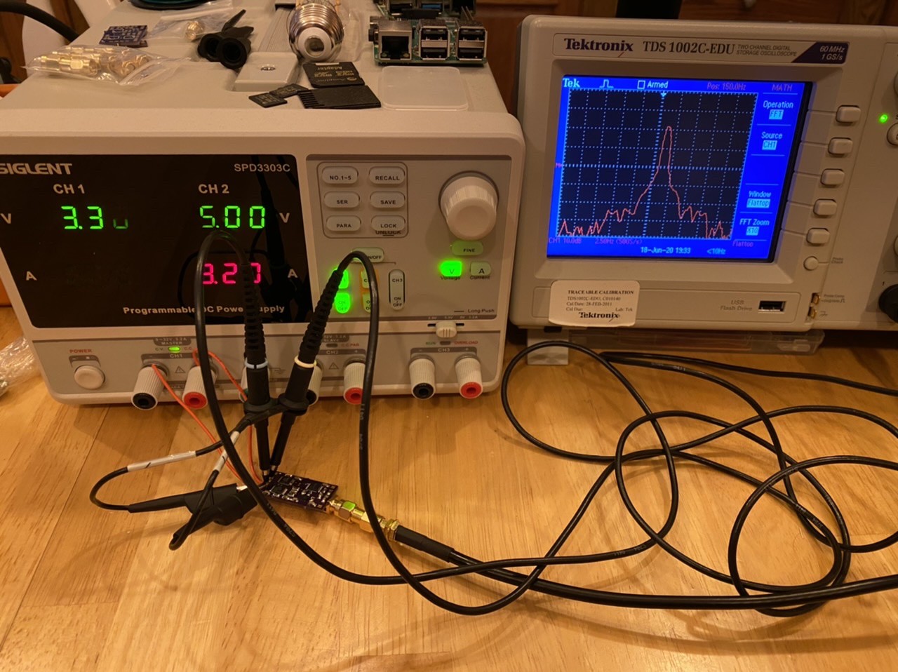
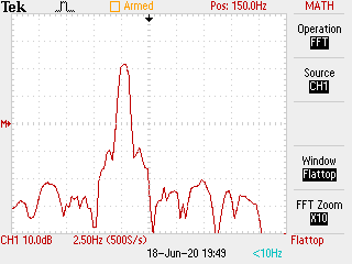
The additive phase noise appears to be negligible, and is actually drowned out by the phase noise from the GPSDO PLL adjustments. The phase noise bandwidth appears to be less than 2 Hz over four seconds, but for longer periods the results become blurred by the GPSDO correction drift.
![]()
I managed to catch the power supply mid display-scan, but it is set to 3.3V and the board is drawing 60mA. Here's a screenshot from the scope. The internal crystal reference of the scope is offset by about 150Hz which makes it possible to use under-sampling to measure the ultra-fine bandwidth of the clock output. You can see between the two images that the scope crystal frequency has drifted up about 4 Hz.
![]()
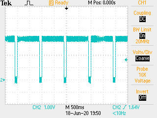
The polarity detection part of the circuit does not function correctly, so I'll be sending off a board revision to correct it. The PPS duty cycle should be 10% not 90%.
![]()


