Dan Jilek
-
A Battery Solution
01/21/2021 at 20:42 • 1 commentWhile I'm waiting for my boards to show up, I put in a DigiKey order and thought about how to power this rig. The pack of NMH batteries used by the original hardware wouldn't exactly cut it even if they hadn't leaked everywhere. Some of my designs use the MCP73871, which is fairly easy to use and works great for lower power systems, but doesn't support the kind of amperage an entire notebook computer will need. Ideally I would roll another design with a stronger output, but I just don't have the mental bandwidth for that right now. This has been a sticking point with a lot of portable designs in the past, but fortunately, a number of commercially available options have cropped up that should meet my needs.
As an IT guy, I have the typical distinction of being the person friends and family call with computer related questions and issues. This has lead to the refurbishment of various laptops: SSD/RAM upgrades, screen and battery replacements, etc. If you're reading this, you know I kept those old batteries and salvaged the 18650 cells. My most recent leftover had four cells in it, two of which were still viable. I can't guarantee how they'll perform, but it would be nice to put them to use.
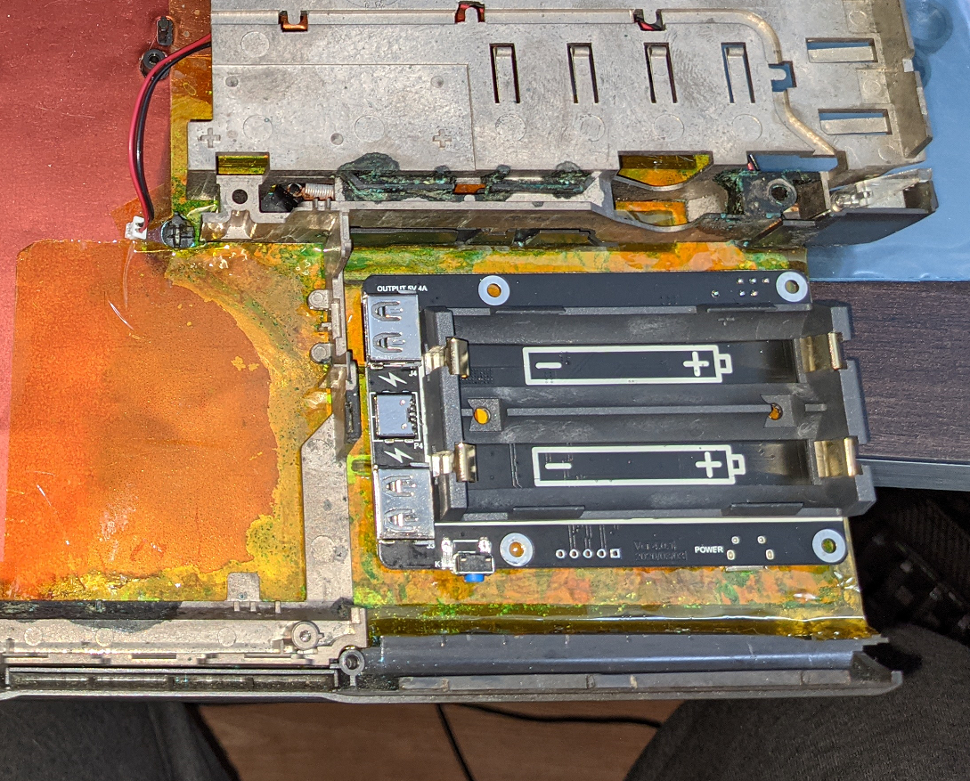
Looking around online, I ran across this design: amazon.com/gp/product/B082CVWH3R . A three amp output should have enough headroom for the Pi 4, the screen, and some peripherals. Hopefully it performs well. I also hope those used batteries are up to the task, but if not, I should have some new ones somewhere in the parts heap. At least the board fits into the case well.

It occupies a fair amount less space than the original battery pack. I haven't decided how I'm going to integrate the power button and battery state outputs into the design, but one thing at a time. I'm also not using the pogo pins intended for attaching directly to the Pi, so it needs some decent standoffs (probably a 3D printed frame) to keep them floating above the bottom of the case. I've covered the battery area with kapton tape to reduce the possibility of shorts, and because battery leakage abatement is an endless fight that I'm choosing to literally gloss over for now.
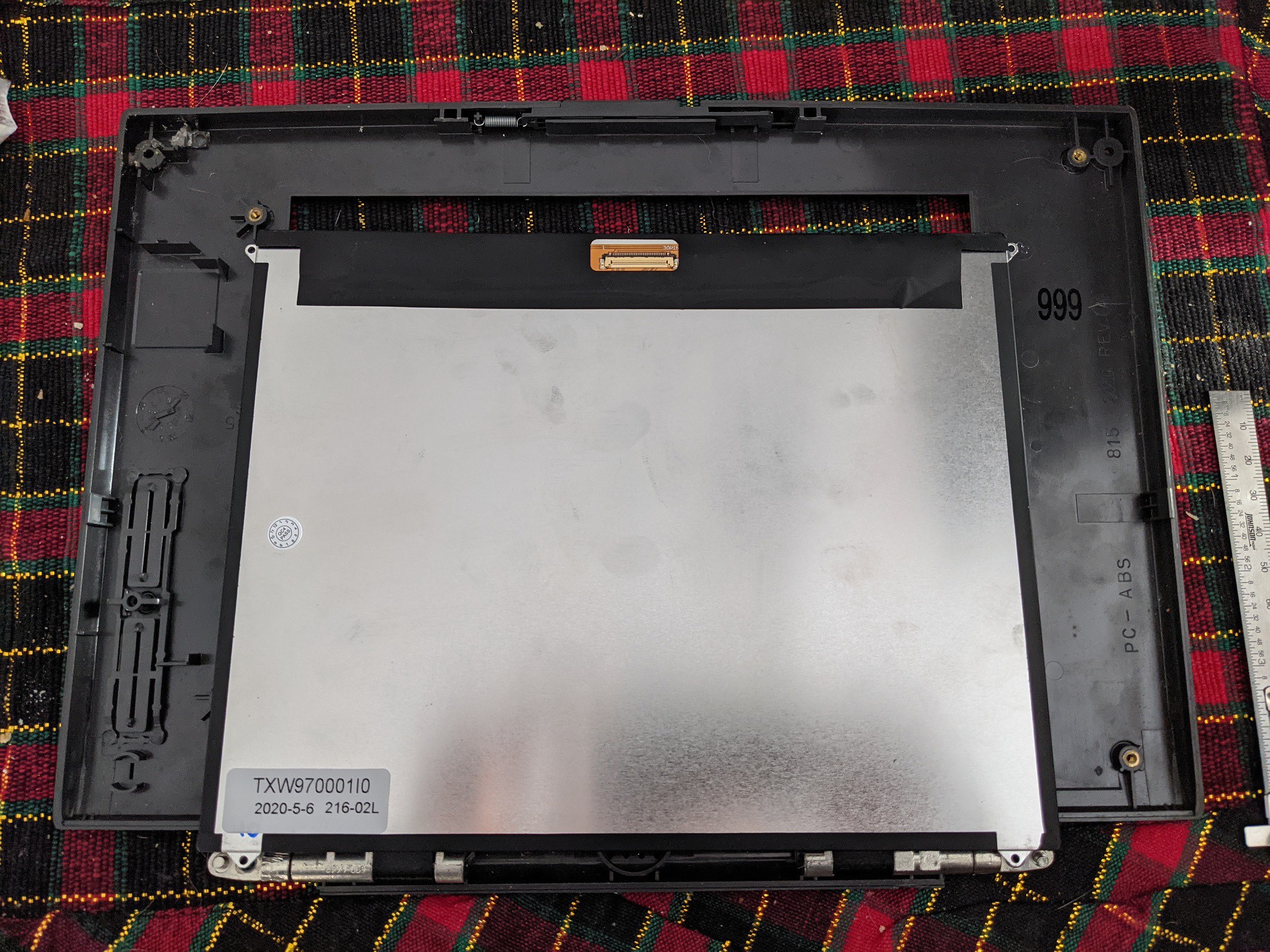
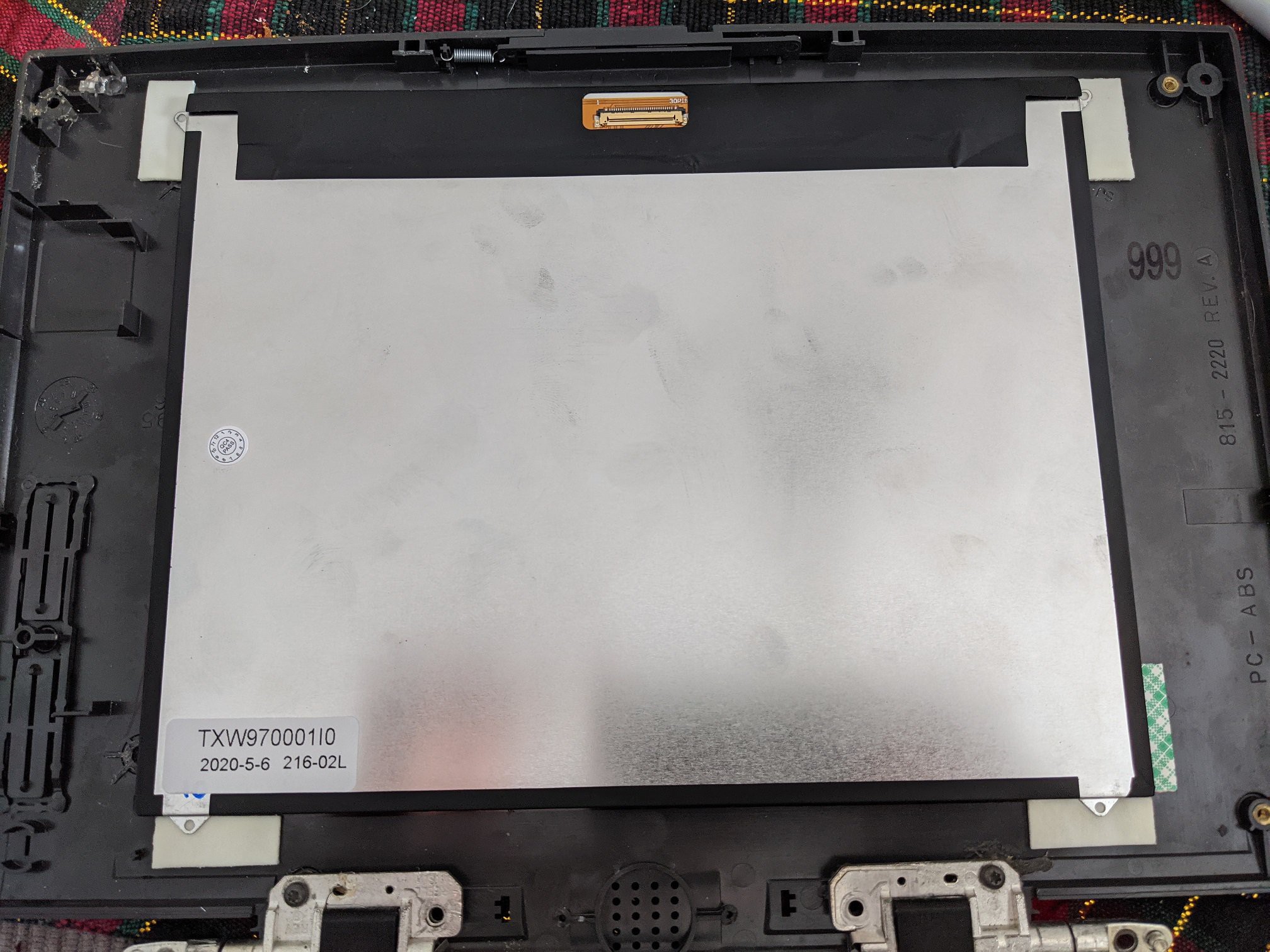
The inside of the case is still pretty ugly, but there's only so much I can do about that. It should be covered before too long anyways!
-
A Little Display Progress
01/01/2021 at 21:33 • 0 commentsAfter a months long hiatus to take care of more pressing matters, I finally have some time to spend on lower priority projects. Adafruit's Black Friday / Cyber Monday sale made the Pimaroni display I had been looking at a bit more affordable, so I picked one up right away.
As previously mentioned, the Pimaroni 10" display is slightly larger than the bezel space for the original display (9.5"). That being said, the picture on the Pimaroni display doesn't go all the way to the edge, so I can probably install it in the existing space without losing much. The bigger problem is fitting it around the existing mount holes.
On the left side of the picture, which is actually the right side of the display, the mount points for the old display are in the way for centering the new one. If I were trying to do a non-destructive mod, this would be a problem, but since I'm never putting the old display back in it's a little easier to deal with. An X-Acto knife makes short work of the fairly brittle old plastic, then a pliers to tease out the heat press inserts leaves me with a relatively smooth surface.
Now to mount the display. I had toyed with the idea of 3D printing some angle brackets to go on the corners under the mounting tabs. They would need to be a couple of millimeters thick to get the right stand-off distance from the bezel. However, that would still require adhesive in addition to the printed parts. Then I remembered I have a bunch of Scotch mounting squares on my desk. They're about the right thickness, won't be bothered by a slightly irregular surface, and quite sticky.
I traced the bezel and cut out a paper template to tape to the front of the display so I could get the portion I wanted visible properly centered in the space. Then I traced the display in sharpie, took it off the bezel, and placed pieces of mounting square under where the tabs go.
Effective, if low tech. A second layer of mounting square on top of the existing one sandwiches the tabs between layers of adhesive. They're not going to be able to move any time soon. As long as the squares stay attached to the bezel, we're in business. An added benefit of course is if I need to take the display out for any reason, it will be relatively easy and only require me to replace a few cents worth of readily available adhesive.
I now have what is basically a strange looking monitor with no stand. Progress!
-
Parts and Parts
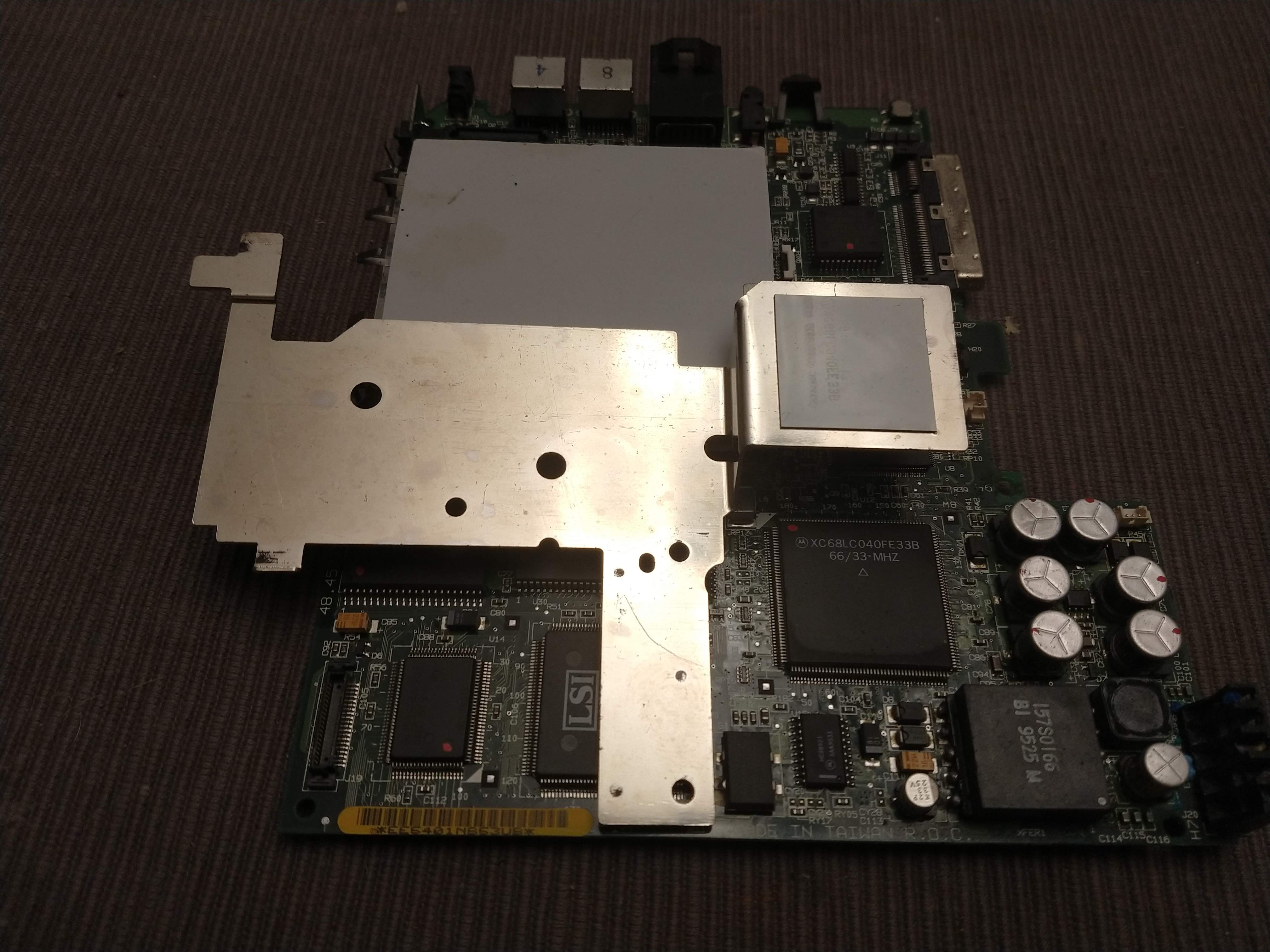
07/21/2020 at 21:21 • 0 commentsSince I have the case mostly repaired, and the keyboard works I can start selecting the other parts to go into the system. If the keyboard had been a loss this would be complicated by having to find one that would fit ok into the case, but as it is I'm now mostly dealing with functional parts that won't be seen. The most notable exception here is the display.
The Powerbook 190 came with a 9.5 inch, passive matrix, greyscale display. I'm not even entertaining the possibility of using that. The 190cs came with a generous 10.4 inch color display. Maybe I should have started with one of those, but hey, the price on this one was right. Some cursory searches haven't come up with anything the right size to fit my 190 bezel, but there are options in the 10 inch range. That's only a half inch difference, and depending on the display I might not miss much. But if I need to widen the opening in the bezel, that's not the end of the world.
Currently I'm considering the Pimoroni HDMI 10" IPS LCD Screen Kit. I will admit the price is a bit high for a project like this, but the size is right(ish), the resolution is decent, and -this is key- it's the right aspect ratio. 10.1 inch displays are all over the Internet, but 10 inch displays with a 4:3 aspect ratio are not, and that's what's needed here. Plus, the Powerbook has those fancy display control buttons right on the bezel, which I can re-purpose for the Pimoroni display's menu buttons. The board it comes with won't have them in the right place, but that's easy enough to deal with. OSH Park will already be making some boards for me. What's one more?
---------- more ----------Besides the display, I will have to work out input devices, external ports, and cooling. There is the matter of a battery for portability, but I'm saving that for later.
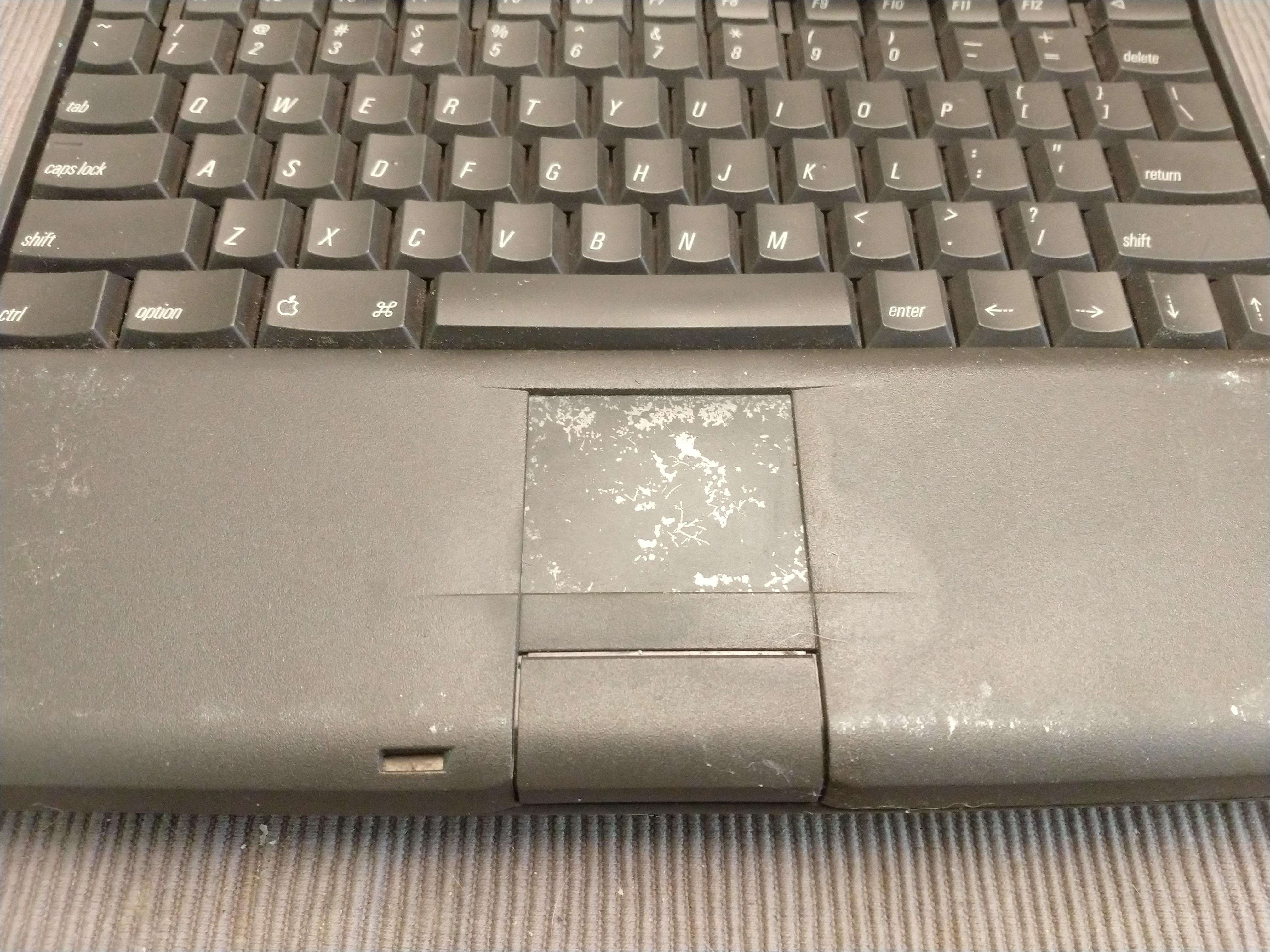
For input devices I have the original keyboard with Teensy controller, and a trackpad. The original trackpad is worn out, and the underside is a corroded mess.
I need something that can interface over USB anyways, so the original needs to go. Fortunately finding one that would fit in with the aesthetic of my Powerbook was relatively easy. I picked up a Perixx Peripad 501, used, that appears will fit ok under the palm rest once it's out of its case. Not all of the touch surface will be exposed, but that shouldn't matter. Hooking left and right click to the original left click only button will take some work, but should be doable. I may just have to replace the original exposed assembly with something custom. 3D printing is going to be key for a lot of what I'm doing on this project.
For those playing the home game, you'll note that makes two USB 2.0 devices to connect to my Pi 4. That's fine, the Pi can support that, but what if I want to reserve one for an external port? Sounds like we're going to need a hub. I've taken small hubs out of their cases for projects in the past, but space is going to be more limited in this build. I'm going to want a dedicated solution. I already know I'm going to need a board to hold FFC connectors and debounce circuits for the keyboard controller. It's not that big a deal to include a USB hub IC with associated passives. Naturally there are a lot of options here, but right now I'm planning on using a USB2422 from Microchip. It appears to be relatively easy to design around.
One of the USB 3.0 ports will be connected to an SSD using a SATA adapter. With the USB 2.0 hub, this will leave one of each type to extend to the case as external ports. With all the connections coming off it, the Pi will likely end up looking like an octopus orchestrating the functions of the laptop from its lair beneath the keyboard. That being said, extending all the connections from the Pi makes the layout more flexible and the Pi easily replaceable (upgradeable).
The Pi will also need a reasonably robust cooling system, unlike what the original processor had.
A steel plate won't quite do it for a Raspberry Pi 4. I can get a good heatsink for it, but being closed inside a larger case, it may require some active cooling. Looking around online, there are a number of low profile squirrel cage fans available that run on five volt DC. This should be a good option, but I will have to work out the airflow in and out of the case. Since the original electronics didn't need a fan, the case doesn't have the fan grills we're used to seeing on most modern laptops. This can, of course, be worked out. There are open spaces on both sides of the case where the floppy drive and PCMCIA slots were.
That'll do it for now. I need to do some work in KiCad.
-
Bring on the Breadboard
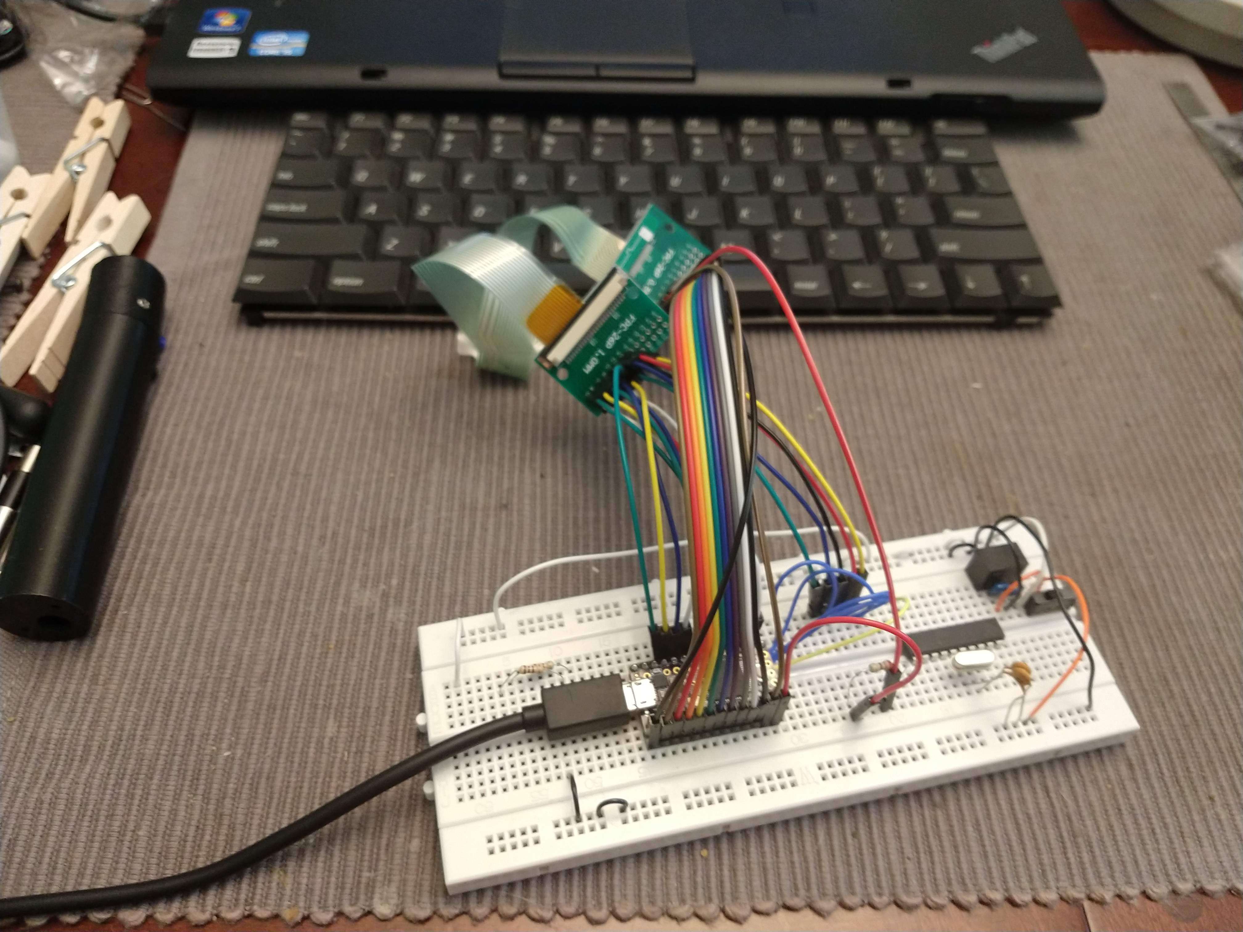
07/10/2020 at 21:21 • 0 commentsI don't have a lot of experience with Arduino. Most of my embedded work has been with AVR microcontrollers in C. So imagine my surprise when I got the Arduino environment up on my system with the Teensy loader and found it has a dedicated preset for HID, including a keyboard. Once I brushed up on how matrices are handled, getting a rough working version was surprisingly easy.
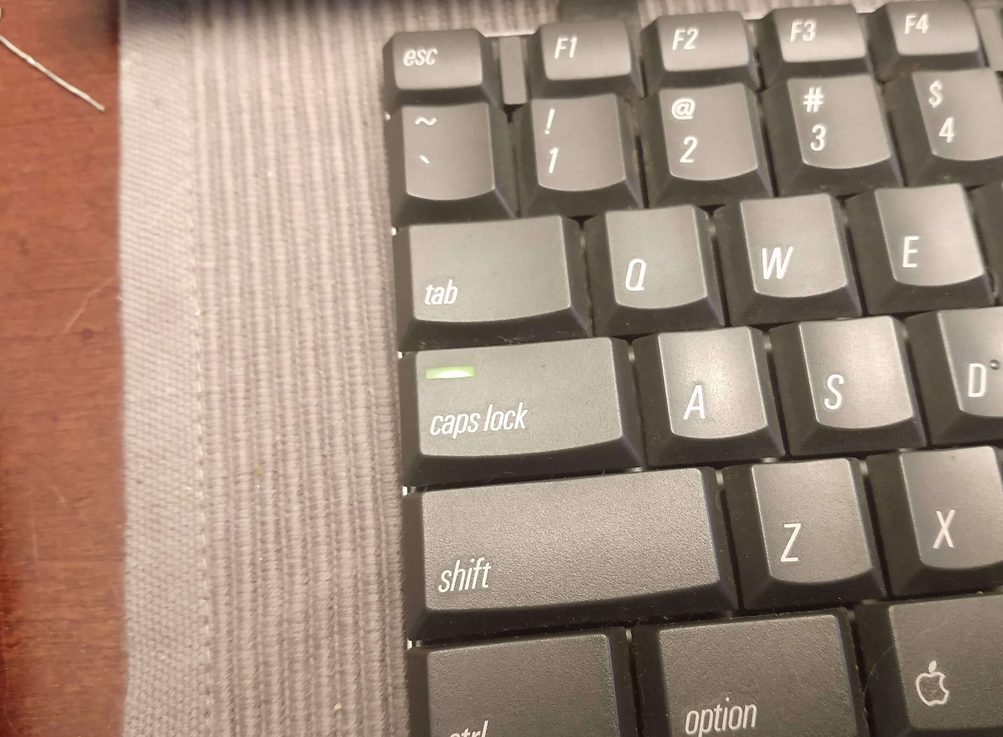
Ignore the ATTiny and associated parts. Every breadboard I own has a strata of different projects on it. The keyboard controller is an ugly pile of jumpers, but after a little bit of debugging every key works as expected. My lazy debounce routine needs work (will likely try out the Bounce library), and it currently only recognizes one modifier key at a time, but it functions. The proof of concept is good enough to start designing the carrier board in KiCad. The Caps Lock LED even still works!
That's enough keyboard talk for now. Time to move on to more fun things, like parts selection.
-
Making it Virtual
07/06/2020 at 00:17 • 0 commentsThe keyboard went back together better then I expected. All the keys still work (for now), so it was time to finish the documentation so a working controller can be programmed. I picked up a couple OSH Park edition Teensy 3.2s with a board order a while back. I figured I'd have a use for them eventually. From what I can tell, it's one of the chosen platforms for custom keyboards, so this should be easy, right?
I started looking into what it takes to load up a custom configuration of QMK and was immediately confused. Maybe it's just me, but it seems it's pretty easy to get working on a supported (or community supported) keyboard, but way less straightforward on an arbitrary layout. First things first though. I needed to model the keyboard. The physical layout was relatively easy to reproduce on keyboard-layout-editor.com.
The keys are updated a bit to fit the current decade. Option is now Alt, and Command is listed as Win - more generically known as the GUI key. Delete and Backspace were flipped compared to current keyboards, so I changed it to match in this layout. Return and Enter will both be mapped to Enter in the programming, although the position of Enter is a bit archaic and I may map it to something else eventually. However, I first need to work out the wiring.
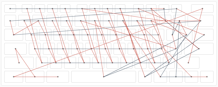
I imported the layout into Keyboard Firmware Builder (kbfirmware.com) to see what it would give me. With the wiring reproduced virtually, here's what we get:
Pretty, isn't it? I understand why some of the decisions were made. An old membrane keyboard doesn't exactly include diodes, so the layout is intended to reduce ghosting. Of course that means the layout in QMK will have to be fully customized, a task I have had a hard time finding information about. QMK appears to be very powerful, but for someone new to the scene, the learning curve seems steep, and I haven't been able to find a good walkthrough.
After a bunch of digging, I think QMK sounds great in theory, but it's kind of a lot. I appreciate the support it provides to the custom keyboard community, but it seems needlessly complicated for my purposes. I've done some embedded programming, and think I can do the same thing, but much simpler. This whole project was supposed to be a learning experience, right?
-
Draw on the Traces
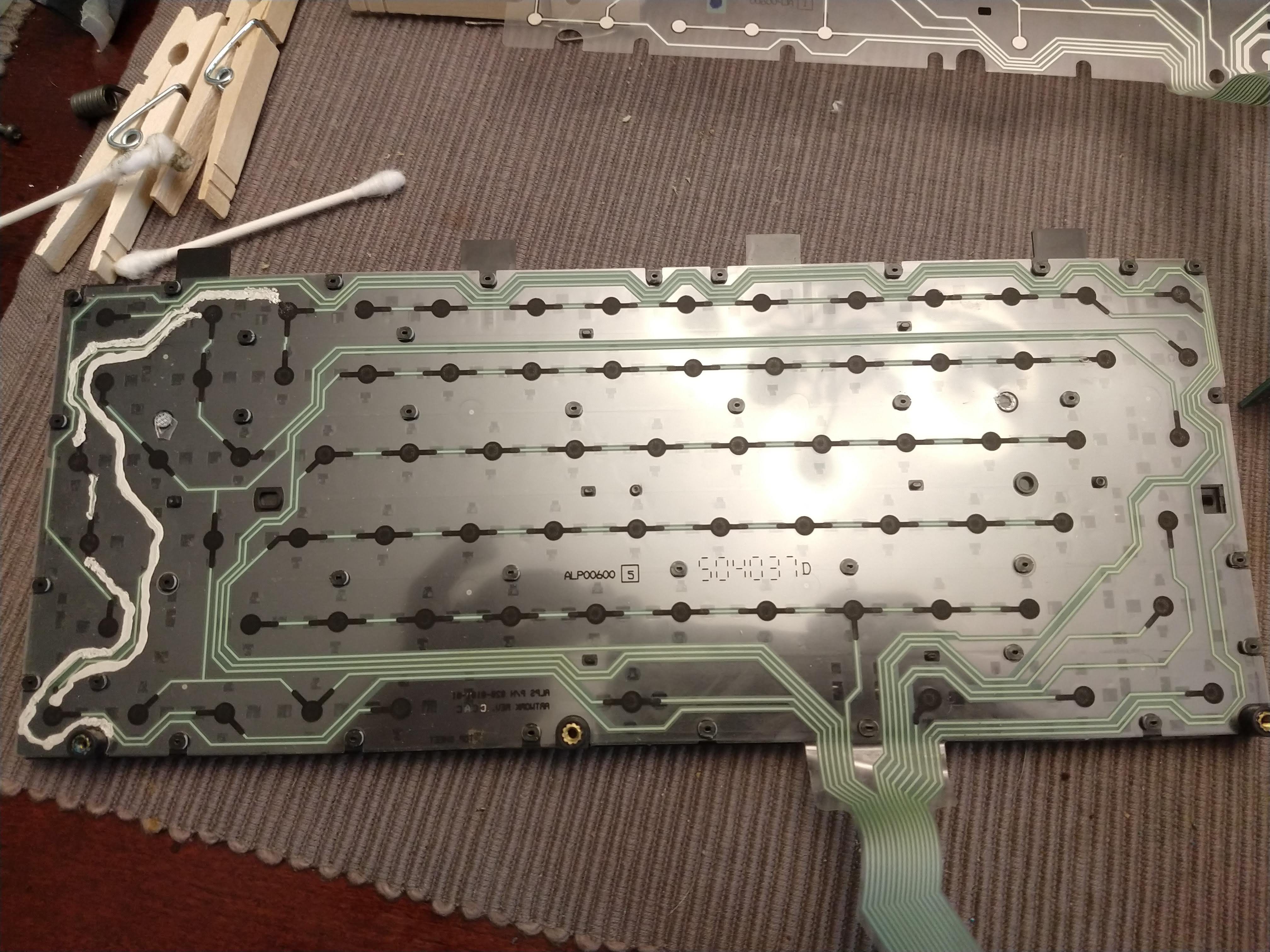
06/30/2020 at 19:56 • 0 commentsI'm no chemist, but it seems somehow the battery leakage affected the conductivity of some of the traces in the keyboard. Thankfully it was only a problem above the battery compartment, otherwise I would be better off finding a different keyboard that would fit. To fix the traces I had to take the keyboard down the rest of the way, which required cutting the places the membranes were bonded together, but it turned out ok.
I am neither a surgeon nor an artist, and MG Chemicals' silver conductive pen isn't exactly a precision instrument, but the traces work now. That's all I'm looking for in this thing. None of it will be visible anyways, and if the keyboard fails down the line, I'll either repair it again or replace it finally. For now, I have all 76 keys mapped out and ready for the next step. I'll put the matrix spreadsheet up in the files section once it's formatted properly.
-
Case Layout Tetris
06/27/2020 at 18:36 • 0 commentsWhile I'm waiting to continue work on the keyboard, I may as well start thinking about how to lay out the internals.
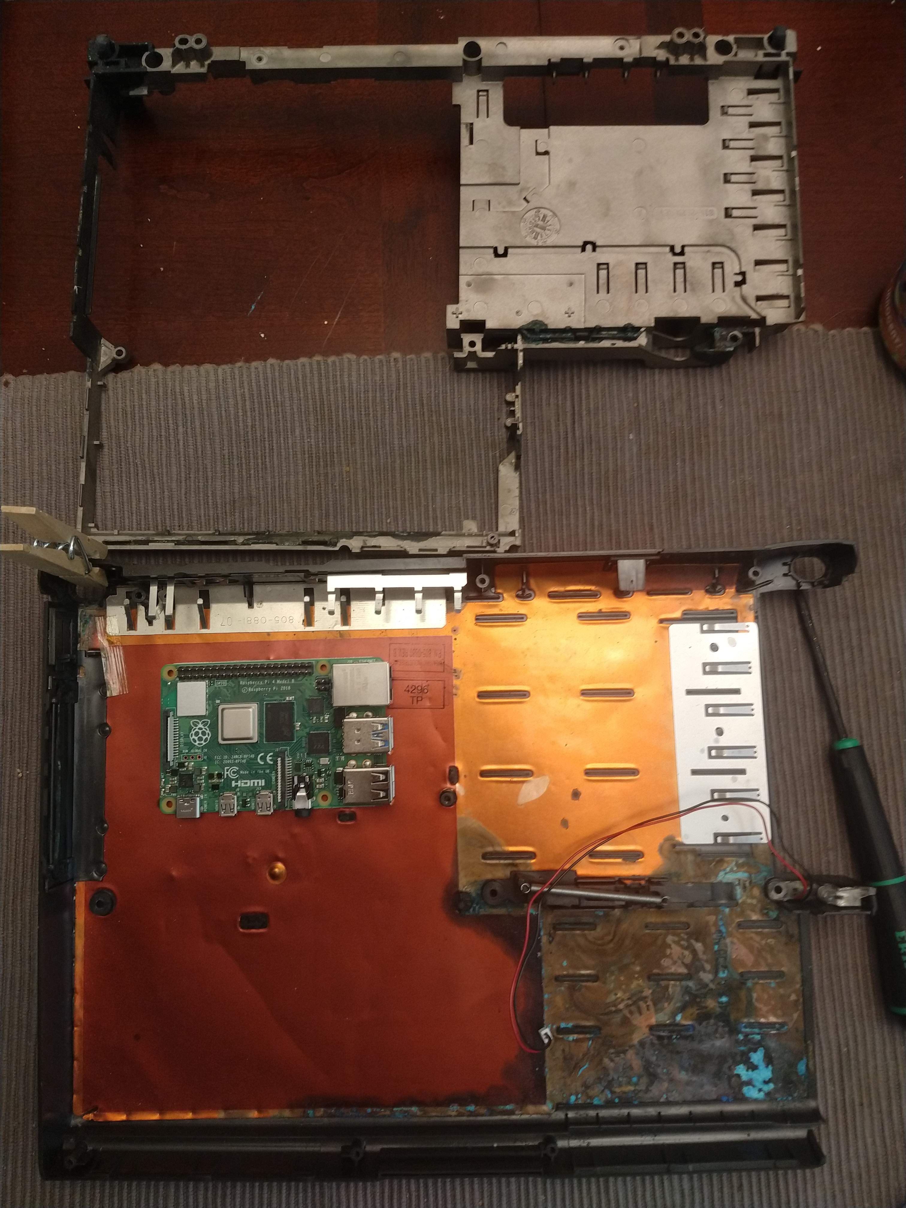
Obviously the Raspberry Pi 4 will take center stage, but it will have to share the case with all the support electronics: LCD driver, USB hub, SSD, keyboard controller, touchpad, and battery/charge controller. There will probably be more, especially if I can fit those parts in efficiently. To that end, I will probably roll my own support board with a USB hub IC, Teensy, and the necessary cable connectors. I'll have to decide if I want to keep the old floppy drive bay covered, or cut that portion out of the support frame.
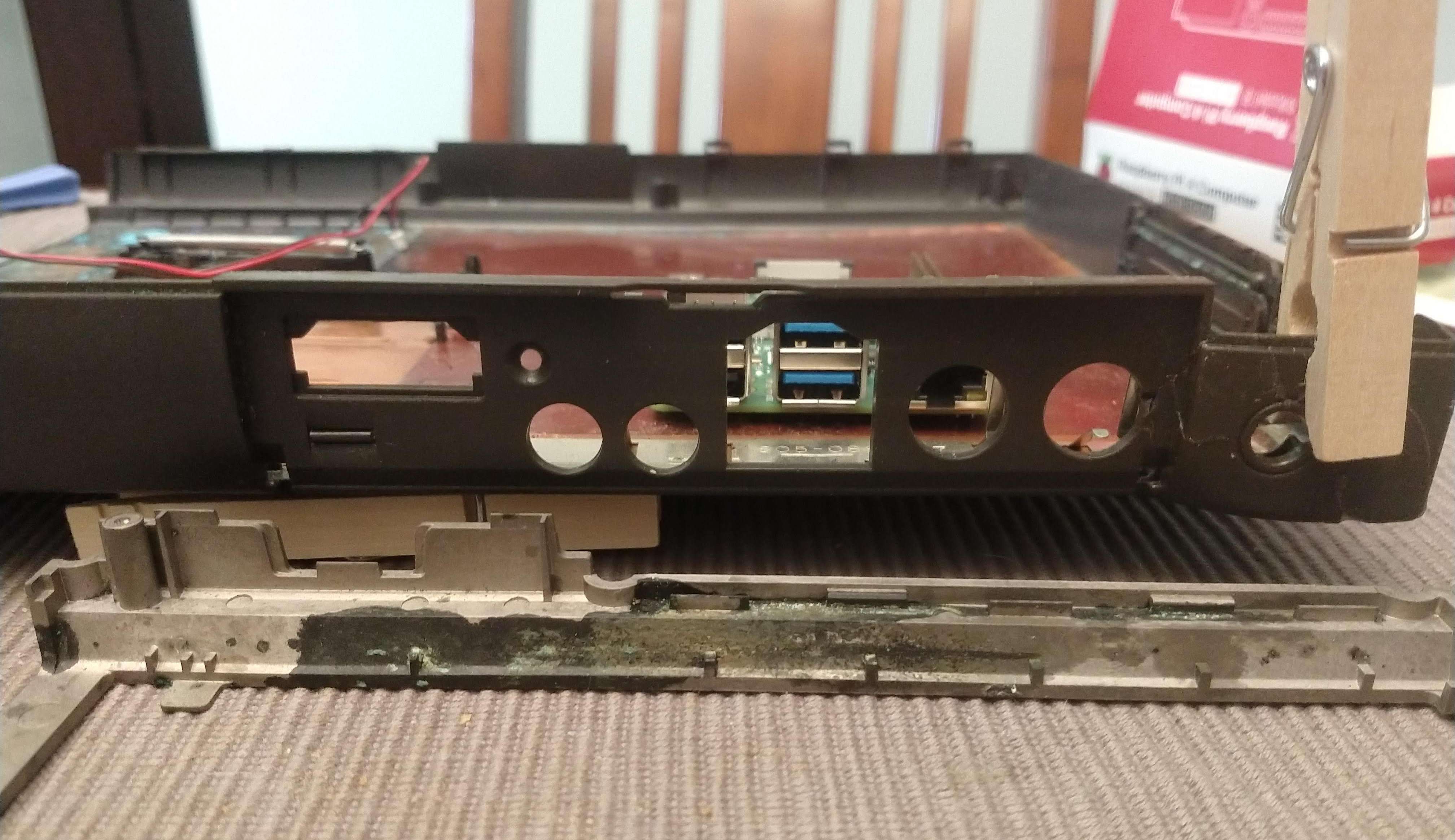
Because literally none of the external ports on the Powerbook 190 are still in use, with the exception of the barrel connector for power, I'll have to be creative fitting the Pi's connections into the existing holes. It'll probably end up looking like an octopus, with extension cables running to different places on the case. One USB 2.0 port will be reserved for connection to the input devices through the hub, and one USB 3.0 port will be connected to an SSD. Only one of each will be broken out as external connections, along with Ethernet and one HDMI port. I think a 3D printed cover plate will be called for here. Given the concave shape of the port area, a cover place could probably fit right on the outside and only expose the modern ports. This would remove a little of the retro appeal, but give it a much cleaner look.
As you can see, repairs on the case and removal of the battery leakage are ongoing, but it's getting there.
-
They Build Em Like They Used To
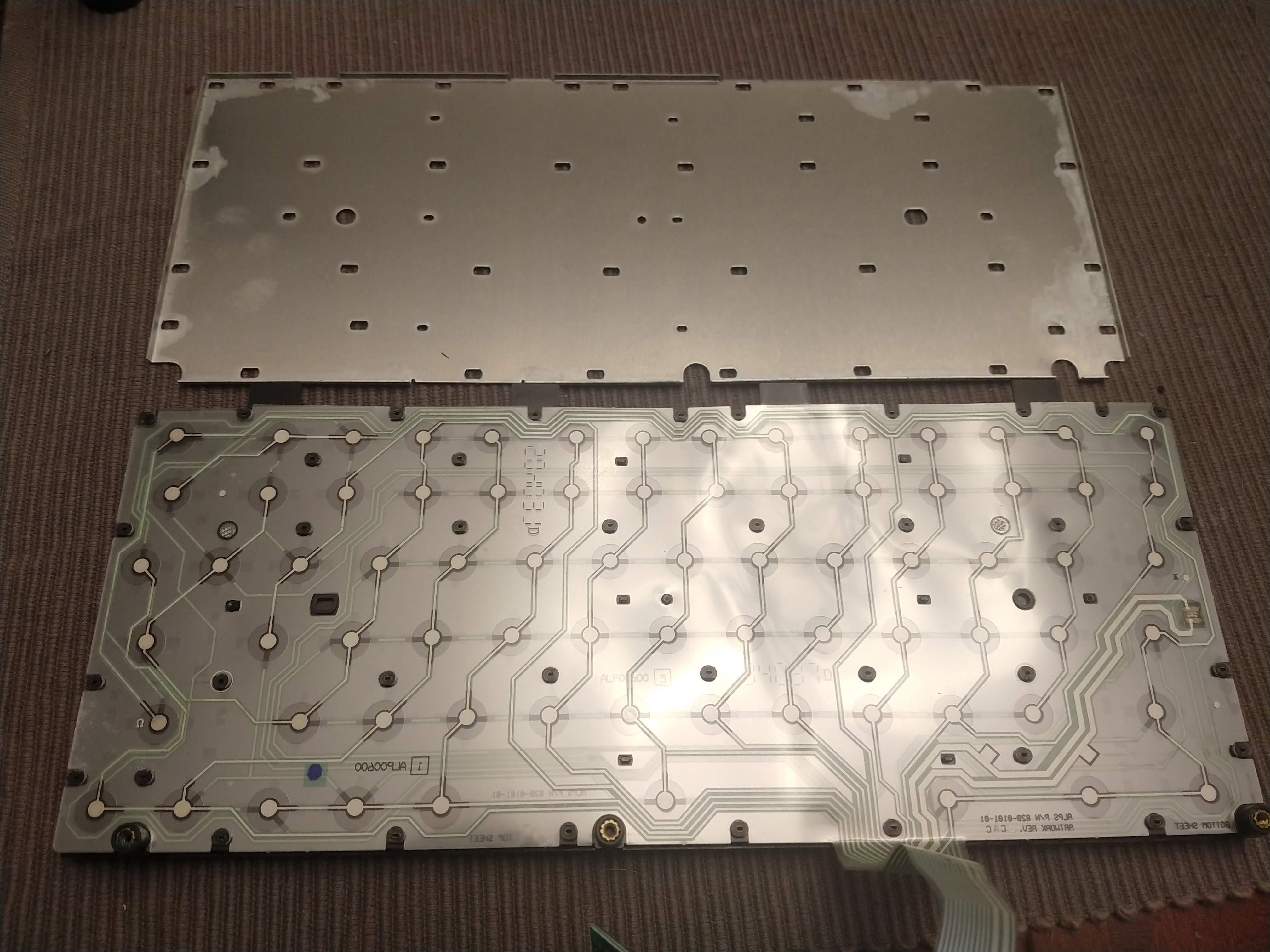
06/24/2020 at 22:20 • 0 commentsCutting away the bare minimum from each of the "plastic pop rivets" on the bottom of my Powerbook keyboard revealed the membranes nicely. It turns out the thick traces are indeed for the caps lock LED.
This is as far as I'm planning to take it down. It turns out 1995 Apple made working on this keyboard as hard as modern Apple would. In addition to the destructive removal of the aluminum plate, the membranes are bonded together in two places, so I'd have to cut that part to separate them fully. I hope that won't be necessary.
Some of the pads definitely suffered corrosion from the battery leaking in the case. Very careful application of alcohol cleaned them up ok, but the missing keys still didn't register. After some poking around the affected traces with a meter, it turns out I'm missing some of the matrix because the traces have become magically non-conductive in a couple places.
So how does one go about repairing that? Fortunately, while this is new territory for me, it's hardly a new issue. A quick search returned an eevblog conversation that recommends conductive ink. The good stuff from MG Chemicals isn't cheap, but I'd rather pay a bit more and have a better chance of success. Time to work on something else while Amazon does its thing.
-
Trying the Blue Pill First
06/24/2020 at 19:41 • 0 commentsNow that the obligatory Matrix reference is taken care of...
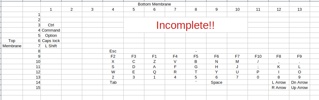
I figured I would see if the matrix on this keyboard could be brute forced without having to take it apart (blue pill). As it turns out, yes it can... to a point. Here's what I have so far:
A quick note on the pin numbers: The spreadsheet uses the numbers as I see them on the breakout boards. Since the membranes are face to face, one of them is technically upside down, making the pin numbering backwards. That's a problem for another day.
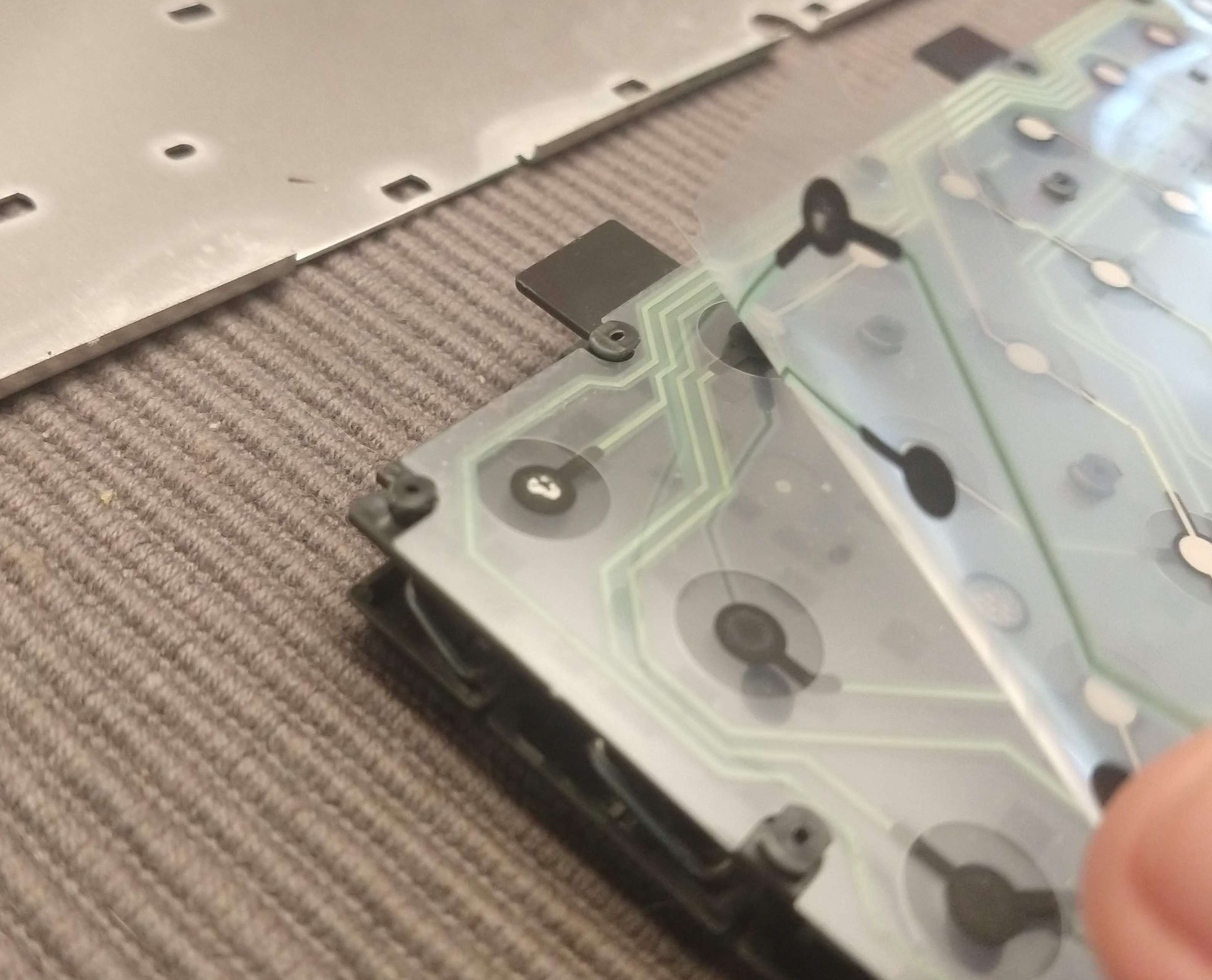
The matrix is reasonably logical. I believe pins two and three on the bottom membrane are power and ground for the caps lock LED, but haven't tested that yet. As you can see, I'm missing a few keys still. After going over the potential combinations multiple times (including the supposed LED pins), I still haven't found tilde, F11, F12, enter, return, delete, backspace, R shift, either bracket, pipe, or +/=. Obviously that's a bit of a problem. It's easy enough looking at the spreadsheet to extrapolate where they probably are, but testing hasn't produced those results. Maybe the contacts are dirty or corroded. It would hardly be surprising given the amount of battery leakage on everything. Unfortunately finding out will require taking the keyboard apart, with putting it back together being the harder task given how it's constructed.
The plastic frame is held onto the aluminum base with dozens of plastic studs. Each stud is melted and spread out to form what is essentially a plastic pop rivet. That's all fine and good if you don't need to re-open the finished product, but a bit problematic for re-usability otherwise. I don't see a way around that, however, since I'm missing a bunch of keys from my matrix. It looks like my favorite plastic bonder is going to get some more use.
Raspberry Pi Powerbook
Replacing the guts of a broken Powerbook with everyone's favorite SBC