-
FDA Product Code, 510(k), Medical Device Standards/Regulations
10/08/2020 at 16:40 • 0 commentsChris Justice of Engenious Design, a medical product development firm, recently volunteered some valuable insight into the FDA approval process for medical devices in the United States. While the OpenFluidWarmer project is unlikely to pursue FDA approval because of how expensive the process is, it is a goal of this project to meet as many FDA approval requirements as possible.
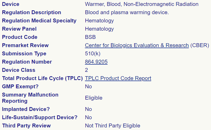
A good first step of understanding the FDA approval process is to identify the product code for the type of medical device being evaluated. This search is done through the FDA Product Code Classification Database. For IV fluid warmer designs like the OpenFluidWarmer that to not use electromagnetic radiation (radio waves or microwaves) to warm the IV fluid, the product code is BSB. We also learn that device class is II and submission type is 510(k) for BSB medical devices. The image below is the database search result.
In addition, with knowledge of the product code, we can look up the competitor BSB devices that have already received FDA approval.
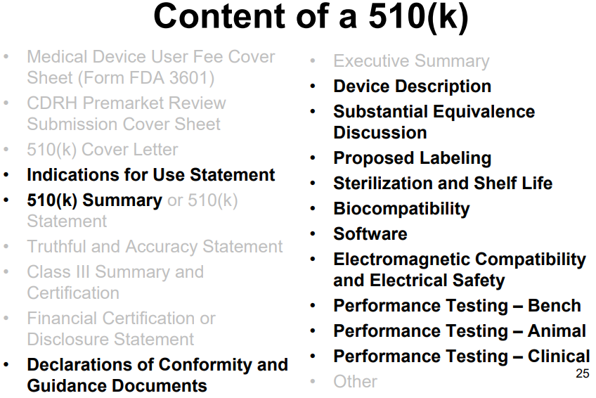
"A 510(k) is a premarket submission made to FDA to demonstrate that the device to be marketed is as safe and effective, that is, substantially equivalent, to a [existing] legally marketed device." The content of a 510(k) submission is summarized in the image below. More information on the premarket notification 510(k) program can be found here and here.
The following standards/regulations also apply to the OpenFluidWarmer device:
- IEC 60601 design standard - "a series of technical standards for the safety and essential performance of medical electrical equipment"
- 21 CFR 820 US FDA quality management regulations - "requirements in this part govern the methods used in, and the facilities and controls used for, the design, manufacture, packaging, labeling, storage, installation, and servicing of all finished devices intended for human use."
- ISO 13485 international quality management regulations, "specifies requirements for a quality management system where an organization needs to demonstrate its ability to provide medical devices and related services that consistently meet customer and applicable regulatory requirements."
More work is required to fully understand all the implications of everything discussed in this log on the final OpenFluidWarmer design, but I see just having a clear understanding of what medical device standards and regulations to follow as a big step forward.
-
Fail Better With Sous Vide
10/07/2020 at 20:41 • 0 commentsTesting this afternoon with a sous vide cooker shows a more promising path forward than the two hot plate design that has been in development for the last three months.
![]()
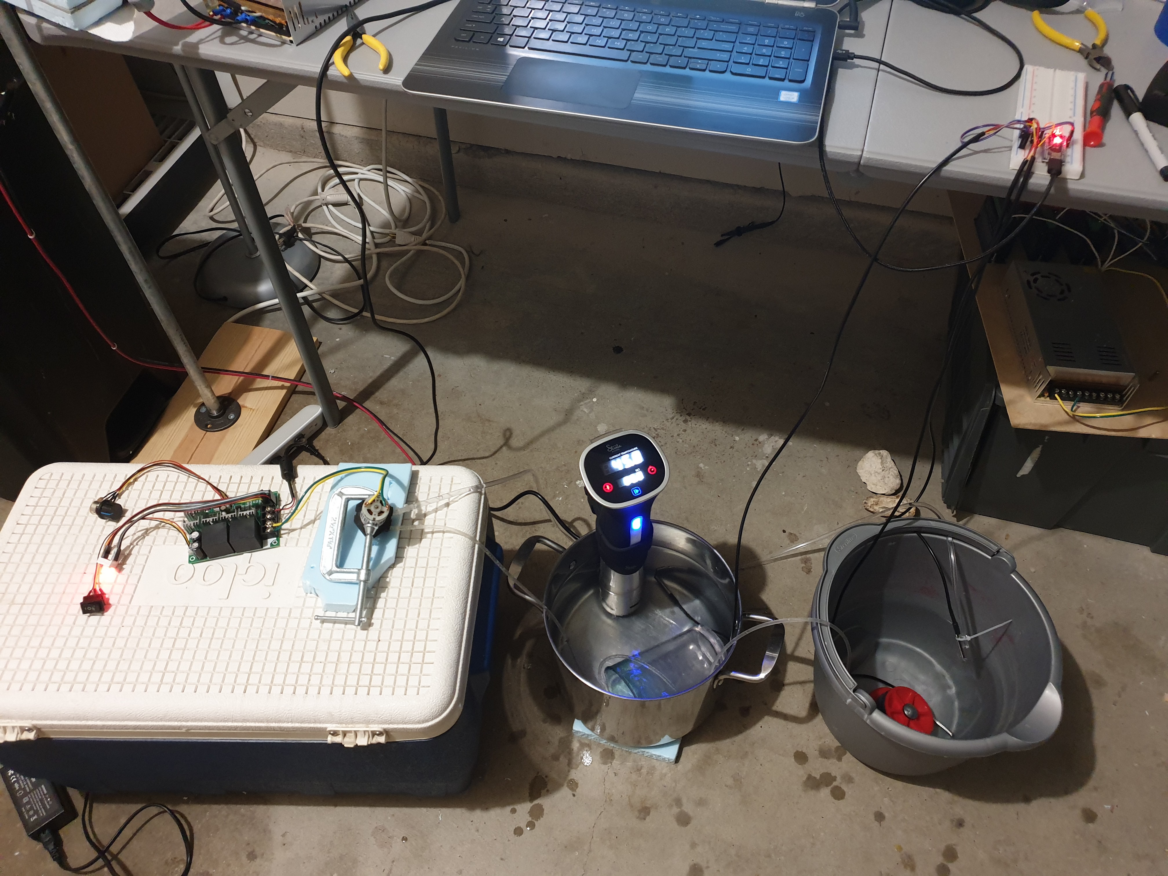
The sous vide cooker (center of image with lit display) maintains the water bath at a constant temperature. The set point temperature is selectable by the user. In the water bath I submerged 660mm of IV tubing. 660mm is the same length of IV tubing used by the two hot plate prototype. Then the peristaltic pump pulls water from the far right bucket, through the IV tubing in the temperature bath, and back to the bucket. There is temperature sense in the water bath, in the bucket, and at the IV tube outlet.
Results from today's testing show that this technique can warm the fluid flowing in the IV tube from 4°C to 38°C at 20mL/min with the water bath at a 70°C set point. The two hot plate design could only warm fluid from 4°C to 24°C at 20mL/min with a 105°C heater set point. Using the same length of IV tubing, the sous vide method uses a 35°C lower set point and achieves a 14°C higher temperature rise!
It accomplishes this through a higher rate of heat transfer between the heating elements and the IV fluid. As a liquid, water achieves maximum contact with the outside surface of the IV tubing. More contact area -> lower thermal resistance. The sous vide cooker has a agitator that circulates water through the heating elements and mixes up the water in the bath. Mixing the water ensures that the water that rejected heat to the IV fluid is continuously replaced by warmer water. Higher flow rate across outside of IV tubing -> higher temperature at the outside surface of the IV tubing. Both the lower thermal resistance and higher temperature differential results in a higher rate of heat transfer to the IV fluid.
While I have not yet fully vetted the sous vide design solution, there are a few additional benefits that are clear already. The first and most important is that the sous vide method has the potential to cost less in materials than the two hot plate design. It packages a heating element, adjustable temperature control, a motor, and temperature display in a water resistant, easy-to-clean enclosure for under $50. That's about 4X more functionality than the two hot plate design and at a lower price point. In addition, the adjustable temperature control provides opportunity for the user to better tune the set point to match the IV fluid flow rate that is being used.
The sous vide method is certainly promising, but it does not have all the safety features that are going to be required to use a device like this in a medical setting. I already have an idea of what is required to "hack" sous vide cookers for safe IV fluid warming and will flesh out these ideas in the next few project logs.
-
Post Prelim Design Review Updates
10/07/2020 at 04:18 • 0 commentsThe preliminary design review was very productive. In all, three mechanical engineers and one electrical engineer were in attendance.
A big focus of the design review discussion was on how to significantly improve (i.e. reduce thermal resistance of) the heat transfer interface between the silicone heaters and the IV fluid. The thermal performance design requirement for the OpenFluidWarmer device is to warm 4°C fluid to 38°C at 20mL/min flow rate. Based on testing, the current prototype design can only warm the fluid from 4°C to 24°C at 20mL/min. A lower thermal network between the heaters and IV fluid is required to close that 14°C gap. There are three approaches that have the potential to reduce the thermal resistance and still satisfy the cost target for this device:
1. increase the length of tubing that is in contact with the hot plates. Heater set point and contact area staying the same, it could likely take just as much if not more tubing length to close the 14°C gap to 38°C than it does to achieve the 20°C temperature rise from 4°C to 24°C. The reason is Netwon's Law of Cooling -> the rate of heat transfer between two bodies is proportional to the temperature difference between them. The closer the fluid temperature is to the heater set point the longer the tube must be to achieve each successive 1°C fluid temperature rise because the reduced rate of heat transfer. At the same time, the heater set point is 105 degC; far from the 38°C target outlet temperature. An extra 150mm tube length (20% increase) in contact with the hot plates may result in something close to an additional 5°C temperature rise.
A couple other factors at play here are the maximum length of IV tubing that can be used by the device without requiring an IV tubing extension (a cost add) and the minimum allowable bending radius of the IV tubing before it kinks. It is not well known what the acceptable length of IV tubing can be used by the device. Obviously, if it uses up too much of the IV tubing, the IV tubing will not be able to reach the patient. More research and feedback from potential users is required here. IV tubing can be made out of different types of materials. In general, the cheaper IV tubing option is more likely to be the less flexible and more prone to kinking. More research is required to identify the IV tubing option most likely to be used by users in medical settings with few resources and determine the minimum allowable bending radius of that tubing.
2. increase the surface area contact between the IV tubing and hot plates per unit length of the IV tubing. The current prototype design sandwiches the IV tubing on two "sides" between the hot plates. So the thinking is that by better form fitting to the IV tubing outside surface, the thermal resistance contribution of the IV tubing can be reduced without increasing the length of tubing used by the device. Form fitting the IV tubing achieves more efficient heat transfer per unit length of IV tubing. Of the three approaches, this one arguably has the most potential for closing the 14°C gap. But it is dependent on finding a low-cost, thermally conductive, material that can form fit the IV tubing. Initial thoughts on this material are thermal gap pad, gel/gel-like material, or a fluid.
3. increase the heater temperature set point. The temperature rating of insulative materials currently used at the heaters is just above 100°C. So the 105°C heater set point being used is pushing the limit of the current materials. These insulation materials could be replaced with higher temperature rated materials and the heater set point increased. The increased heater set point would create a larger temperature differential between the heaters and the IV fluid and drive up rate of heat transfer. The only downside is that higher heater set points potentially result in increased risk of hemolysis. Though this risk has not been evaluated yet.
An interested test proposed during this meeting was to create a constant temperature bath using a sous vide cooker and perform several tests to identify what bath set point and submerged tubing length is required to achieve the 4°C to 36°C at 20mL/min performance target. This test serves as an ideal upper bounds to the thermal performance that can be achieved when warming IV fluids through standard IV tubing. There is nothing more form fitting than a fluid and the sous vide cooker has an agitator to achieve a decent fluid flow rate over the outside of the IV tube. The $50 sous vide cooker I ordered yesterday just arrived today. I plan to perform the testing sometime tomorrow.
-
Preliminary Design Review
10/02/2020 at 01:08 • 0 comments![]()
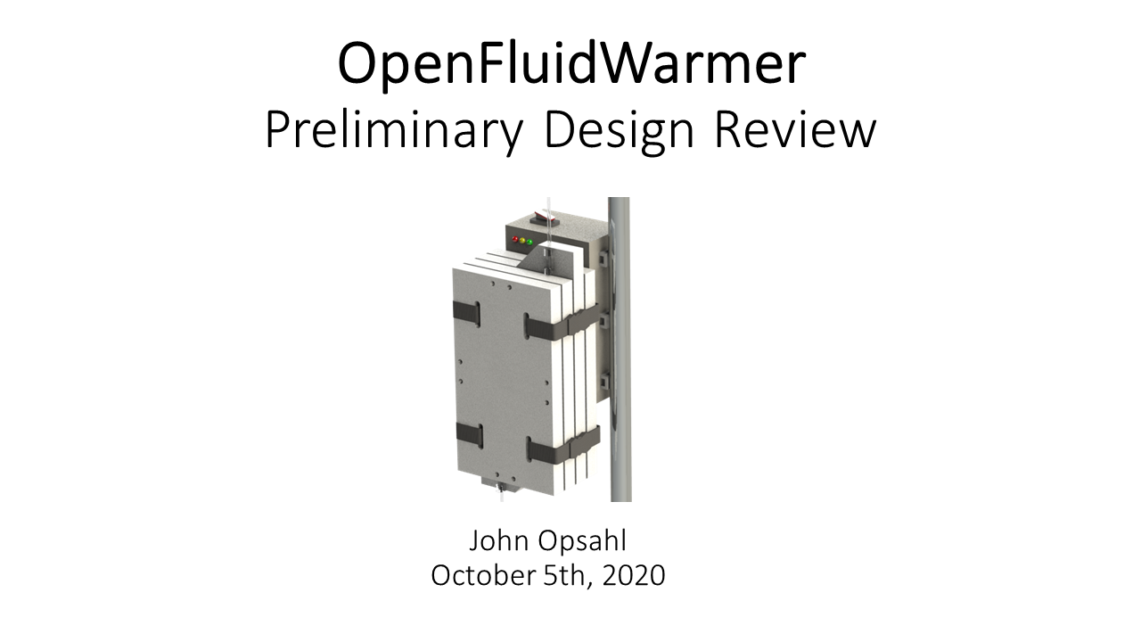
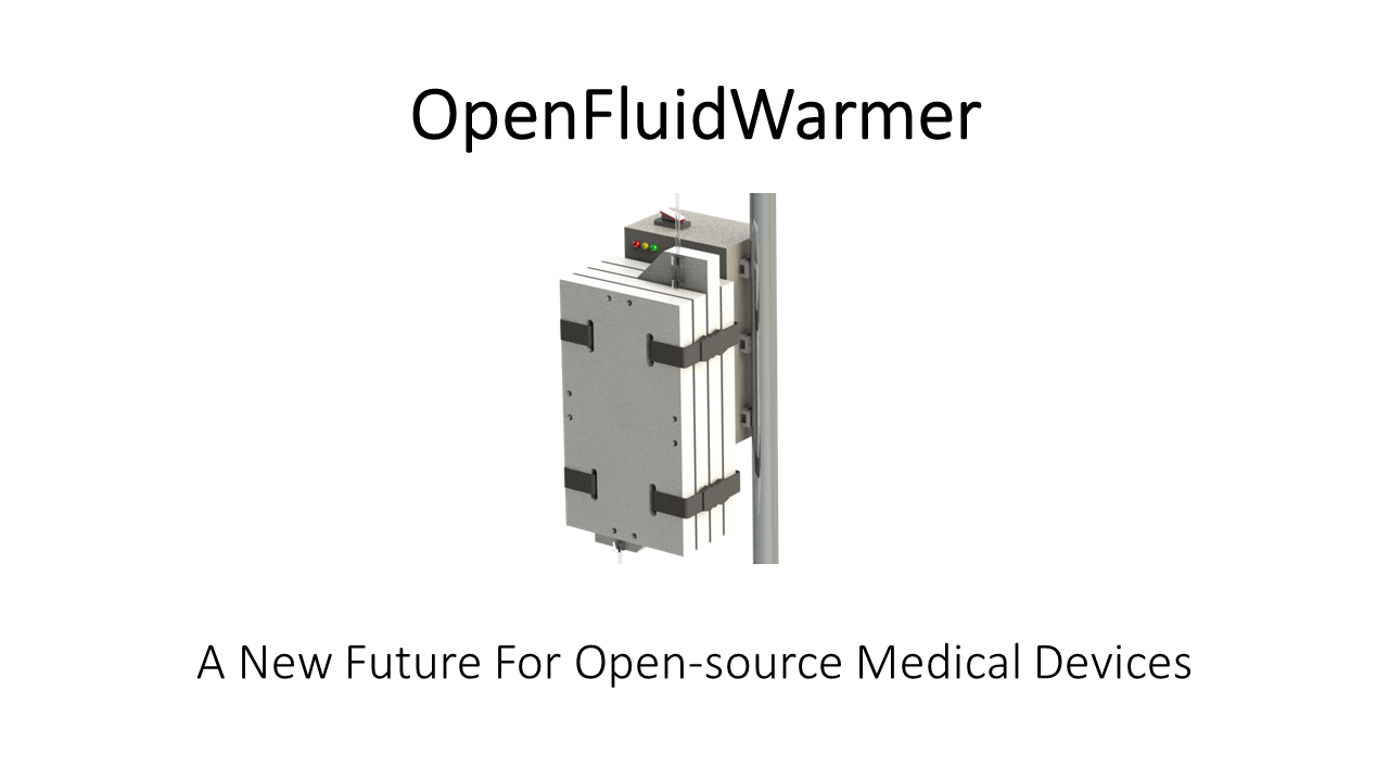
The preliminary design review for the OpenFluidWarmer will be held at 3pm CST on Monday, October 5th. See "OpenFluidWarmer_PrelimDesignReview" in the files section of this project for a copy of the presentation. All are welcome to attend and provide feedback.
Video conference access and any last minute changes will be communicated in the WeBuildBrazil "theopenfluidwarmer" Slack channel, https://webuildbrasil.slack.com/archives/C01BZR62N73
-
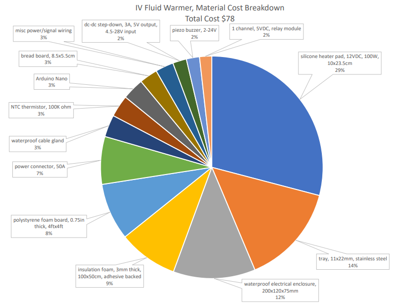
Material Cost per Unit, <$80 USD
10/01/2020 at 03:23 • 0 commentsThe latest workup estimates that the total material cost of one OpenFluidWarmer unit is just under $80 USD!
The five most expensive components being:
- heaters -> 29%
- stainless steel trays -> 14%
- electronics enclosure -> 12%
- adhesive backed foam -> 9%
- polystyrene foam -> 8%
As all items get accounted for and the prototype design is further refined, a small (<$10 USD) material cost increase is expected. Another cost increase (currently of unknown size) is expected when the design is updated to include all safety features.
-
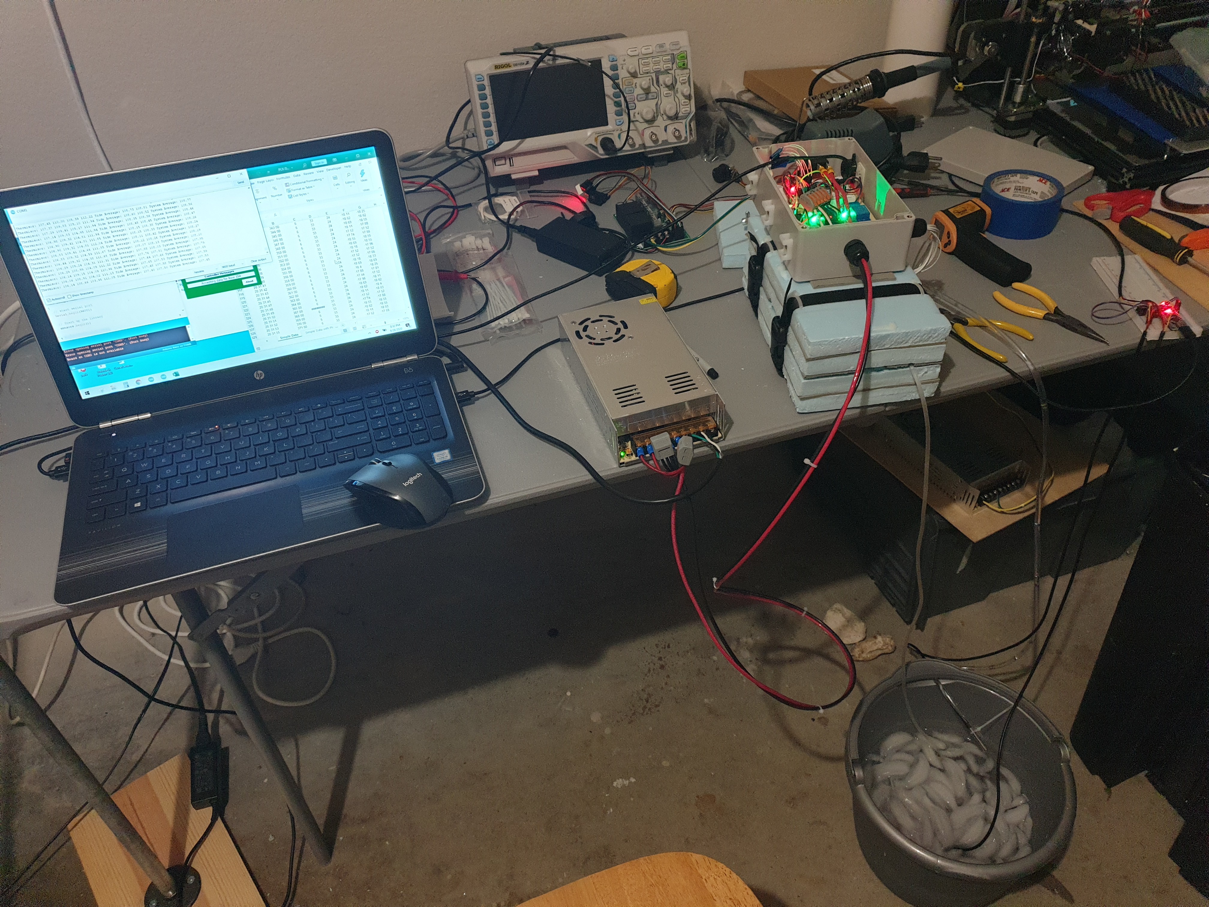
Two Hot Plate Prototype Thermal Specs
09/29/2020 at 03:11 • 0 comments![]()
The two hot plate prototype is showing promising fluid warming capabilities at the 20mL/min target flow rate!
For Test 1 and 2, I increased the heater set points until the outlet temperature was within +/- 2°C of 38°C human body temperature. I hit the functional limit of the heater setpoints during test 2 before outlet temperature was near the target.
Test 1, approx 20°C inlet temperature:
- fluid flow rate, 20mL/min
- inlet temperature, 19°C
- outlet temperature, 36.5°C
- total fluid temperature rise, 17.5°C
- heater-off set point, 105°C
- heater-on set point, 103.5°C
- max observed temperature, 112°C
- ambient temperature, 28°C
Test 2, approx 4°C inlet temperature:
- fluid flow rate, 20mL/min
- inlet temperature, 6°C
- outlet temperature, 26°C
- total fluid temperature rise, 20°C
- heater-off set point, 105°C
- heater-on set point, 103.5°C
- max observed temperature, 112°C
- ambient temperature, 24°C
Seeing that the device could not achieve an outlet temperature within +/- 2°C of 38°C. I decided to lower the flow rate to find how close I could get to 38°C outlet temperature. Lowest flow rate that the peristaltic pump can run at is 13mL/min. The 7mL/min drop in flow rate resulted in a 7.5°C greater temperature rise!
Test 3, approx 4°C inlet temperature:
- fluid flow rate, 13mL/min
- inlet temperature, 6°C
- outlet temperature, 33.5°C
- total fluid temperature rise, 27.5°C
- heater-off set point, 105°C
- heater-on set point, 103.5°C
- max observed temperature, 112°C
- ambient temperature, 24°C
Test 4 was run at 64mL/min flow rate to understand temperature rise at higher flow rates. It showed a 8°C temperature rise.
Test 4, approx 4°C inlet temperature:
- fluid flow rate, 64mL/min
- inlet temperature, 5.5°C
- outlet temperature, 13.5°C
- total fluid temperature rise, 8°C
- heater-off set point, 105°C
- heater-on set point, 103.5°C
- max observed temperature, 112°C
- ambient temperature, 24°C
All and all, I am very happy with what this first prototype was able to achieve. With more development of the heat transfer approach, this device has great potential at flow rates of 20mL/min and below.
-
Constructed Using Widely Available Fabrication Techniques
09/27/2020 at 00:20 • 0 comments![]()
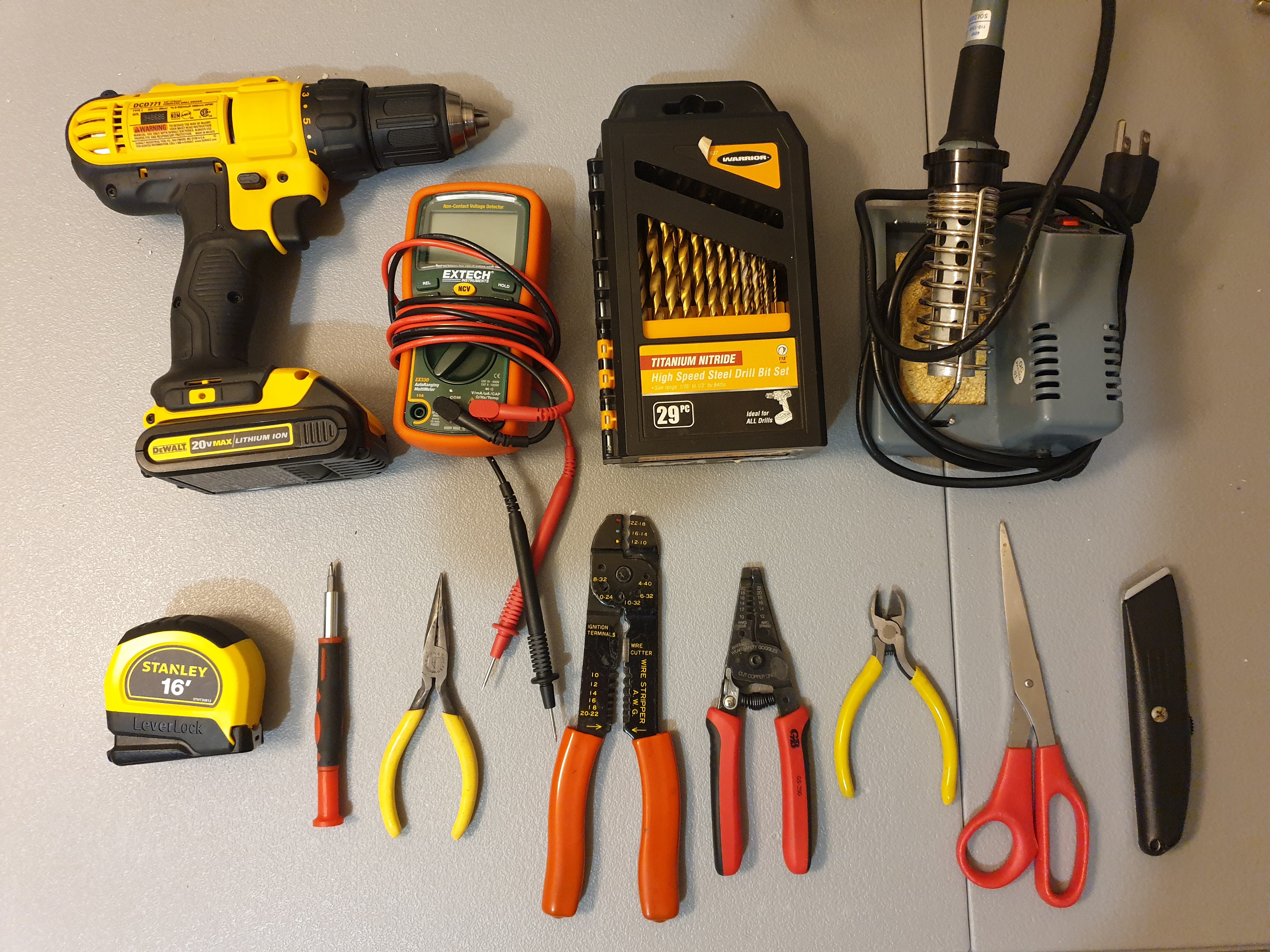
The image above details all the tools that were used to build the OpenFluidWarmer proof-of-concept prototype. I already had all of these tools in my toolbox. But if someone was on a tight budget and didn't already have the tools, they could get all the tools they needed for less than $200. Perhaps more important than how much they cost to buy is how readily available these tools are. Chances are that if you own a toolbox, you have at least five or six of these tools already. In addition, their wide availability makes it easy for someone unfamiliar with how to use one of these tools to either look up how to use it online or find someone locally that is familiar with how to use it.
Looking back now, I think there are opportunities to reduce the number and cost of tools required. It was convenient to use a electric drill and drill bits on some parts of the build, but I could just as well as bored holes in the insulation foam by plunging in a hot soldering iron tip or by rotating a screw driver.
Getting rid of the electric drill and switching to a butane soldering iron would remove the requirement for access to a wall outlet.
-
Prototype Heater Control Sketch
09/26/2020 at 01:59 • 0 commentsThe OpenFluidWarmer prototype Arduino sketch is detailed below. See the latest version of "OpenFluidWarmer_PrototypeSketch_MM-DD-YYYY.ino" in the files section of this project for the most up to date version of this code.
This sketch reads temperature from four thermistors (two per heater). Based on whether these temperature readings are above or below the hard coded temperature set points, the sketch will either send a command to the relays to close (and power the heaters) or do nothing.
// OpenFluidWarmer Prototype Sketch // Inputs: 2 thermistors per heater // Outputs: 1 relay per heater, indicator lights, buzzer #include <math.h> const int heater_pin[3] = {2, 3}; const int led_pin[4] = {4, 5, 6}; // red, yellow, green const int buzzer_pin = 7; const int thermistor_pin[5] = {A0, A1, A2, A3}; float thermistor[5]; // degC bool heater_state[3] = {false, false}; bool warmup_complete = false; const unsigned long led_blink_delay = 1000; unsigned long led_blink_time = led_blink_delay; const float heater_off_temp = 52.5; // degC const float heater_on_temp = 50.0; // degC const float V_0 = 5.0; // V const float R_2 = 100000; // Ohm // thermistor fit coefficients const float c1 = 0.8272069482e-3; const float c2 = 2.087897328e-4; const float c3 = 0.8062131944e-7; // averaging size int avg_size = 10; void setup() { Serial.begin(9600); pinMode(heater_pin[0], OUTPUT); pinMode(heater_pin[1], OUTPUT); pinMode(led_pin[0], OUTPUT); pinMode(led_pin[1], OUTPUT); pinMode(led_pin[2], OUTPUT); pinMode(buzzer_pin, OUTPUT); digitalWrite(heater_pin[0], LOW); digitalWrite(heater_pin[1], LOW); digitalWrite(led_pin[0], LOW); digitalWrite(led_pin[1], LOW); digitalWrite(led_pin[2], LOW); digitalWrite(buzzer_pin, LOW); Serial.println("Setup Complete"); } void loop() { for (int i=0; i<4; i++){ // loop over several values to lower noise float loop_sum = 0.0; for (int j=0; j<avg_size; j++){ int sensorValue = analogRead(thermistor_pin[i]); float voltage = (sensorValue/1023.0)*V_0; float R_1 = R_2*((V_0/voltage) - 1.0); float logR1 = log(R_1); loop_sum += (1.0 / (c1 + c2*logR1 + c3*logR1*logR1*logR1)); } // average values from loop thermistor[i] = loop_sum/float(avg_size)-273.15; } // average the thermistor readings float thermistor_avg[3] = {0, 0}; for (int i=0; i<2; i++){ for (int j=0; j<2; j++){ thermistor_avg[i] += thermistor[j+2*i]; } thermistor_avg[i] /= 2.0; } float thermistor_sys_avg = (thermistor_avg[0]+thermistor_avg[1])/2.0; // readout for Celsius and Fahrenheit Serial.print("Thermisor: "); Serial.print(thermistor[0]); Serial.print(" "); Serial.print(thermistor[1]); Serial.print(" "); Serial.print(thermistor[2]); Serial.print(" "); Serial.print(thermistor[3]); Serial.print(" Side Average: "); Serial.print(thermistor_avg[0]); Serial.print(" "); Serial.print(thermistor_avg[1]); Serial.print(" System Average: "); Serial.print(thermistor_sys_avg); Serial.println(); delay(500); // bang-bang heater control for (int i=0; i<2; i++){ if (thermistor_avg[i] < heater_on_temp && heater_state[i] == false) { digitalWrite(heater_pin[i], HIGH); heater_state[i] = true; Serial.println("heater on"); } else if (thermistor_avg[i] > heater_off_temp && heater_state[i] == true) { digitalWrite(heater_pin[i], LOW); heater_state[i] = false; Serial.println("heater off"); } } // blink yellow LED during warmup period, turn on green LED when warmup period is over if (warmup_complete == false){ if (millis() > led_blink_time){ digitalWrite(led_pin[1], LOW); // turn off yellow LED led_blink_time = millis() + led_blink_delay; } else { digitalWrite(led_pin[1], HIGH); // turn on yellow LED digitalWrite(buzzer_pin, HIGH); // turn on buzzer delay(10); digitalWrite(buzzer_pin, LOW); // turn off buzzer } if (thermistor_avg[0] >= heater_off_temp && thermistor_avg[1] >= heater_off_temp){ warmup_complete = true; digitalWrite(led_pin[1], LOW); // turn off yellow LED digitalWrite(led_pin[0], HIGH); //turn on green LED for (int j=0; j<6; j++){ //ping buzzer five times digitalWrite(buzzer_pin, HIGH); // turn on buzzer delay(10); digitalWrite(buzzer_pin, LOW); // turn off buzzer delay(100); } } } } -
Pitch Deck
09/25/2020 at 03:54 • 0 comments -
Prototype Wiring Diagram
09/24/2020 at 15:18 • 0 comments![]()
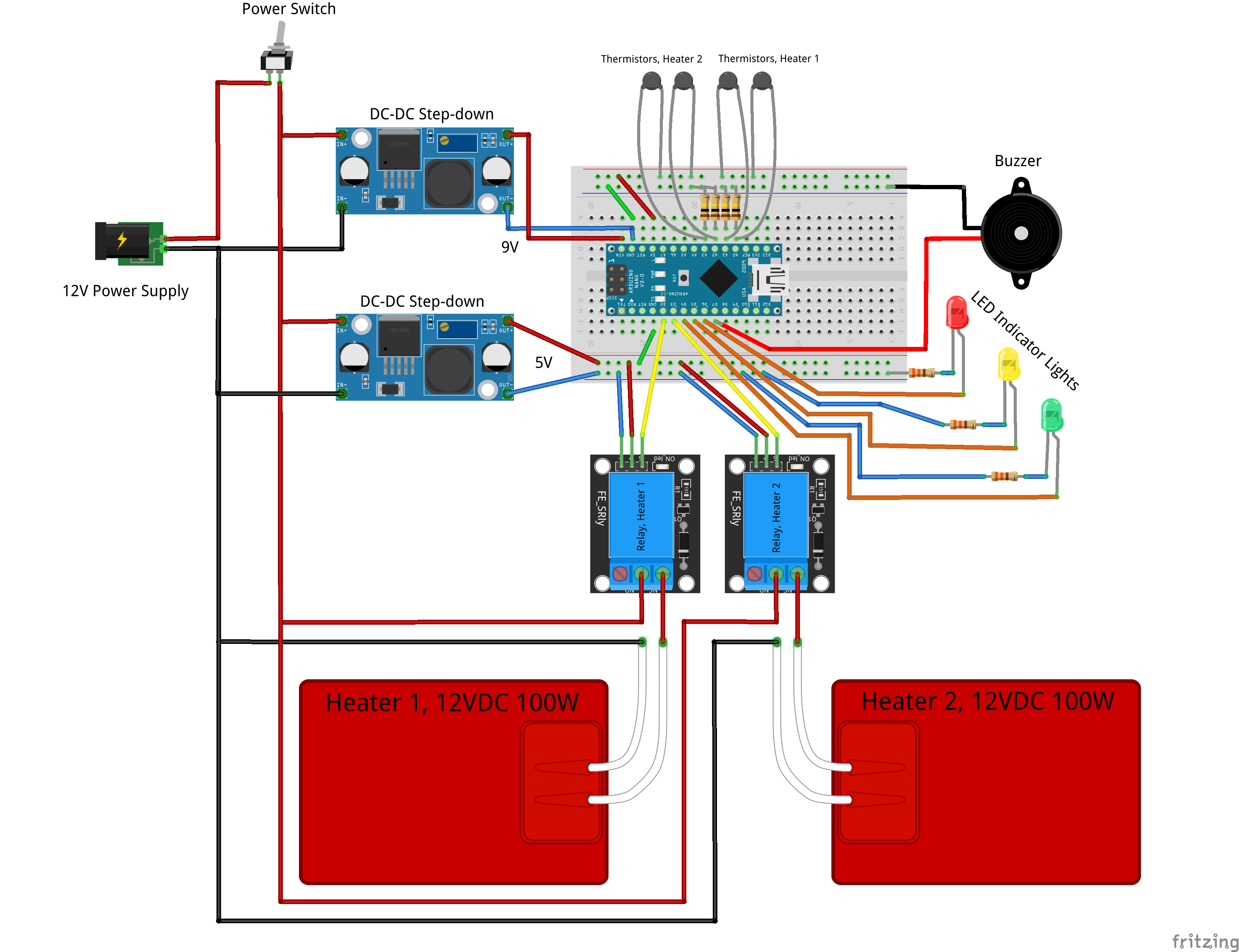
The OpenFluidWarmer prototype wiring diagram is depicted above. The "OpenFluidWarmer_BOM" spreadsheet in the files section of the OpenFluidWarmer Hackaday.io page details a complete bill of materials and where to source each component.
OpenFluidWarmer
a safe, low-cost IV fluid warmer solution; for when commercially available IV fluid warmers are too expensive or cannot be sourced
 John Opsahl