Close
0%
0%

Chip timing for every running club!

A chip timing device to measure your time on trails/hiking, interfacing with a cellphone through bluetooth

Similar projects worth following
Ever wanted to host a small running competition on your local running club, but was not easy to control timing of the runners? We have got a solution for you!.

Our proposal is a system that reads RFID tag's (carried by every runner) and registers them when passing by the sensor. The professional chip timing devices work exactly like that, but are too expensive for small running clubs around the country.

So every runner will carry either a key-chain sized tag, or a credit-card sized tag or even a flexible shoe-laced tag: when approaching the sensor (Arduino-sized box), it will recognized the runner and send timing information through bluetooth to any Android cellphone.

We are developing both the RFID tag reader (probably with an ARM Cortex-M4 Freescale controller) and the Android App (maybe an iOS App as well?). Our goal is to have a functional prototype by the end of August, when the school year starts. So that we can test it in our University running Club!.

Here is a flow-chart-like diagram of the proposed system:
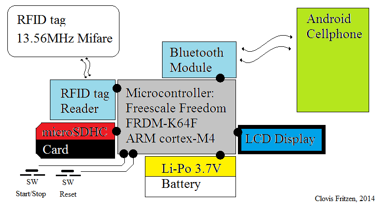
The complete system consists of a LAP/TIME controller (or logger) for runners or trail hikers, to monitor their performance in terms of time taken to perform certain task or run certain course.

Once the Tag holder (e.g. runner/hiker) approximates it to the RFID tag reader, this information is sent to the LCD display and microSD (to be stored), and a buzzer makes a BEEP; Optionally the event of a tag being read can be stored in the Android Cellphone memory, via our custom APP. The Start/Stop button shown in the picture stands to initiate or finish some preset time (the RACE TIME!).

So guys, just to make things clear and easy to understand, here it goes:

- The runner will only carry the Tag (or keychain), not the entire system. The little box with the ARM microcontroller, Bluetooth, RFID reader, LCD and keys will stay somewhere close to a cellphone, which will do all the heavy work of counting the number of laps, or time, etc.

- It will be possible to link the chip (RFID Tag) to the name of the runner (or his/her number), by typing it on the App screen before the race.

  • 1 × FRDM-K64F dev. board Freescale development board (ARM Cortex-M4), Arduino form-factor
  • 1 × RC 05 Bluetooth Module Breakout board, Bluetooth 2.0
  • 1 × RC522 RFID reader 13.56MHz RFID reader
  • 1 × Mifare RFID Tag ready for 13.56MHz reader
  • 1 × Battery Li-Po 3.7V to power the entire system

View all 6 components

  • On the way to go

    Clovis Fritzen08/06/2014 at 19:49 0 comments

    Hello Guys,

    I have been working on the C code for the project, and made some serious advances of it. I am being able to read the RFID tag and count a time, so it knows exactly when (in time) that exact card was read; It means that I am one step closer to the final system, that will control and log the runner's cards.

    I am also being able to display the card ID and the time on a 16x2 LCD display, which is helping me debug the system.

    Today is only August 6th, so we are really on schedule with the project. Expect some field tests for the next two weeks :)  . 

  • Bluetooth module - tested

    Clovis Fritzen07/25/2014 at 06:56 0 comments

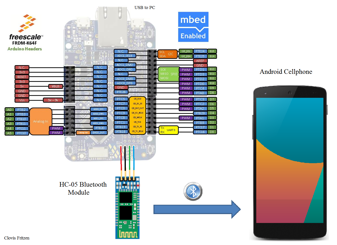
    Hello hackers, today I successfully tested my Bluetooth communication module (which I bought from a random eBay seller). The part number of this Bluetooth module is HC-05 and it connects directly to a 4-pin connector on my Freescale FRDM-K64F dev board, being supplied with 3.3V. 

    I am connecting my board to a PC via USB-serial (and using a terminal on PC) and the Bluetooth module to an Android cellphone, with an app called Blueterm. The code used for testing it is a simple "mirror": it gets info I type on the Android App and sends it to the PC terminal, and the other way around as well (text typed on PC is sent to the App on Android cellphone). The code I used is available on mBed platform and on my GitHub (links on the left side of this page).

    Schematic drawing of this connection can be seen below: 

    Next step will be testing the RFID tag reader and HC-05 Bluetooth together, reading cards and sending info to the cellphone and PC. 

  • RFID tag reader - tested

    Clovis Fritzen07/22/2014 at 18:19 0 comments

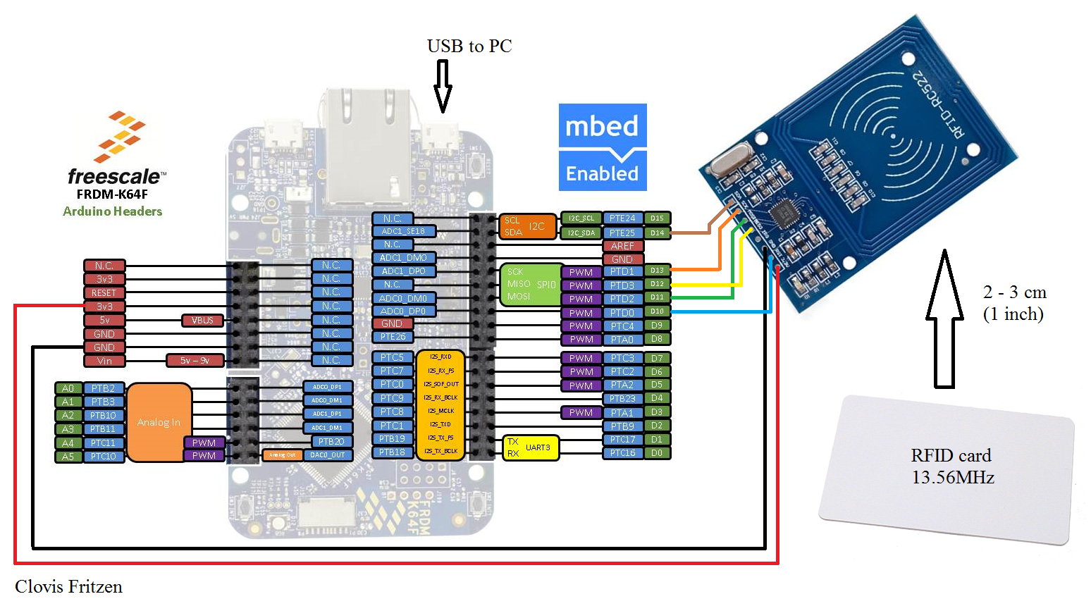
    I have tested the RFID tag reader board I bought on eBay (based on MFRC522 chip), hooked up to my Freescale FRDM-K64F board; it reads the ID and type of each tag and sends it via serial to my computer; The code is already available on GitHub (link in the left side of this page). Next step is to test my bluetooth module :) .

  • All the hardware in my hands

    Clovis Fritzen07/21/2014 at 22:18 0 comments

    Hello Voters, Hackers!

    Last week I got all the hardware I was in need to keep working on the project, shipped form China: One Bluetooth module and the RFID reader with some cards; This week I will be working on the code for both bluetooth and RFID. 

  • Started coding

    Clovis Fritzen07/07/2014 at 23:02 0 comments

    Just started coding for the project. We started coding the Freescale ARM processor in the mBed platform, using the already available Bluetooth and RFID libraries; I have already included the GitHub link to the repository. There has been an effort from the team to set up a initial version of the Android App as well.

    We haven't received any of the hardware ordered, so testing is out of question for the next week at least. Once we get our hands on it, there will even be a field test for you guys to watch on youtube. 

    We will keep you updated on the advances of the project. 

View all 5 project logs

  • 1
    Step 1

    First step is to make sure you get all the hardware in your hands (we bought everything from eBay):

    - One FRDM-K64F development kit from Freescale OR any other microcontroller platform capable of talking external devices (in that case you may need to port our original software for your custom application),

    - Bluetooth module (we are using the HC-05),

    - RFID reader and cards (we are using a MIFARE MF-522 module with 13.56MHz cards),

    - Battery for supplying the system (Lithium- Polymer 3.7V).

    - Small Buzzer (100 ohms resistor in series).

    - Optional On/Off/Reset

    - Optional 16x2 LCD display

  • 2
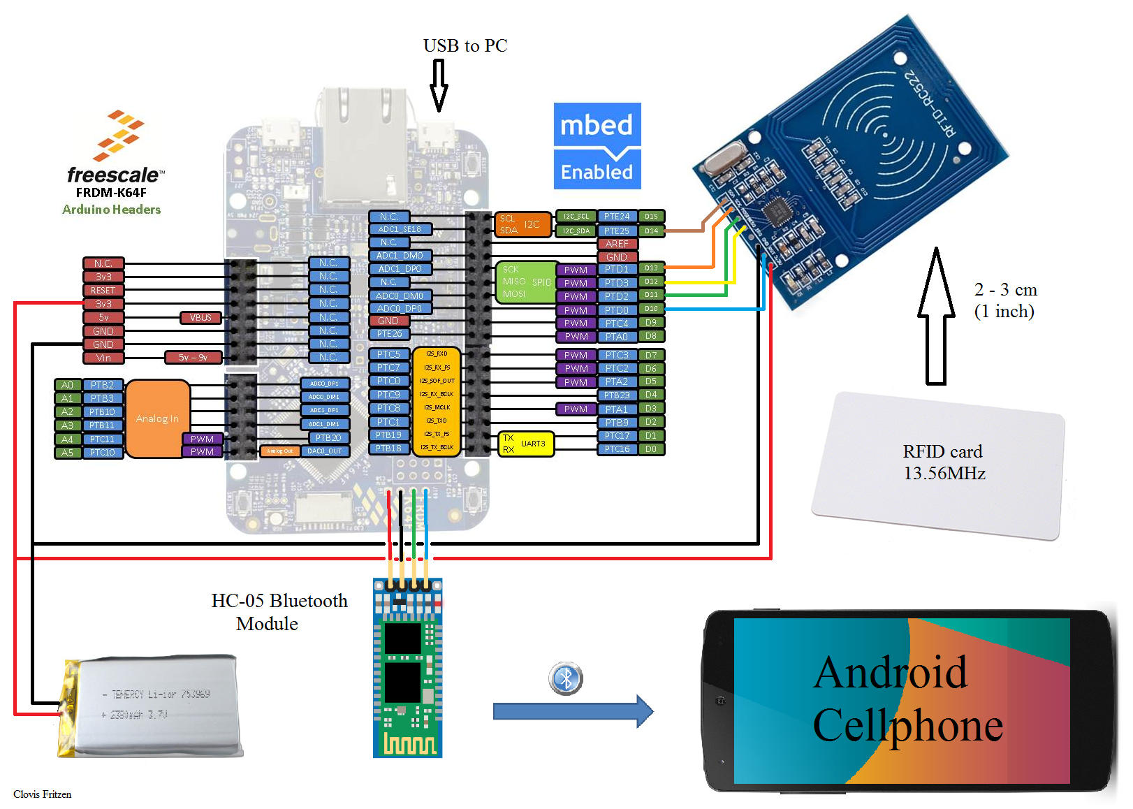
    Step 2

    Hook everything up together, as seen in the image below*:

    * more detailed instructions and schematics to come

  • 3
    Step 3

    the next step will demand a bit of coding, which we will be adding in the weeks to come...

View all 3 instructions

Enjoy this project?

Share

Discussions

sonyalisebastian wrote 12/01/2016 at 11:54 point

hey wer can i find the mbed code for this

  Are you sure? yes | no

quentin wrote 03/17/2015 at 09:41 point

Hi, 

is the project still on going? I'm currently looking for a similar project for a different type of race but would requiered at least 1 meter to track the time, please let me know contact me

  Are you sure? yes | no

Clovis Fritzen wrote 03/17/2015 at 12:02 point

Hello Mr Quentin; this project is currently not going :( , but you can totally get the mBed code in the links section of this page and adapt it for your needs. But as said by Mr Davedarko in the comments below, you won´t get to 1 meter using those 13.55MHz tags.. 

  Are you sure? yes | no

sonyalisebastian wrote 12/01/2016 at 11:54 point

hey im looking for mbed code wer can i find it

  Are you sure? yes | no

davedarko wrote 08/08/2014 at 22:11 point
Those RC522 modules have a reading distance of max. 4-5cms so it will be rather hard to achieve 1m reading distance. RFid is based on magnetic fields and as long as you don't use any active tags working with radio transmission, 1m is only achieved by massive coils, that need a lot of power.

  Are you sure? yes | no

Clovis Fritzen wrote 08/08/2014 at 22:19 point
That's true Mr. Davedarko; I am really considering using a active tag for the next version of the project.
I think it would be nice to even try with those 433MHz arduino radio links, or some sort of Bluetooth BLE.

  Are you sure? yes | no

Esker wrote 08/06/2014 at 21:03 point
Complex project to get reliable but I like the effort being made. Good luck. You mention 1m range.... Have you considered the RFID technology and the range capabilities? For low cost I presume you are using HF? Which is quite short range, that is shortened further by the presence of water/conductive bodies such as a person. I am wondering how you planned to mitigate these factors?

  Are you sure? yes | no

Clovis Fritzen wrote 08/06/2014 at 21:34 point
Hi Mr. Esker,

You are right, I am using standard off-the-shelf 13.56MHz RID tag. To increase the reading range I may try to use 125kHz Tag's, but not at this initial effort.

I may need to research deeper to figure out what technology is used on commercial chip timing circuits.

Thanks for the comment :) .

  Are you sure? yes | no

hof wrote 08/04/2014 at 21:42 point
Nice project!
You say the you are considering shoe lace tags which means the tags won't touch the reader itself. What kind of reading distance are you aiming for?

  Are you sure? yes | no

Clovis Fritzen wrote 08/05/2014 at 06:30 point
Thanks!

I am aiming for not more that 3ft (1 meter). The idea here is to make it a bit more flexible without compromising the cost of the system :)

  Are you sure? yes | no

Similar Projects

Does this project spark your interest?

Become a member to follow this project and never miss any updates