 Supplyframe DesignLab
-
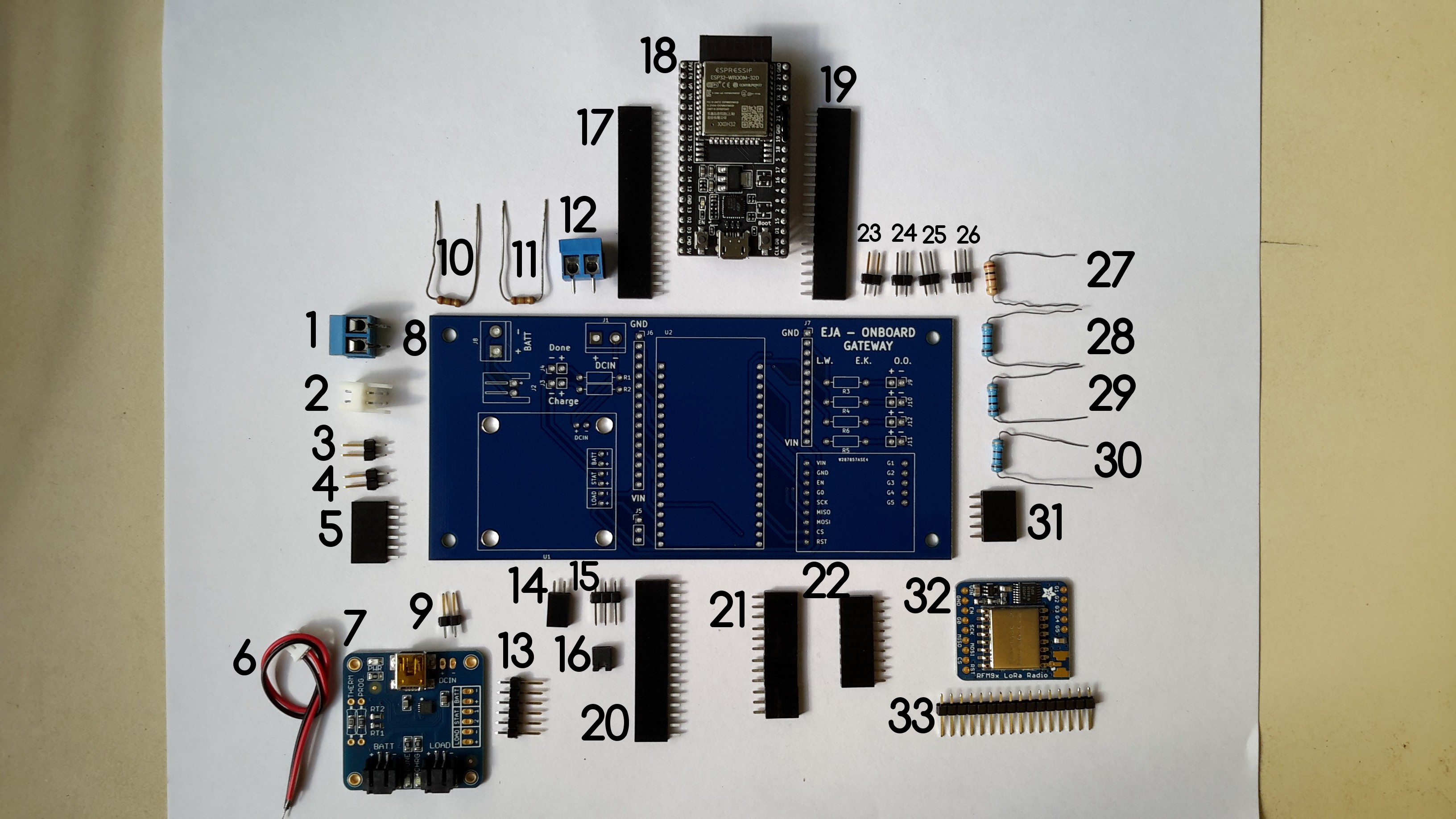
1Assembly of the Onboard Gateway V1.0 PCB
Solder the components of the Onboard Gateway V1.0 PCB. The following image shows all the required components, with an identification number.
![]()
Components list:
- TERM BLK 2P SIDE ENT 5.08MM PCB
- CONN HEADER R/A 2POS 2.5MM
- CONN HEADER VERT 2POS 2.54MM
- CONN HEADER VERT 2POS 2.54MM
- CONN HDR 6POS 0.1 TIN PCB
- 2POS JST cable (included in the USB LiIon/LiPoly charger)
- USB LiIon/LiPoly charger
- Onboard Gateway V1.0
- CONN HEADER VERT 2POS 2.54MM
- RES 249 OHM 1/4W 1% AXIAL
- RES 249 OHM 1/4W 1% AXIAL
- TERM BLK 2P SIDE ENT 5.08MM PCB
- CONN HEADER VERT 6POS 2.54MM
- CONN HDR 2POS 0.1 GOLD PCB
- CONN HEADER VERT 3POS 2.54MM
- CONN JUMPER SHORTING .100" GOLD
- CONN HDR 19POS 0.1 TIN PCB
- ESP32-DEVKITC-32D
- CONN HDR 19POS 0.1 TIN PCB
- CONN HDR 16POS 0.1 TIN PCB
- CONN HDR 12POS 0.1 TIN PCB (I used 2 CONN HDR 6POS 0.1 TIN PCB)
- CONN HDR 9POS 0.1 GOLD PCB
- CONN HEADER VERT 2POS 2.54MM
- CONN HEADER VERT 2POS 2.54MM
- CONN HEADER VERT 2POS 2.54MM
- CONN HEADER VERT 2POS 2.54MM
- RES 100 OHM 3W 5% AXIAL
- RES 100 OHM 3W 5% AXIAL
- RES 100 OHM 3W 5% AXIAL
- RES 100 OHM 3W 5% AXIAL
- CONN HDR 5POS 0.1 GOLD PCB
- RFM95W LoRa Radio
- CONN HEADER VERT 16POS 2.54MM (included in RFM95W LoRa Radio)
For a detailed explanation about the soldering and assembly procedure visit the following log.
-
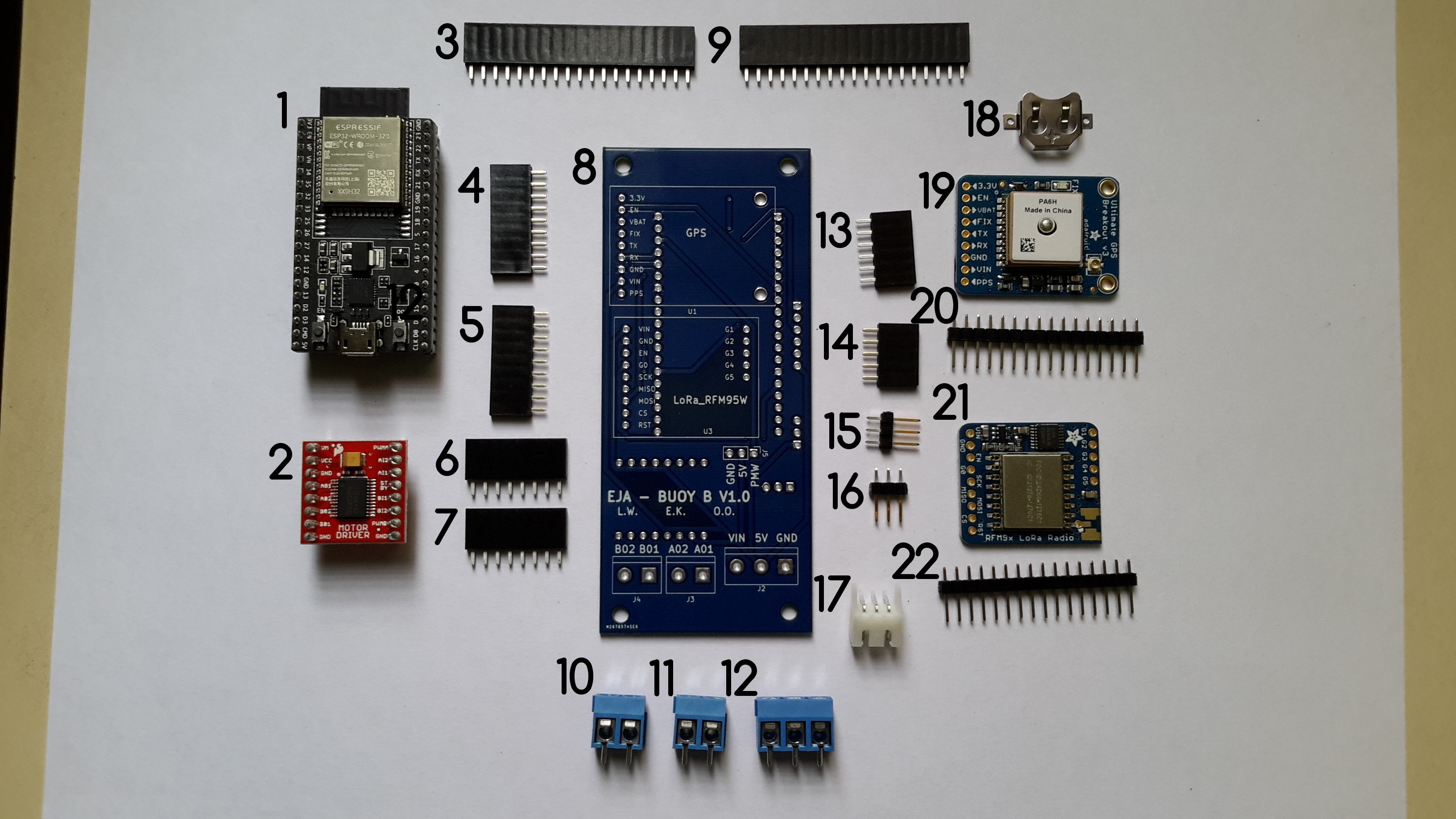
2Assembly of the Buoy B V1.0 PCB
Solder the components of the Buoy B V1.0 PCB. The following image shows all the required components, with an identification number.
![]()
Components List:
- ESP32-DEVKITC-32D
- TB6612FNG MOTOR DRIVER BOARD
- CONN HDR 19POS 0.1 TIN PCB
- CONN HDR 9POS 0.1 GOLD PCB
- CONN HDR 9POS 0.1 GOLD PCB
- CONN HDR 8POS 0.1 TIN PCB
- CONN HDR 8POS 0.1 TIN PCB
- Buoy B V1.0
- CONN HDR 19POS 0.1 TIN PCB
- TERM BLK 2P SIDE ENT 5.08MM PCB
- TERM BLK 2P SIDE ENT 5.08MM PCB
- TERM BLK 3P SIDE ENT 5.08MM PCB
- CONN HDR 6POS 0.1 TIN PCB
- CONN HDR 5POS 0.1 GOLD PCB
- CONN HEADER VERT 3POS 2.54MM
- CONN HEADER VERT 3POS 2.54MM
- CONN HEADER R/A 3POS 2.5MM
- Coin cell holder (included in Adafruit Ultimate GPS)
- Adafruit Ultimate GPS
- CONN HDR 16POS 0.1 TIN PCB (included in Adafruit Ultimate GPS)
- RFM95W LoRa Radio
- CONN HEADER VERT 16POS 2.54MM (included in RFM95W LoRa Radio)
For a detailed explanation about the soldering and assembly procedure visit the following log.
-
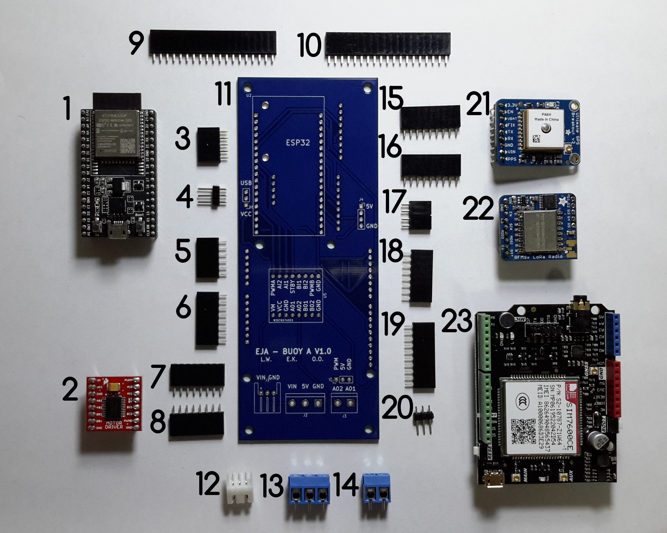
3Assembly of the Buoy A V1.0 PCB
This log describes the recommended assembly instructions for the Buoy A V1.0 PCB. The following image shows all the required components, with an identification number that will be used in the log.
![]()
Components List:
- ESP32-DEVKITC-32D
- TB6612FNG MOTOR DRIVER BOARD
- CONN HDR 5POS 0.1 GOLD PCB
- CONN HEADER VERT 3POS 2.54MM
- CONN HDR 6POS 0.1 TIN PCB
- CONN HDR 8POS 0.1 TIN PCB
- CONN HDR 8POS 0.1 TIN PCB
- CONN HDR 8POS 0.1 TIN PCB
- CONN HDR 19POS 0.1 TIN PCB
- CONN HDR 19POS 0.1 TIN PCB
- Buoy A V1.0
- CONN HEADER R/A 3POS 2.5MM
- TERM BLK 3P SIDE ENT 5.08MM PCB
- TERM BLK 2P SIDE ENT 5.08MM PCB
- CONN HDR 9POS 0.1 GOLD PCB
- CONN HDR 9POS 0.1 GOLD PCB
- CONN HDR 4POS 0.1 GOLD PCB or 2 CONN HDR 2POS 0.1 GOLD PCB
- CONN HDR 9POS 0.1 GOLD PCB
- CONN HDR 10POS 0.1 TIN PCB
- CONN HEADER VERT 3POS 2.54MM
- Adafruit Ultimate GPS
- RFM95W LoRa Radio
- SIM7600CE-T 4G(LTE) Arduino Shield
For a detailed explanation about the soldering and assembly procedure visit the following log.
2021 HDP Dream Team: EJA
Learn more about Team EJA's intelligent buoy, and how their solution will help the global fight against ghost gear.
Discussions
Become a Hackaday.io Member
Create an account to leave a comment. Already have an account? Log In.