Supplyframe DesignLab
-
Mech Update #17
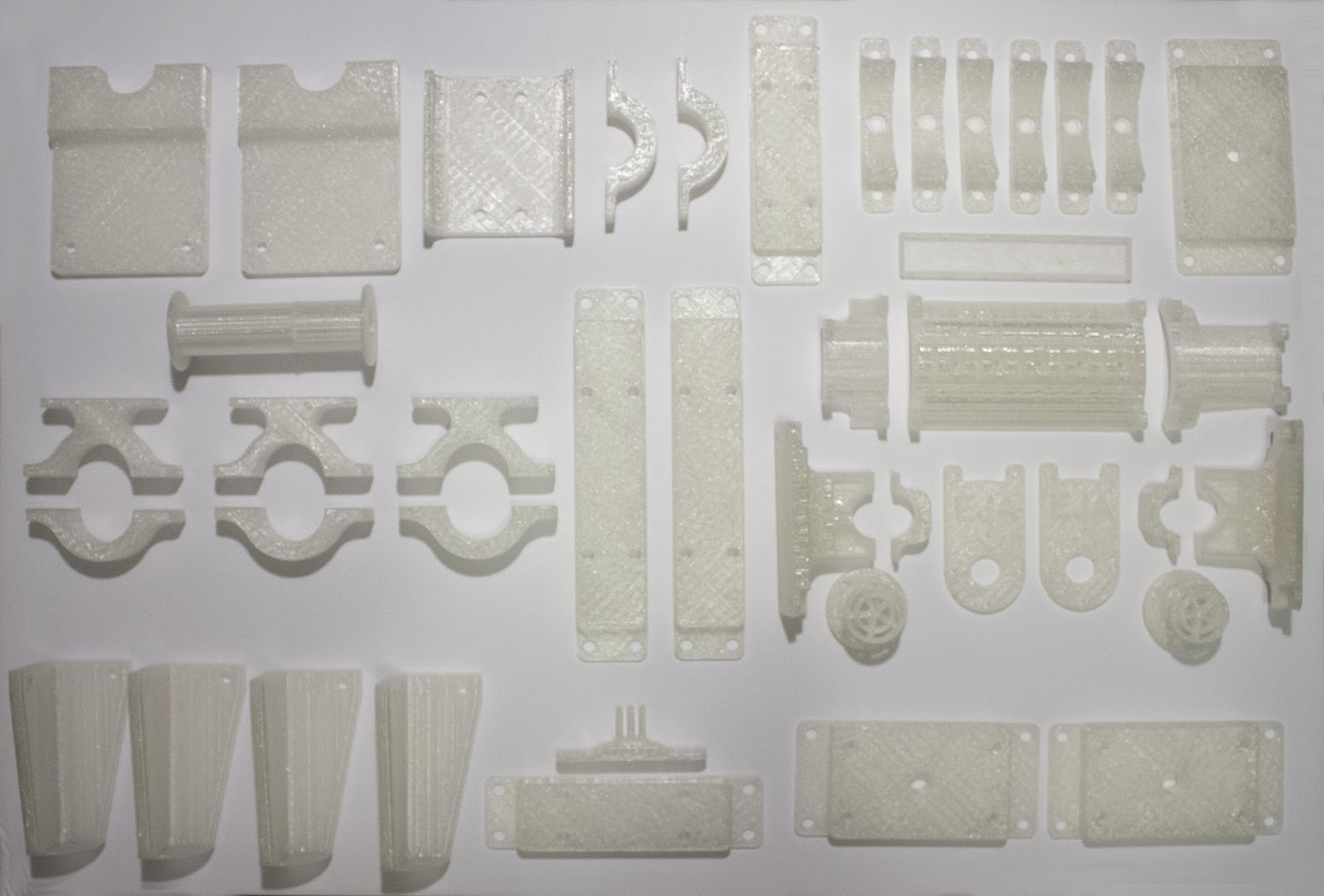
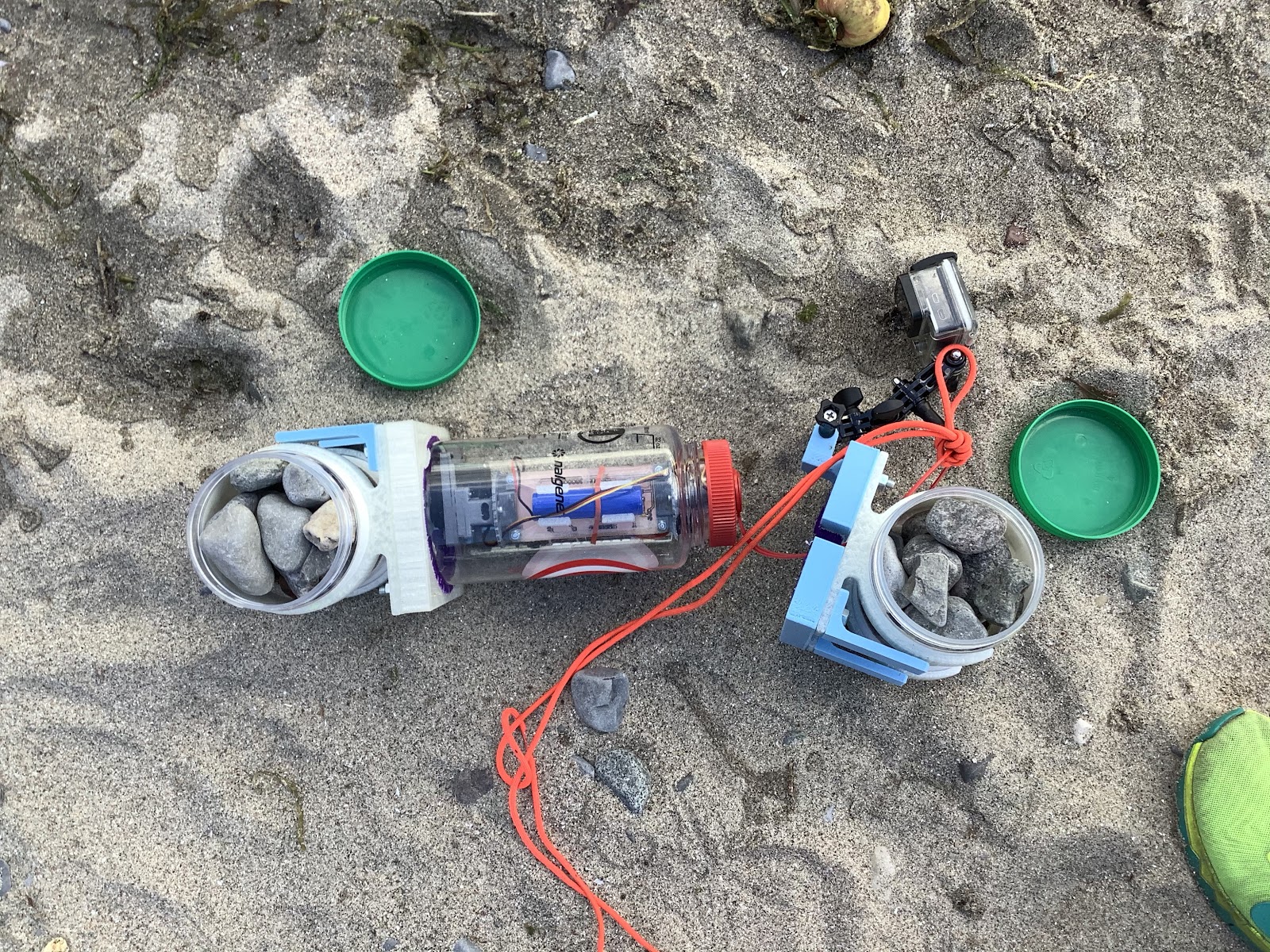
09/14/2020 at 17:55 • 0 commentsAll of the pieces have completed printing, and what’s next is to assemble it all! Here are all the pieces:
These pieces will attach to the HDPE top plate of the spool box. For now, we’re focusing on testing the release mechanism.
For weight, there is a 10lb dumbbell attached below the middle. Ideally, this load would have been spread out over two dumbbells, however - everywhere is sold out of weights because of the pandemic!
The external wiper takes on a bit of a wider form, serving as a way to hold down the buoy. It’s attached to a point on each end that use simple 3D printed sleeve bearings.
The rope that attaches to the buoy can be attached to the spool. This isn’t the final design of what the solution would be, but it will allow us to test properly.
There will be a rope attached to the handles for placing the whole assembly in the water and bringing it up. There’s a GoPro mount near the front that will be able to see how everything works underwater.
The process of design for this was to design a piece, print it, then before that was done, design the next piece and print it, etc. Idea here being that it’s more suitable to multi-tasking. One of the caveats to this approach is that ideally, a dedicated amount of time could have been spent on the spool box, and that could have been cut out of HDPE at DesignLab. One of the benefits of going this slower 3D printed approach, is that all of these brackets and attachments can be easily iterated on. Ran into a bit of an issue with my 3D printer with X-axis layer shifts (but only at a certain Y position), and figured out a workaround for now.
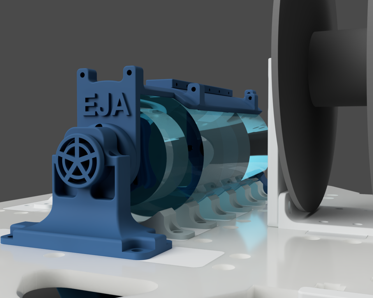
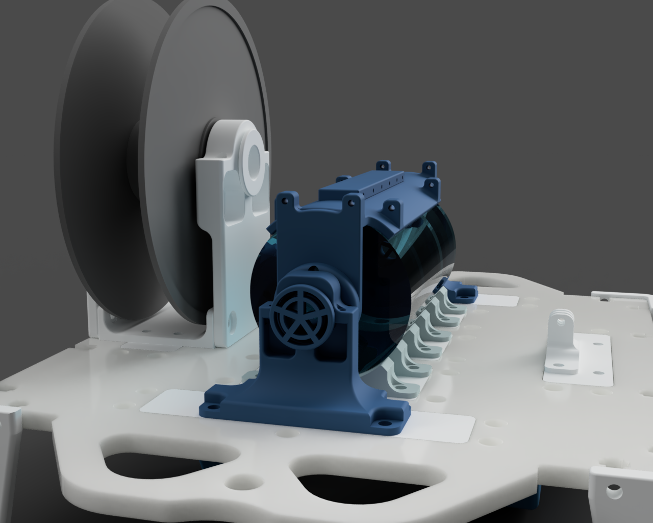
Next step is to assemble it all! All of the pieces should attach together as simply as this, but in reverse:
This morning it was really energizing to see Leo’s and Tobi’s progress on the boards and coding. We even got to see a sneak peek of the finished circuit boards from Tobi live at the company’s HQ. Leo explained about some of the code he had the chance to write, and even implemented OTA updates. Hopefully they will post project logs about this soon!
Thanks again to the DesignLab for milling the top plate piece out of HDPE. Time to go and assemble the pieces!
-
Mech Update #16 - Test #03
09/12/2020 at 06:01 • 0 commentsNote: The content from this log was on Sept. 4
With the results from Test #02 along with Leo’s buoyancy calculations, it was time to try another test.
Objectives of the test
- Verify the external wiper moves along with the internal wiper while in water
- Verify the ballast works
- Compare the results with the conditions from Test #01 (wave height ~2 cm) to Test #02 (wave height ~15 cm) to Test #03 (wave height ~20 - 30cm)
This is what the new setup looks like:
Here it is, the external wiper working, underwater and even with the waves!
Read on for the results and more info
---------- more ----------The waves were particularly high for this test. Good conditions to stress test it a tiny bit more:
Here’s the buoy being pushed around underwater with the current, and the wiper is attached and working!
It’s exciting to see that result. Might seem small, but it allows moving on to the next step of the larger release mechanism.
Here was one of the fails. The block that attaches to the lid fell off due to being heavier with the ballast now.
Worth a try, but nope, a rock did not help:
This was an interesting moment in the test when the ballast detached:
That scenario gives a preview of what the release mechanism result would look like - a buoy floating on the surface:
Let’s see if this similar result can be achieved with the next design.
Here are the learning lessons from this test:
What changed
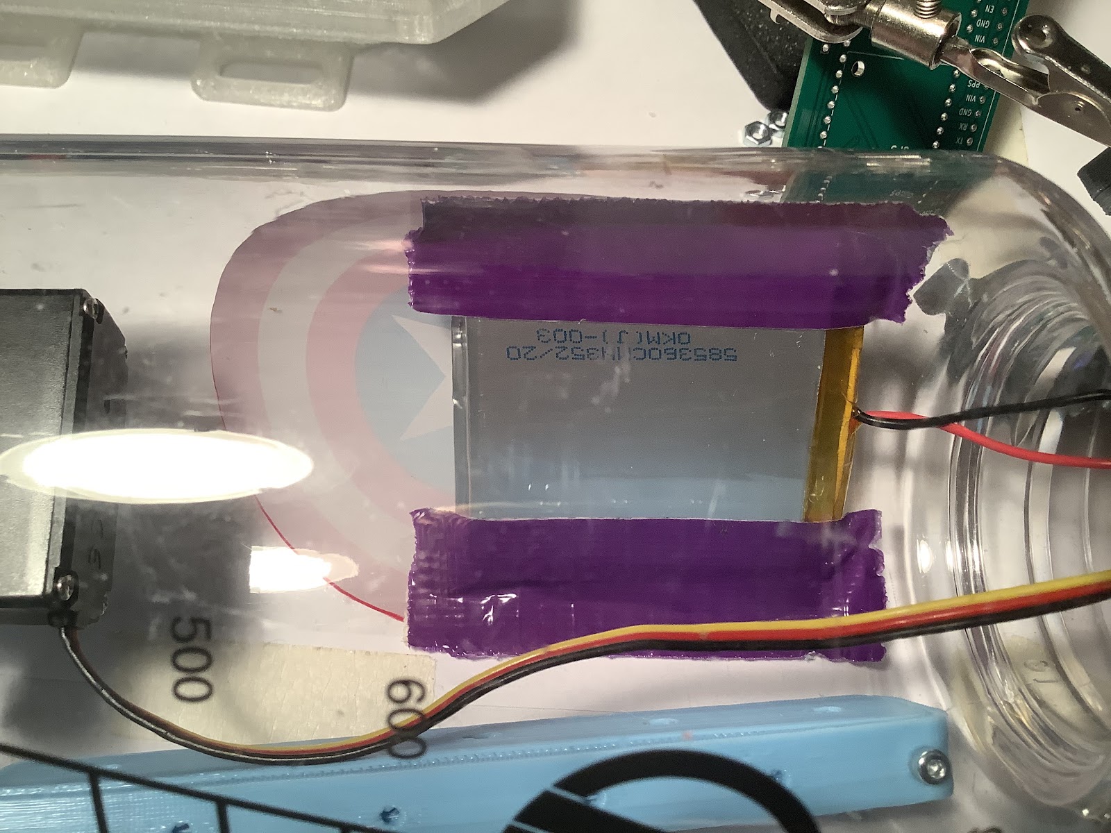
There were a few changes to the setup. Most notably, there’s clamps on the ends of the buoy that attach in 2x 1kg peanut butter jars. The new batteries arrived, so there’s an 18650 cell attached to a 3d printed bracket behind the circuit board. This eliminates the LiPo that was attached to the inside wall preventing the servo with internal wiper from moving properly. The neopixels were not lighting up after test #02, and this remained unchanged due to scheduling.
The lipo batt was curved slightly after removing from the nalgene:
Here’s the 18650 on the batt clip:
What worked
- External wiper confirmed to work in the water!
- Achieved less buoyancy with the two containers filled with sand and water
What didn’t work
- Containers filled with rocks (contained air pockets)
- Containers filled with dry sand (contained air pockets)
- Trying to attach rope to a rock and use that as ballast
- Forgot to print a proper attachment point for the rope, so it was attached to the ring on the nalgene lid
Here’s the rocks and air in the container - this didn’t work, so it was changed to sand, then changed to wet sand - which did work:
What needs to change for future version
Actually, that’s it for iterating on this! The hypothesis about the wipers has been validated now, and the next step is to work on the release mechanism assembly design. That’s what the large hdpe piece will be used for.
Guiding the preparation for the next test is the release mechanism.
By the way, here’s what the peanut butter jars look like in case anyone was wondering :)
(And yes, it is very unhealthy *and* delicious)
-
Debugging Basic Functionality
09/11/2020 at 05:42 • 0 commentsNote: The content from this project log was from Sept. 5th.
We were still waiting for the boxes to arrive to Leo and Tobi (luckily, now, as of writing this, Leo’s box has arrived and Tobi should be receiving it today). Remote debugging testing code proved to be unproductive for numerous reasons. The next step was for me to dive into programming the basic functionality and debugging since I had all the pieces here.
Power Jumper
First change was making the Vcc - Usb power jumper tied on Buoy A and B. This means that everything would be powered on from the usb port. The switching of the jumper was time consuming during the debugging process.
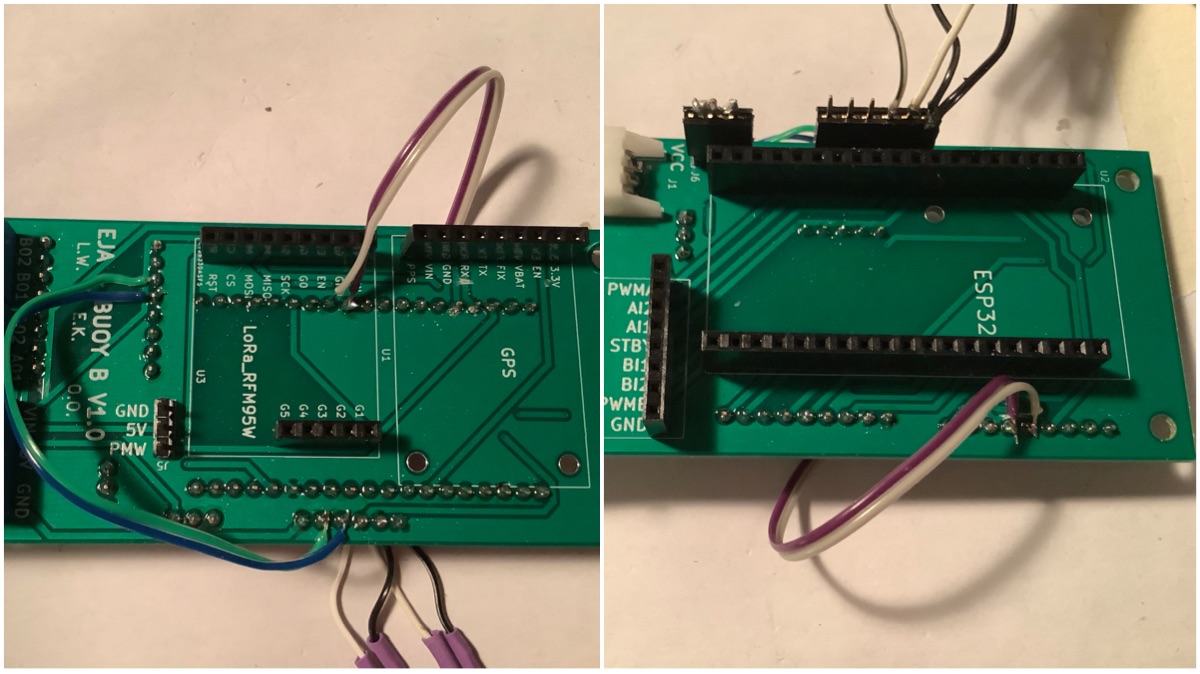
GPS - Buoy B
Next change was moving the GPS from Serial0 to Serial2. The reason for moving is because Serial0 is used as a programming and debug port. This meant that programming did not work when the GPS was powered on. Serial2 is on GPIO 17 (TX) and GPIO 16 (RX). The Ultimate GPS logic level is 3.3V, same as the ESP32. In order to move to those pins, the motor controller channel B pins had to be moved.
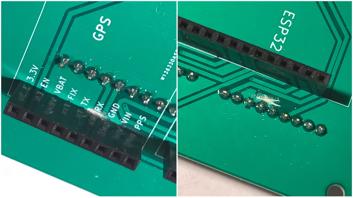
Cutting motor controller traces:
Cutting GPS TX & RX traces:
Conductivity test to make sure the traces were cut:
New wires added:
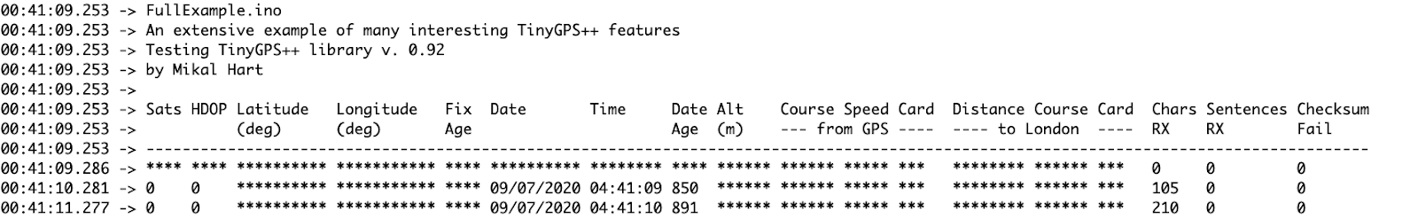
The next step was to use the TinyGPS++ library. This is what we used for Bowie the robot, and it has proven to be extremely useful at parsing the NMEA data. After holding the Buoy B at the window, it resulted in a fix and data:
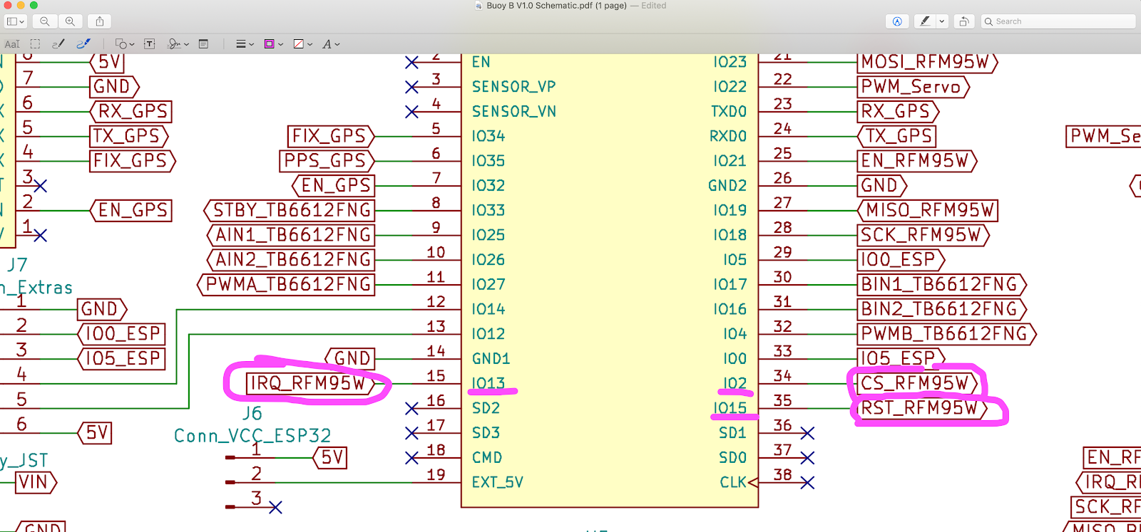
One thing about the changes - the motor change moves the wires to the pins that Leo proposed the RTC to be added to. An option is to remove motor channel B all together. It’s likely that only one channel would be needed for the foreseeable applications for now.
GPS - Buoy A
Next up is a similar change with Buoy A. Buoy A is different, as it has the SIM7600 on Serial2. At this point I figured using Serial1 for GPS would be fine, however that proved to be false. The reason why is because the pins Serial1 is on (9 & 10, aka SD3 & SD2) are used by flash when QIO is enabled. Next, I tried uploading in DIO, QOUT, and DOUT. DOUT was the only one that worked without Guru errors. However, no data was received. A quick swap of RX and TX was done just in case, however it was the same result.
Time to try a software serial option. Moved the GPS to software serial on pins IO12 and IO0. It works, however cannot upload when those pins are in use, and so have to disconnect the power jumper. To be clear regarding the pins: GPS RX -> IO12, and GPS TX -> IO0. These can be swapped by the SoftwareSerial object anyway.
Cutting the GPS traces:
Adding the GPS wire:
Seeing it work (yay!):
LoRa
The LoRa connection is working. The reason why it was not working through remote debugging was because the pins were defined incorrectly through multiple tests. Additionally, the test code was trying to test too many subsystems at once. The solution was to 1) read the datasheet, 2) write the proper numbers in the LoRa library example code. After going back to the basics, the LoRa code worked fine between Buoy A & B to the Onboard Gateway.
Reading the datasheet:
Additionally in the code, added a few lines to make the LEDs blink when sending and receiving. Makes it easy to visually check it’s working.
Code
Here is the code to test the basic functionality:
*Note: The code is in a private repository for internal testing for now
Now that Leo has the box, and hopefully soon Tobi, programming and debugging will likely ACCELERATE! :)
Notes
Here are my notes from the debugging journey
-
Debugging SIM7600
09/07/2020 at 19:39 • 0 commentsIt’s time to debug the SIM7600 module and see if that can work. Here’s the board we’re using.
Here are the important things to know for setup that took me a while to figure out:
- This shield needs to be plugged in to an external power source to work
- Cellular antenna attaches to Main
- Leave the jumpers as is
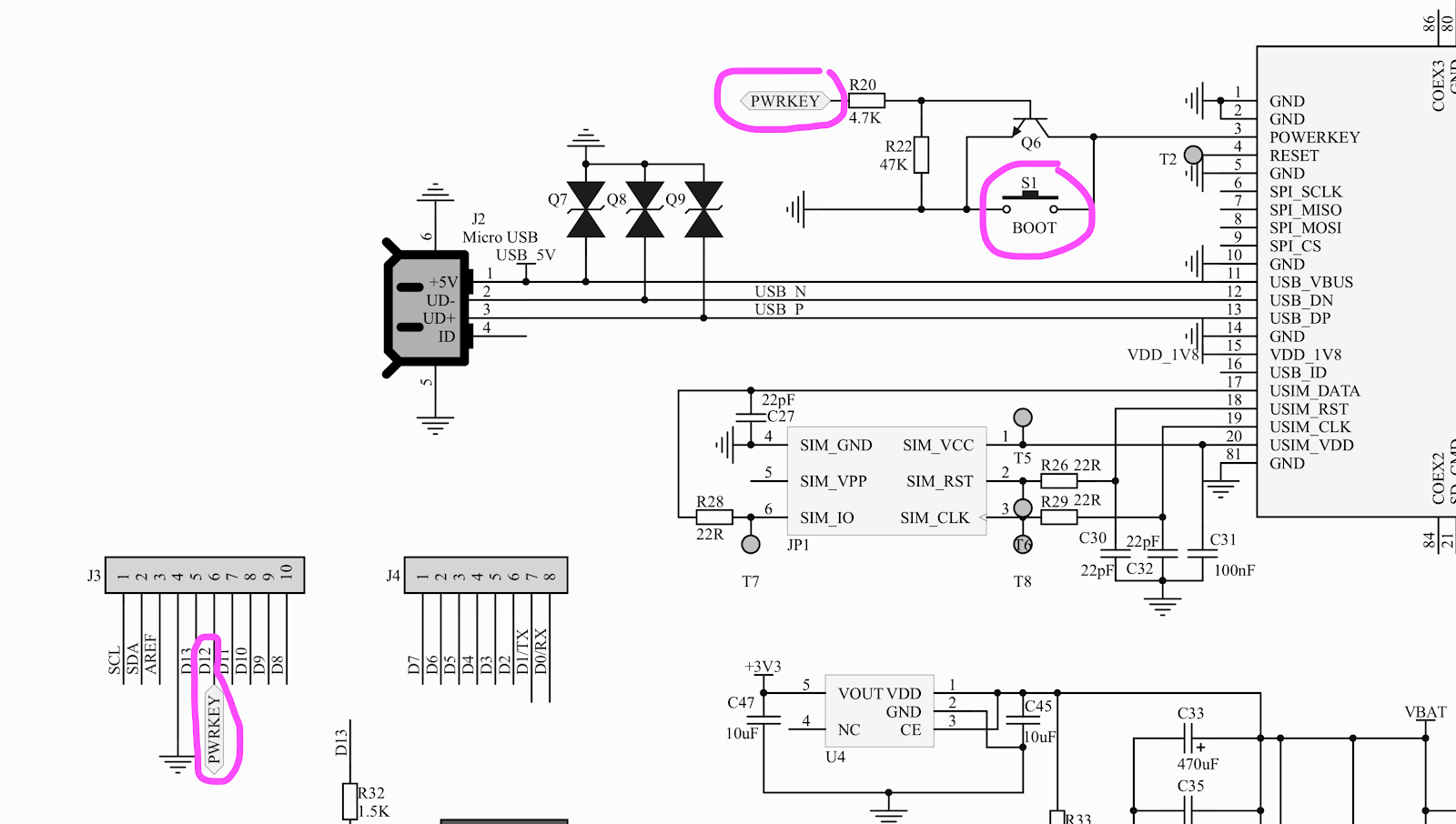
- Press Boot for 1 second to start the modem
- The blue ‘Net’ LED should be blinking once every second once it’s connected
- Even though SIM7600 is said to have auto-baud, it actually is not. The baud is 115200.
Boot is connected to Arduino pin 12:
After figuring out all the above info, and hard coding the messages in as a String to be sent (instead of individual chars from reading the Serial Monitor), was finally receiving data from the module on the Arduino:
However this good news did not last for long as the Arduino is using SoftwareSerial, which isn’t very reliable after speeds of 19200 baud. Below you can see the garbled messages happening.
Time to switch back to the ESP32 to see if their Hardware Serial improves things. It does! And here you can see we are on Hologram:
The Hologram SIMCOMM library has a sequence of AT commands to send to the modem module. Their library is for SIM800 or SIM900 series, but there’s no reason that we can’t find a way to make it work with SIM7600. Following the Hologram init sequence in this function:
bool HologramSIMCOM::_connectNetwork()Here are the commands being sent:
- AT+CGATT? = check gprs status
- AT+CIPMUX=1; = set connection mode to multi
- AT+CSTT=\"hologram\"; = set apn
- AT+CIICR; = bring up wireless connection
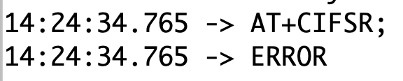
- AT+CIFSR; = get local ip address
The sequence fails at:
- AT+CIPMUX=1;
Which is to set the connection mode to multi. The subsequent AT commands after that also fail.
What could cause this? Do we already need to send the device key that Hologram provides for each sim? Not quite. This is only needed when sending messages. Here you can see where the device key is added in to the message in this function:
bool HologramSIMCOM::send(String data, const String topics)What is the actual AT command for sending the message? First, a TCP connection needs to start, then we send how long the message is, then we send the data:
The process is pretty close, but why it is failing at AT+CIPMUX=1; remains unknown for now. This is where it is stuck on my end.
It would be worthwhile to test with a “regular” SIM to see if this module is functioning properly. For me, even the ATD command is not working (to place a simple voice call), it says NO CARRIER. I don’t have a regular sim that I’m willing to sacrifice and test, but maybe Tobi and Leo do.
Testing the sms command, it worked!
AT+CMGS=\"phone number here\";

Testing 123456 Eja 1234

0x1A
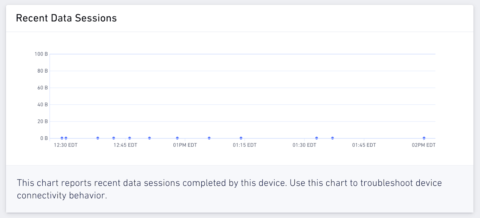
First sms message received from Buoy A! It’s not completely reliable just yet, as with some experimentation the module has been getting stuck. Well, there’s a reason why it has been getting stuck:
Sorry about that Hologram! The debugging chart in Hologram’s dashboard has been interesting. It shows some start / end timestamps of 0 byte data transmissions to the network.
Well, now after the whole day spent on this now, the pressure is back on to get back to mechanical design, fabrication, and assembly.
At least we know now, the SIM7600 is functional, and it might be interesting to look into getting a sim card for any local demos.
-
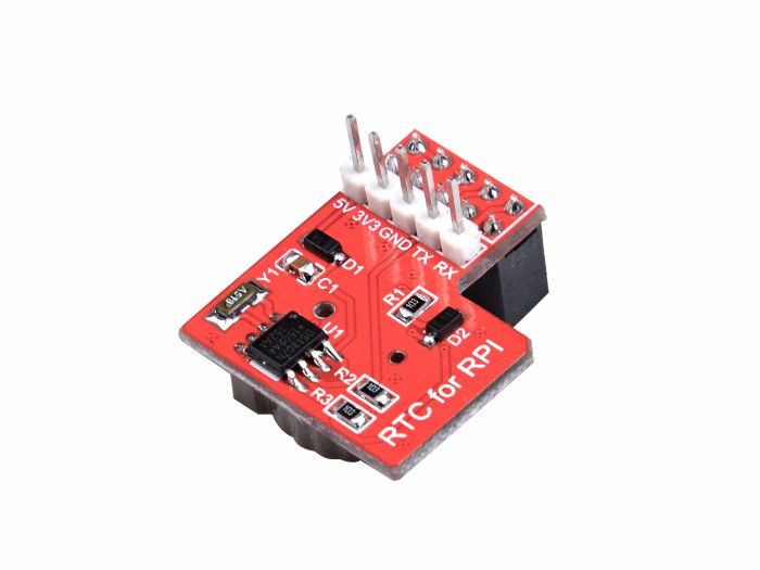
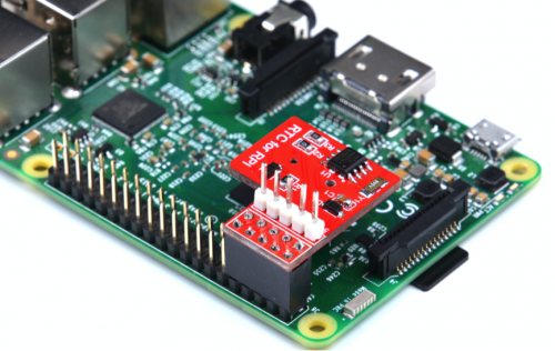
Additional Modules - Raspberry Pi RTC Expansion Module v1.1
09/06/2020 at 16:24 • 0 commentsOne of the modules that can greatly improve the original design of the Buoy (A and B) is an RTC. In this log I'll analyze the Raspberry Pi RTC Expansion Module v1.1 (Datasheet, Wiki) and explain how to adapt it to the PCB design Buoy B V1.0.
![]()
This module uses a Maxim DS1307 chip and contains a cell backup, it has been designed specifically for the Raspberry Pi.
![]()
Since we want to use the Module with the ESP32 we need to understand the main connector in the module. At this moment the wiki does not contain a diagram that explains the connector, but is easy to figure out the pinout using the Raspberry PI 2 as a reference.
![]()
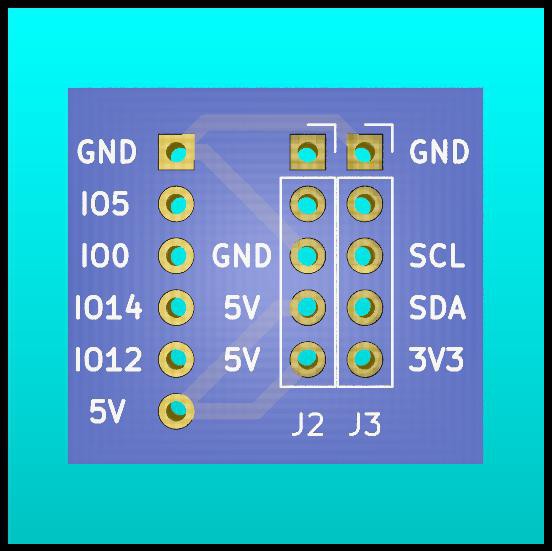
The RTC Module connects to the pins 1, 2, 3, 4, 5, 6, 7, 8, 9 and 10. With that information it is possible to identify the pinout of the board:
![]()
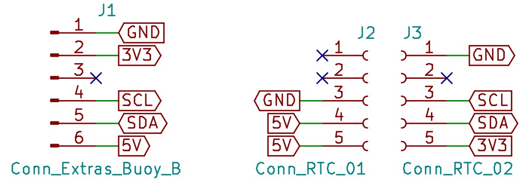
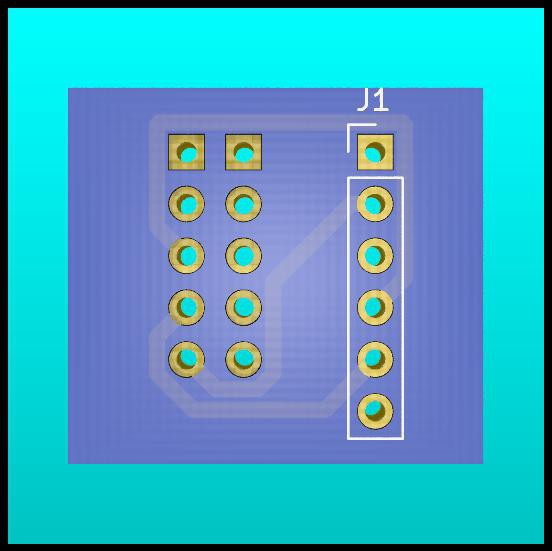
Based on the pinout, I designed a small PCB (using KiCad) used to adapt the RTC Module to the PCB Buoy B V1.0 (J7 Conn_Extras). This design can be used as an example, and can be easily replicated in a PCB breadboard.
Schematic:
![]()
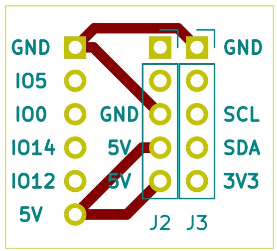
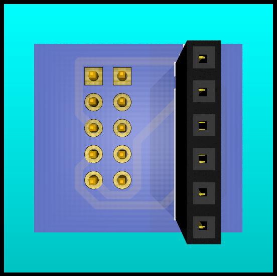
PCB Front Layer:
![]()
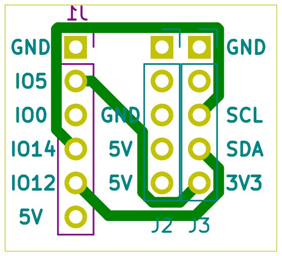
PCB Back Layer:
![]()
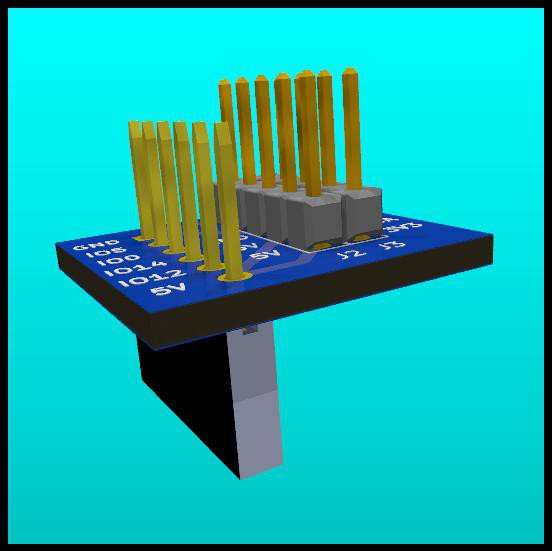
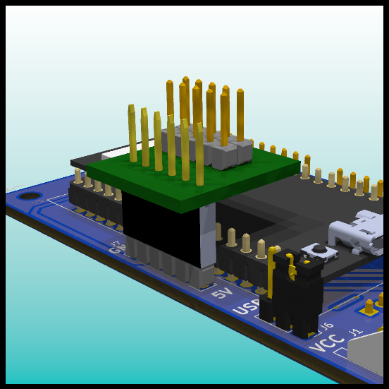
3D Model
![]()
![]()
![]()
![]()
![]()
![]()
![]()
Note: The labels in the connector in Buoy B V1.0 (J7 Conn_Extras) are slightly different than the one presented in the original schematic. That schematic has a mistake in the label names for this connector. This information will be explained in future logs.
-
Buoyancy Calculations
08/30/2020 at 03:43 • 0 commentsIn this log I'll present 2 design examples, in each case I'll evaluate simple equations in the field of Fluid Statics to answer common questions and verify how each design performs under specific circumstances.
Theory
To start the analysis I'll briefly present a brief explanation of the equations and concepts that will be used in the following design examples.
Archimedes' Principle: any body completely or partially submerged in a fluid (gas or liquid) at rest is acted upon by an upward, or buoyant, force, the magnitude of which is equal to the weight of the fluid displaced by the body.
Where
Since we are designing devices that will work on seawater at different depths, I'll be using following table with density changes depending on depth (seawater 35 parts per thousand and 0 °C):
Depth (m) Pressure (decibars) Density (kg/m^3) 0 0 1028.13 1000 1000 1032.85 2000 2000 1037.47 4000 4000 1046.40 6000 6000 1054.95 8000 8000 1063.15 10000 10000 1071.04 For our design we need to consider 2 specific situations:
- The object is floating at the surface
The sum of all forces that act upon the object must be higher than zero to assure that it floats to the surface, in that situation there is a force in the positive vertical axis that affects the object. When the object arrives to the surface the acceleration descends to zero. To assure that the object floats at surface level:
It is common to add a safety factor to the mass in the equation [1], a small fraction of the mass is added to consider small differences between the design and the real platform or measurement errors. This factor is usually picked between 1% and 5%.
In this equation m represents the total mass of the object, that is the sum of the submerged platform or structure and the buoyancy material.
- The object dives until it reaches the desired depth
Opposed to the last example, the sum of forces that act upon the object must be lower than zero to assure that it sinks, in that situation there is a force in the negative vertical axis that affects the object. When it reaches the bottom of the ocean it stops moving in the vertical axis, to assure that the object stays at the desired depth:
In this equation m represents the total mass of the object, that is the sum of the submerged platform or structure and the buoyancy material.
Similar to the last example, it is recommended to add a safety factor to the mass of the object (can be between 1% and 5%) [1] :
If the design requires additional ballast, it is possible to add it to the equation:
Design Example 1
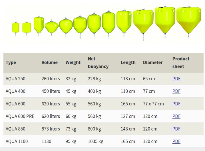
For this example I used catalogs to find real buoys and ropes. First I found a buoy catalog:
![]()
Net Buoyancy
With the available data is very easy to verify the calculations used to determine the Net buoyancy in this catalog. For example for the model AQUA 250:
The fluid considered in the catalog is water. In further calculations I'll use the density of seawater, and I'll adjust depending on the depth.
Ballast
How much weight should a ballast have to sink the buoy to a 500 m depth?
With a seawater density of 1032.85 kg/m^3 and a safety factor of 5% we can calculate the mass of the ballast:
How can we interpret this result? Can we just find something with a 234.941 kg weight and use it as a ballast?
Is not as easy as that, it is important to remember that any object used as a ballast will occupy a volume under water. The ballast will also be subject to a buoyancy force.
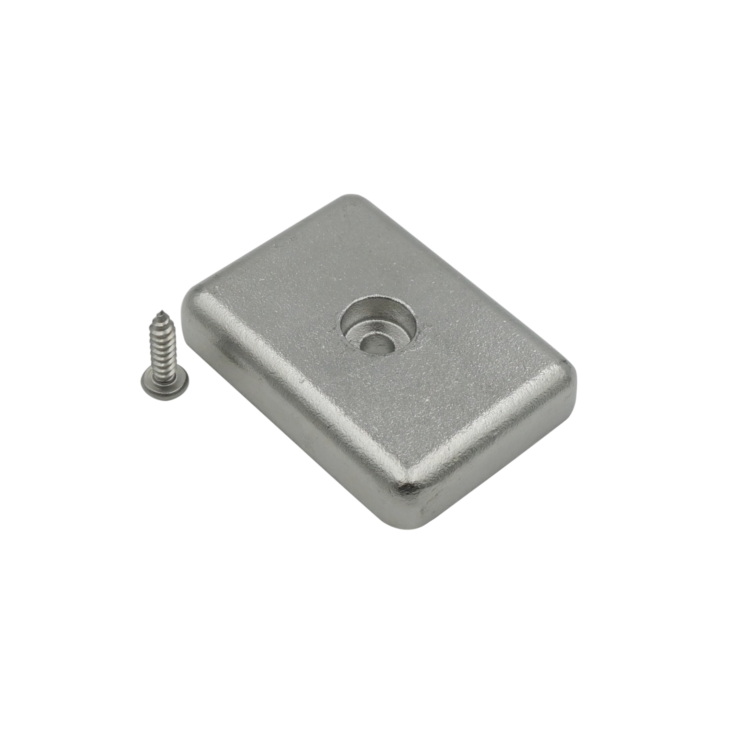
For example, we can use a commercial solution for the ballast: a stainless steel ballast weight.
![]()
The manufacturer of the ballast provides the weight in air (191 g) and a weight in water (165 g). Having the weight in water facilitates the calculations, to sink the buoy in our design we would require 1424 ballasts.
It is recommended to verify how the manufacturer calculates the "weight in water", to be sure of the characteristics of the fluid. Using the volume and the weight of the alternative used is enough to calculate the net buoyancy of the ballast and then calculate the "weight in water".
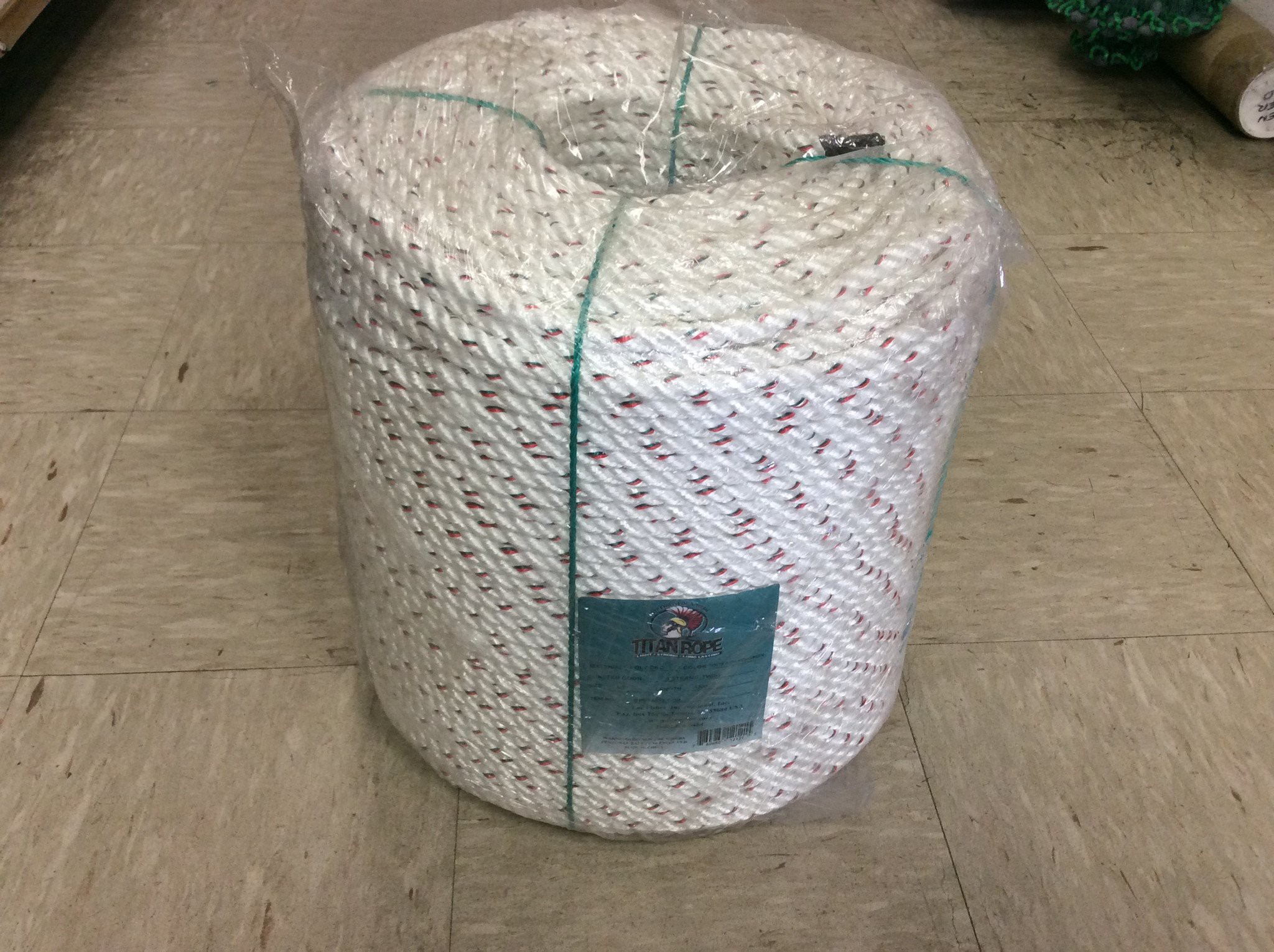
Rope and Ballast
Our design requires a rope that connects the buoy and the fishing trap. To add that element to the design I selected a commercial rope (as example) that is used to pull crabs and lobsters traps.
![]()
The characteristics of this pack are:
Length = 1200 ft = 365.76 m
Total Weight = 50 lbs = 22.67 kg
For this example I will analyse 500 meters of rope, the total weight for that length is 30.99 Kg. For a ropeless gear situation we can analyse 2 situations:
- The buoy is at the bottom of the ocean, attached to the rope and the trap. Considering our buoy and our rope, the require ballast mass is:
- The buoy is at the surface, attached to the rope. In this case it is possible to calculate the fraction of buoy's volume that stays submerged.
Design Example 2
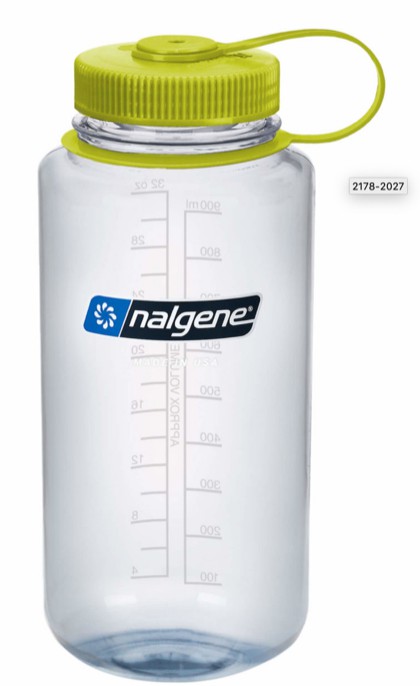
For this example I used a 32 oz Nalgene Bottle as the buoy. The bottle has a volume of 0.94635 litres and a weight of 0.1772 kg.
![]()
Net Buoyancy
The net buoyancy of the bottle (close to the surface) is:
Ballast
How much weight should a ballast have to sink the buoy to a 500 m depth?
With a seawater density of 1032.85 kg/m^3 and a safety factor of 5% we can calculate the mass of the ballast:
Using the the stainless steel ballast weight from the last design example, it is possible to calculate how many of them are required to sink the buoy in this design.
If we decide to use that commercial model, we would require 5 of them to sink the buoy.
Rope and Ballast
Using the same rope from the last design example I can calculate the maximum length of rope that can be attached to the buoy without sinking it.
Considering the characteristics of the rope used in the last example: Length = 365.76 m and Total Weight = 22.67 kg.
References
[1] J. Cappelletto, M. Massot-Campos, A. Bodenmann, S. K. Das and B. Thornton, "Micro-Ballast Dispenser for Long Endurance Underwater Mapping Platforms," 2019 IEEE Underwater Technology (UT), Kaohsiung, Taiwan, 2019, pp. 1-8, doi: 10.1109/UT.2019.8734317.
-
Buoy A V1.0 - Wiring Diagrams
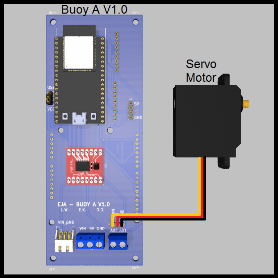
08/28/2020 at 13:09 • 0 commentsThe following diagrams present the physical connections of the different boards and components of the Buoy A V1.0.
Motors
The board was designed to handle 2 different types of motors, those are:
- Servo Motor
![]()
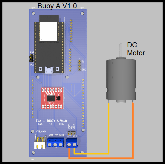
- DC Motor (using the driver TB6612FNG)
![]()
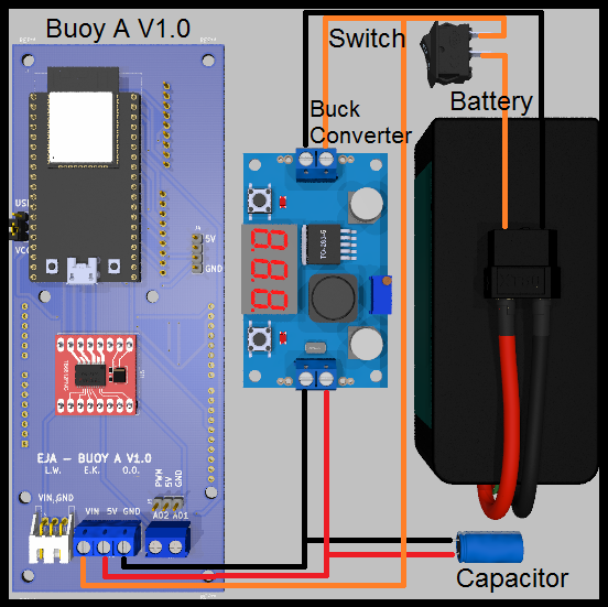
Battery Management
The original design of the board considered the following components:
- Battery (5V < Voltage < 15V)
- PCB Board Buoy A V1.0
- Buck Converter
- Switch
- Extra capacitor
![]()
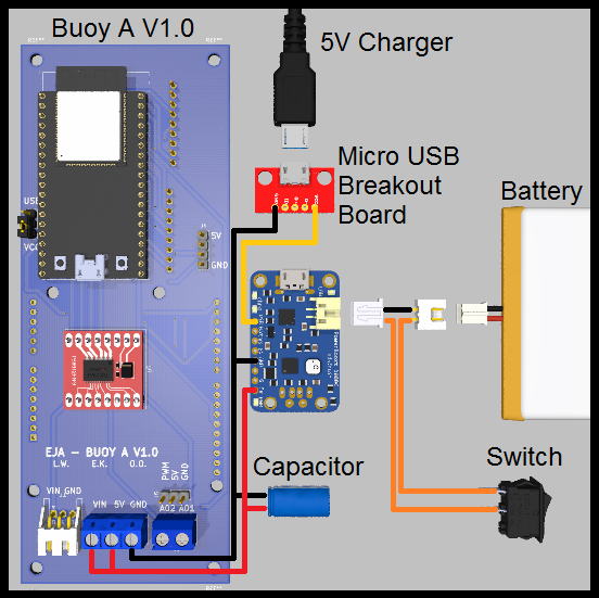
Similar to Buoy B, there is an alternative for the battery management, is possible to provide the required voltages with a boost converter and a 3.7V Battery, like the following example:
- 3.7V 1 Cell Battery
- PCB Board Buoy A V1.0
- Boost Converter
- Micro USB Breakout Board
- Switch
- Extra capacitor
- JST-XH 2 Pos female connector and a JST-XH 2 Pos male connector
- 5V Charger (only used to charge the battery)
![]()
This alternative is valid and possible, but is not ideal for longer working time (compared to the first one). It is important to consider the efficiency of the boost converter. The selected boost converter will have a voltage drop at a current higher than 500mA, that should be taken into consideration.
-
Mech Update #15 - Test #02
08/28/2020 at 04:08 • 0 commentsAfter Test #01, there were simple changes to be made that would let us gather more information with this version. For example, really wanted to see the wiper move under water.
Objectives of the test
- Verify the external wiper attaches to the internal wiper while in the water
- Verify the external wiper moves with the internal wiper while in the water
- Observe if the changes made from yesterday improved
- Observe what else does not work in this version
- Compare the results with the conditions from Test #01 (wave height ~2 cm) to Test #02 (wave height ~15 cm)
Read on for the changes made and test results!
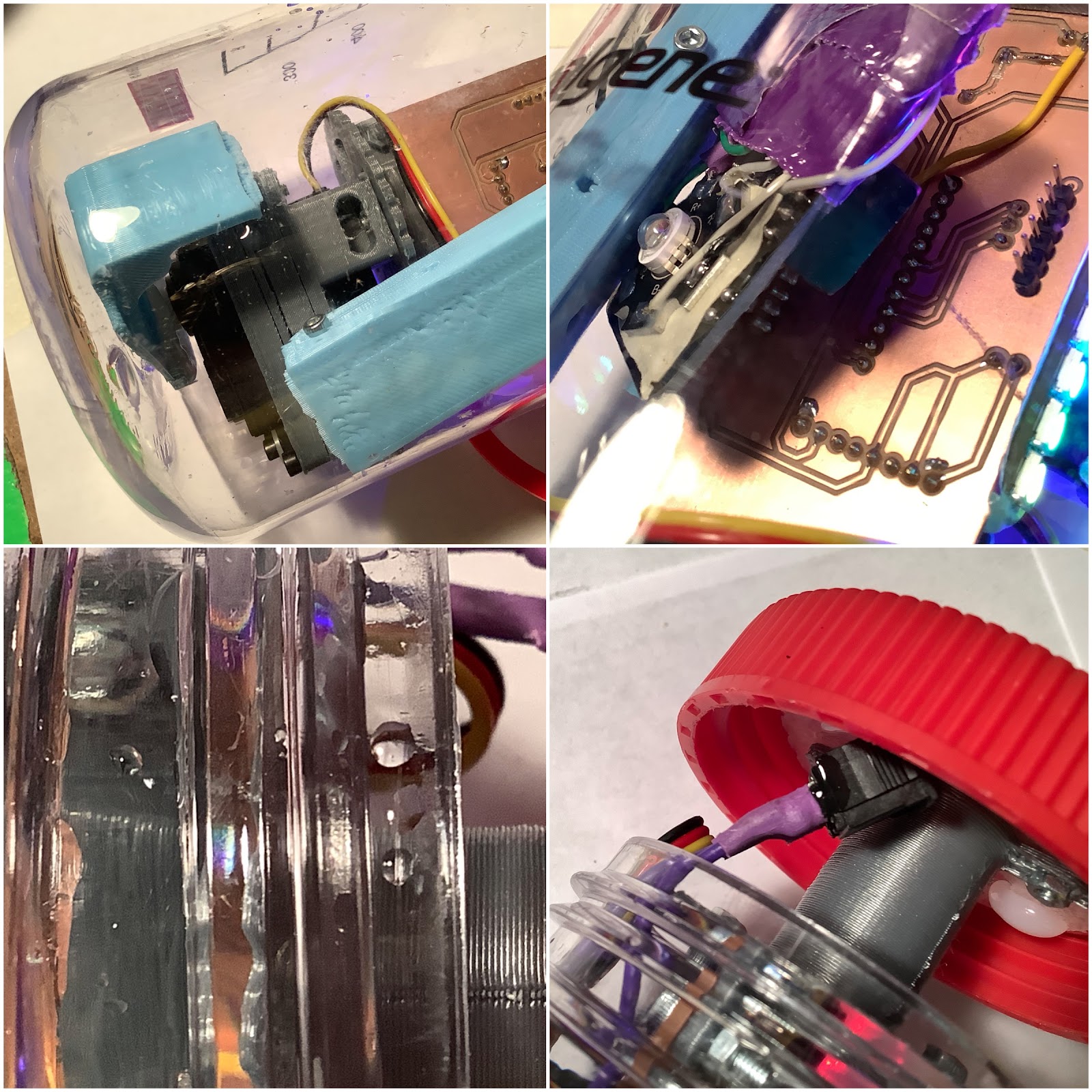
---------- more ----------Here were the fixes made to the board. For the servo traces, used some resistor leads to extend from the servo header to the traces that were not broken. Also added hot glue.
Here was the complete list of fixes:
The good news is that on setup, everything was functional except for the Neopixels. The important part is that the wiper is moving!
The first error that occurred was when the lid cap separated from the enclosure.
The trouble with getting it to sink to the floor still existed, it was even more-so with the faster current yesterday.
Here is a look at seeing the internal wiper moving:
The external wiper regularly disconnected because the internal wiper was moving across the LiPo battery. This distance was too much for the field of the magnets to reach the external magnets. It was interesting to see some sand near the magnets.
The organic matter suspended in the water was moving around faster today:
Here’s what it looks like when launching the buoy into the water with a pendulum throw:
And from the buoy cam:
Here is the internal wiper still moving at the conclusion of the test:
Here are the learning lessons from this test:
What worked
- Servo motor was moving
- New end cap design worked
- Two bags: wet & dry
What didn’t work
- Trying to get the buoy to stay underwater, especially in this faster current water with taller waves
- Neopixels didn’t light up
- External magnet wiper kept falling off and becoming lost (it was retrieved though)
What needs to change for future version
- Need a better homing sequence of the servo
- Battery gets in the way
- Need a string on the magnet piece to make sure it doesn’t go far away if disconnected (eventually make this a captured piece design)
- Better attachment for lid cap piece
- Record temperature, humidity, wind speed and approximate wave height for each test
These learnings were particularly useful for thinking about a version 2 design for testing. Additionally, the parts from the DesignLab were received yesterday (more on this later! Thanks @Giovanni !). This means we could test fastening the buoy to the spool box top plate, and also have better weights attached to the top plate.
As for the weights, there are multiple ideas. One could use weights, rocks, sand, water. For the water idea, the use of recycled bottles filled with water, attached to each of the end caps, could be a solution.
One of the key problems to solve will be getting the servo wiper positioned properly. When fastening, all the original positions are scrambled. Therefore, positioning will need to be adjusted dynamically. This could mean attaching limit switches to the sides of the battery which would be pressed when the wiper moves near it.
Guiding version 2 is the goal of being able to see and test the external wiper working in water.
-
Mech Update #14 - Test #01
08/28/2020 at 03:26 • 0 commentsNote: The content in this update was on August 25th.
Test #01 is upon us! Time to see what doesn’t work, and maybe there will be one or two things that do work.
Objective of the test
Test the functionality of the DIY Buoy B and understand the intricacies of getting it to work outside of the lab.
Read on for results of the test!
---------- more ----------Here is the preparation before the test. The designs for the two jigs for cutting in a previous update were used as end caps. These would have the ropes and feet attached to it. A single layer of duct tape was added to provide some grip. In the future, perhaps a rubber sheet can be used. As well, hot gluing the upper stage onto the underside of the lid!
Added the magnets to the external wiper, setting up the GoPro, glued Neopixels to the edge, and unsure at the moment what to do with the round circle piece. It will probably be cut in a future test. Rest assured there are no small fish in this testing location that can be caught by it.
At the test site, the preparation is to switch the device on, then fasten the lid. Fastening the lid is challenging because of the twisting that the wires internally undergo. Next is to tie the rope to the end cap.
This probably sounds obvious, the enclosure is buoyant. The majority of the time during the test was spent on trying to pile rocks onto the feet to keep it down.
Eventually, this worked a few times. What does the LED look like underwater? It’s still quite bright from the outside!
From underwater, the results were interesting too. The illumination showed the organic material suspended in the water. It is interesting, as from eyesight without light this wasn’t noticeable.
It was already plenty dark, so time to conclude this test.
Hooray! Test #1 complete. Here are the key learnings from this test:
What worked
- 3W RGB LED lit up
- Neopixels lit up
- Buoy is buoyant
- Enclosure remained watertight
- Lid piece remained attached
- GoPro captured test footage
What didn’t work
- End cap fell off
- Servo movement stopped
- Angle of GoPro changed
- Wires getting tangled during the fastening of the lid process
- Trying to hold the buoy steady underwater
- Figuring out where to put the wet equipment and dry equipment for transportation back to lab
What needs to change for future version
DIY Board and Electronics
- Move Arduino Pro Mini closer to edge
- Neopixel and servo headers at 90 degrees OR more secure connection (hot glue)
- Move capacitor in front of Neopixel header
- Check the attachment of the board? Looks like it was on a small angle
- Open notches on the upper stage piece to allow the wires to come through
- Figure out how to do wire management on the servo wire
- Future: Eventually additional sensors
- Future: Magnet sensor on top lid to activate program
Enclosure
- End cap needs to hold stronger
- Add teflon tape to the threads of the Nalgene bottle
- End legs need corner trimmed for enclosure to go through (new end cap)
- Holder needs space for enclosure to go through (new end cap)
Operations
- Have one bag for wet, one bag for dry, and bring a towel
- Test before sundown
Here’s a look at some of the pieces that did not work. Keep in mind, the enclosure was dropped from ~15cm onto a rough surface. Some of the damage may have been caused by this. The servo horn broke, the super bright lights board jumped off the connector. There was evidence of moisture on the threads, and one drop on the switch (the drop on the switch is undetermined if it was during the opening process).
As for the servo not working, the cause was that the traces were ripped from the board. This was likely caused during the setup process of twisting the lid and the wires snagging on each other, causing tension.
It is interesting as I haven't seen this error before, but it makes sense as to why it can happen.
-
Mech Update #13
08/28/2020 at 02:53 • 0 commentsNote: The content in this update was from August 22nd.
With time getting closer to the deadline, the pressure is ON to start testing something. The plan is to make a DIY Buoy B with some supplies here, in order to test some of the mechanical and design elements. As a treat, we will also test some lights - this will help us understand if it can be used as an illumination source for a camera monitor.
This was such an exciting moment! At last, all of the electronics are fully enclosed and the wiper is moving!
Read on for the steps that lead to this moment and to see the LED shine!
---------- more ----------Here’s the updated internal wiper moving:
The alignment has been improved to be closer to the center:
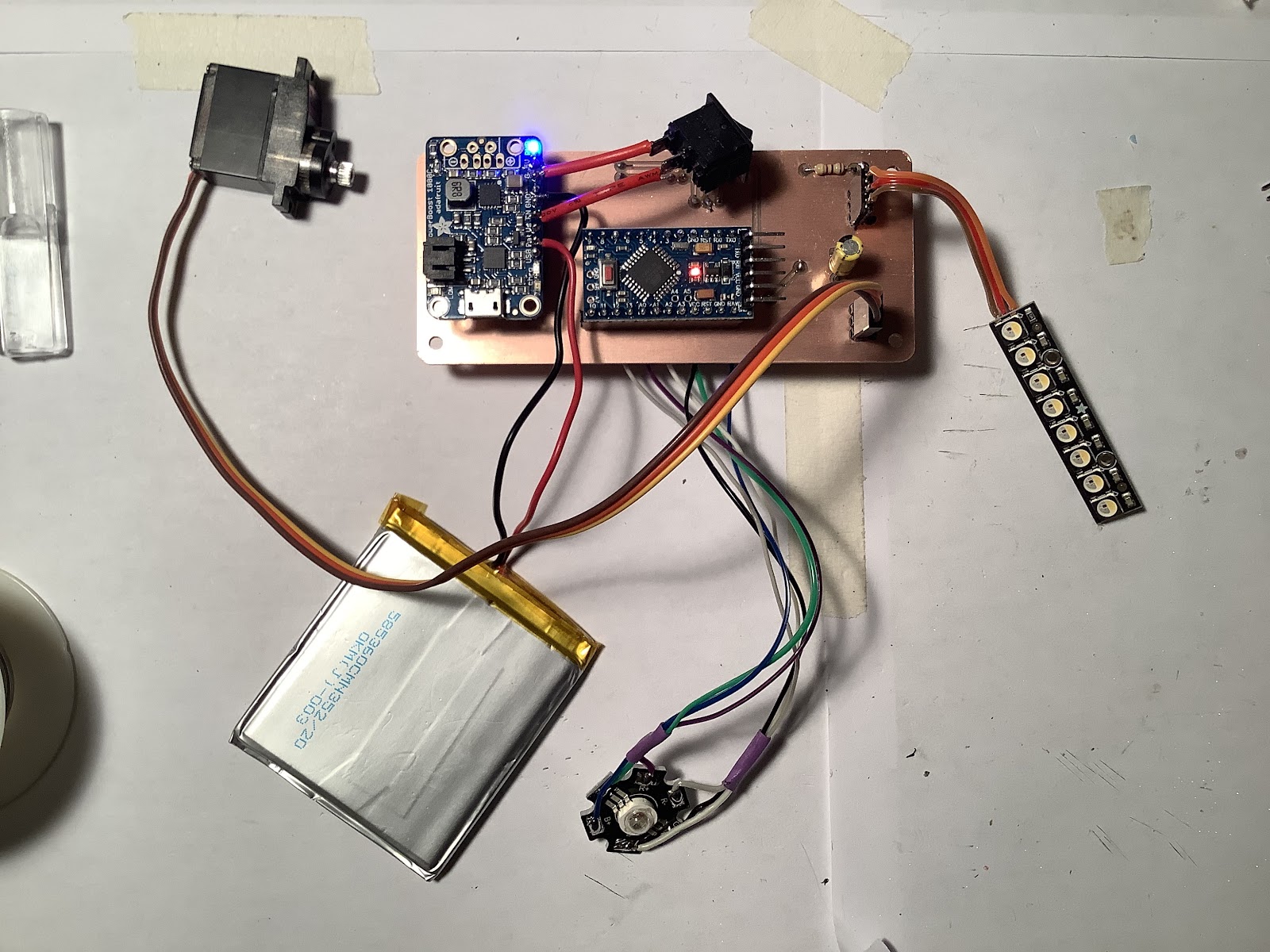
The DIY Buoy B will use a simple Arduino Pro Mini, the Robot Missions Super Bright Lights board, a 3W RGB LED, a Neopixel strip, a servo, and an Adafruit PowerBoost 1000. The battery will be a 2000 mAh LiPo. This is all attached to a double sided copper clad DIY circuit board:
The above image shows the process of making vias. Since this is not through plated, spare leads from resistors and the like are used to go between the two layers.
Next up was to scavenge some parts from old projects!
Here’s the board when populated and testing underway:
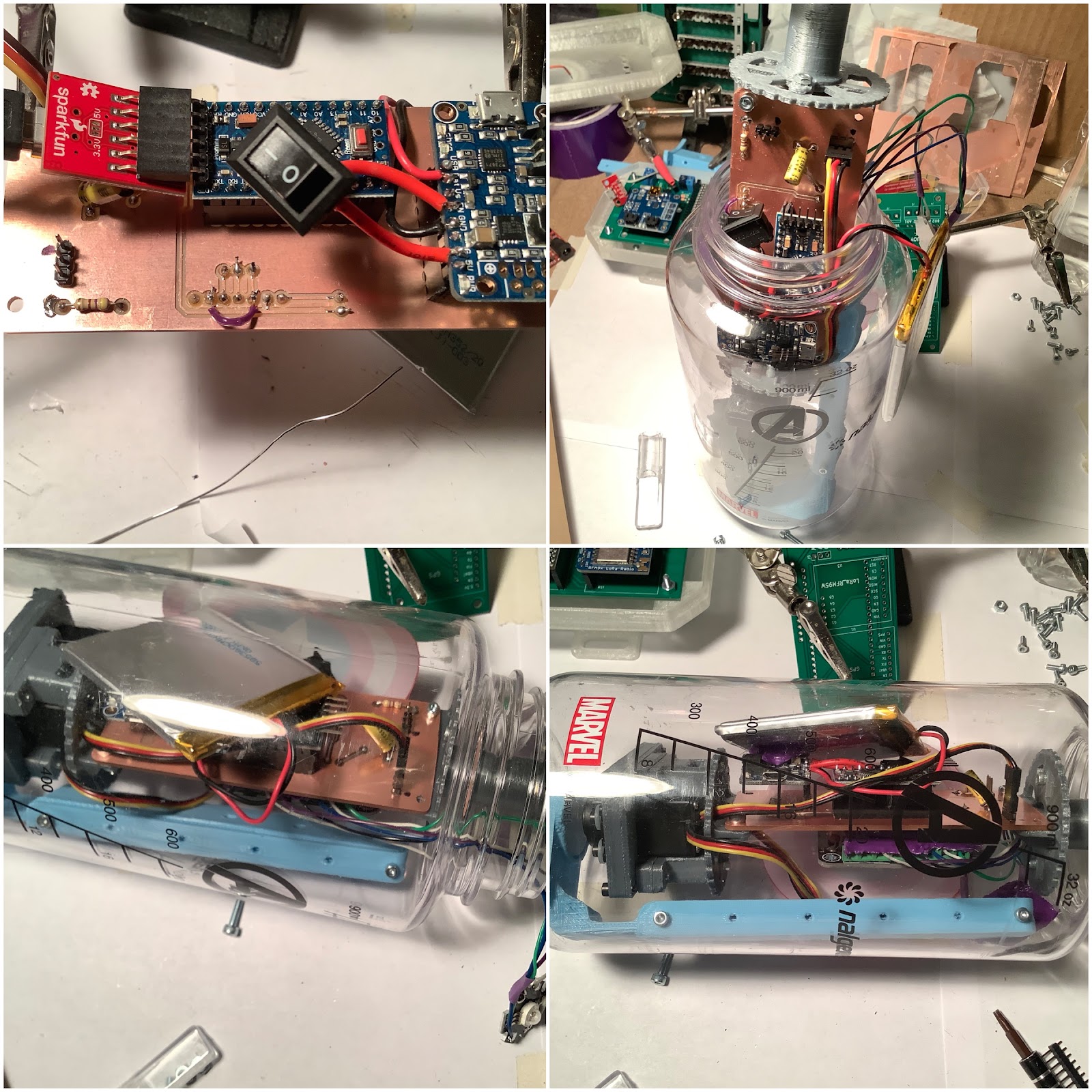
Test inserting it into the enclosure was a great experience in how horrible it went. There were many challenges and it needs a better design. Fastening the lid was the most difficult part, since everything rotates when doing so.
The battery placement works well when it is placed near the top of the enclosure attached to the inside:
The wires for the super bright led also have duct tape to manage the cables:
During the install, the servo has to be aligned so that the servo horn faces the opposite side as the battery. This means that with the range of movement, the internal magnet wiper should not move close to the battery.
Hooray! Everything is finally fully enclosed! Here’s what it looks like with the leds:
From a bench test, the light seems quite bright! However, we can’t make assumptions about a bench test (TRL 4) versus testing in a relevant environment (TRL 5). This is why we will test!
A few fixes were needed on this iteration. Namely, the Neopixels were attached directly to Vbat. This wasn’t good in terms of being able to switch off all the power. The fix was to change this to Vcc. The signal to the Neopixel still worked fine, without a logic level shifter to 5V.
Other changes included making the wires to the switch longer, and adding a detachable header connector for the battery. Oh yeah, and thanks to the PowerBoost having reverse polarity protection… oops! Everything still worked. :)
2021 HDP Dream Team: EJA
Learn more about Team EJA's intelligent buoy, and how their solution will help the global fight against ghost gear.