Time for another experiment for magnetic coupling between the internal and external of the enclosure.
This experiment differs from the first in two ways:
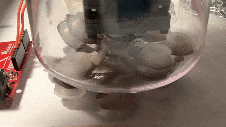
By using magnets attached to a piece of paper, glued onto the servo horn. This is to mimic the flexibility of a sturdier material that could be used, such as Delrin or thin HDPE, or TPU / TPE flexible 3D printing filament. The idea is that the force of the magnets would bend the material to make the closest contact possible.
By using magnets around the circumference in that plane via ‘petals’. Since the material is flexible, the petals can bend on installation, allowing it to fit through the narrow enclosure opening.
The hypothesis of this experiment is that the holding force will increase given the better contact between the internal and external magnets because of the flexible material.
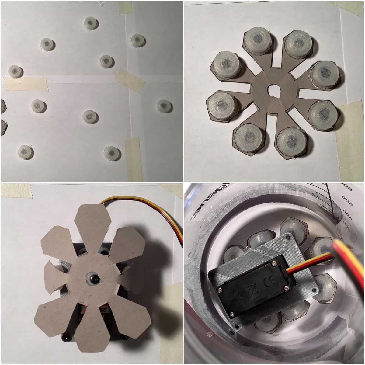
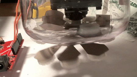
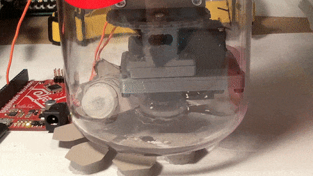
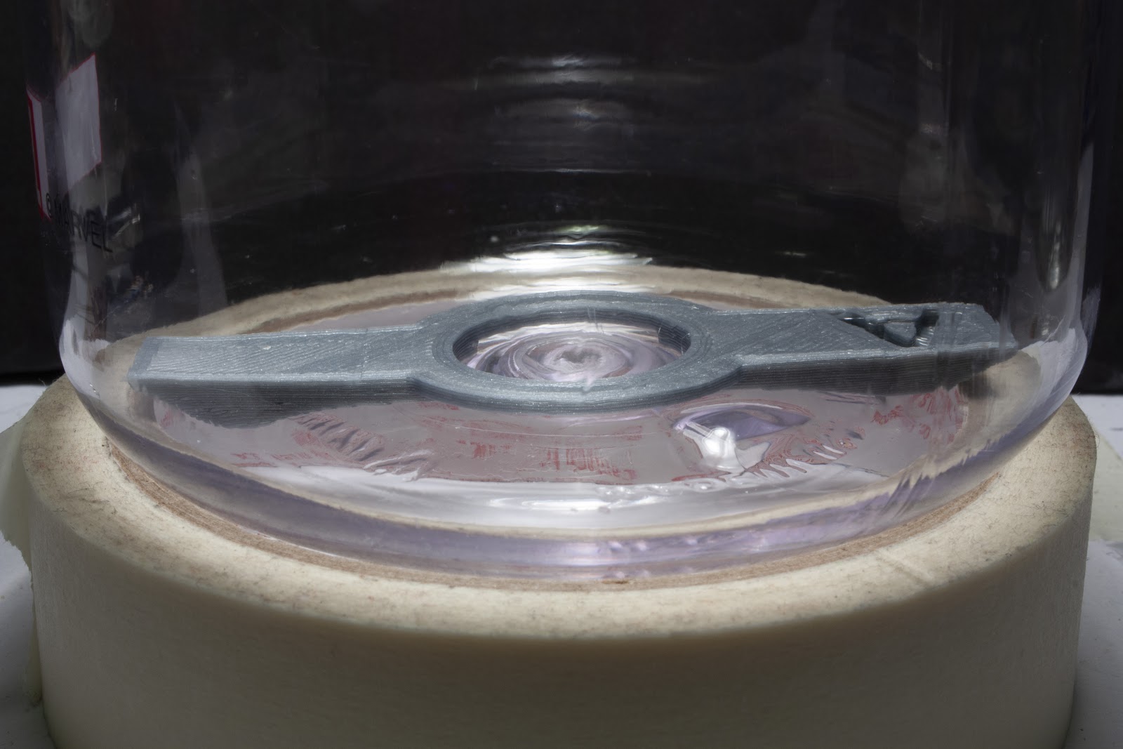
Here is how the experiment was constructed. Magnets were enclosed into 3D printed ‘chicklets’. This was so that the hot glue would be attached to the enclosure and not stick to the magnets - as to ruin the dimensionality. These magnets then are glued onto a piece of cardstock paper. With some bending, it was able to fit into the enclosure. The magnets used in this experiment are the thin ones, at 3.175 mm tall. (We have alternate ones, at 7.65 mm tall.)
The results of the experiment disproved the hypothesis.
Here’s a look at it in action:
Read on for the rest of the method and discussion.
---------- more ----------
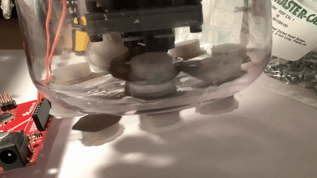
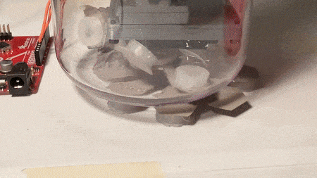
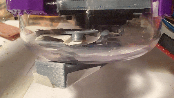
What you see here is as the servo is moving, the magnets on the petals are being attracted to the magnets on the servo block that attaches it to the rest of the assembly. There is some amount of force to keep the exterior magnets attached, sometimes.
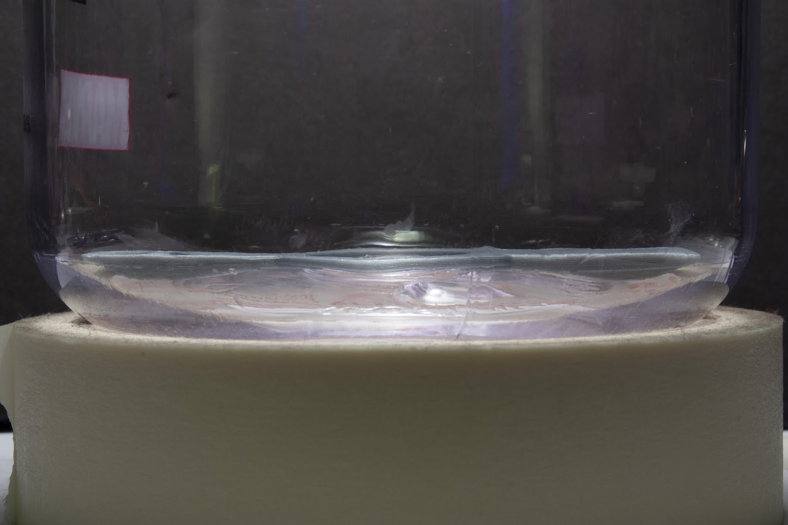
We can see the petals problem closer here:
Because of this position error, after some time the material will rip:
Although unexpected, the result does make sense. A different material could remove the risk of ripping. However, that would not address the problem that the holding force between the interior and exterior is weak.
The next experiment will use the taller, thereby stronger, magnets. The servo horn will only have 6 ‘petals’ on it, instead of 8.
There are other angles to be thinking about this problem:
Could the magnets be attaching on the other face of the cylinder?
Could it attach to a piece of metal, instead of to magnets? (Note, this might be tricky when keeping in mind the end environment (salt water)).
A bunch of magnets that are on the servo horn, and the exterior magnets are stationary.
It will be interesting to try the next experiment. The pieces are done printing, so it should be a faster time to test now. The deadlines are now urgent: boxes of 3D printed pieces and the fasteners need to be sent to Tobi and Leo from my place on Tuesday if we want it to get there on time.
PS: You may notice that there’s a jump in log numbers. #08 is about more 3D printing, testing, design - including the onboard gateway enclosure and a spacer piece for the buoy. This will be written down later — the results of the experiment were more important.
This update brings photos of the enclosure cuts and HDPE test coupons from the DesignLab, as well as the first version of the top plate of the spool box to be cut.
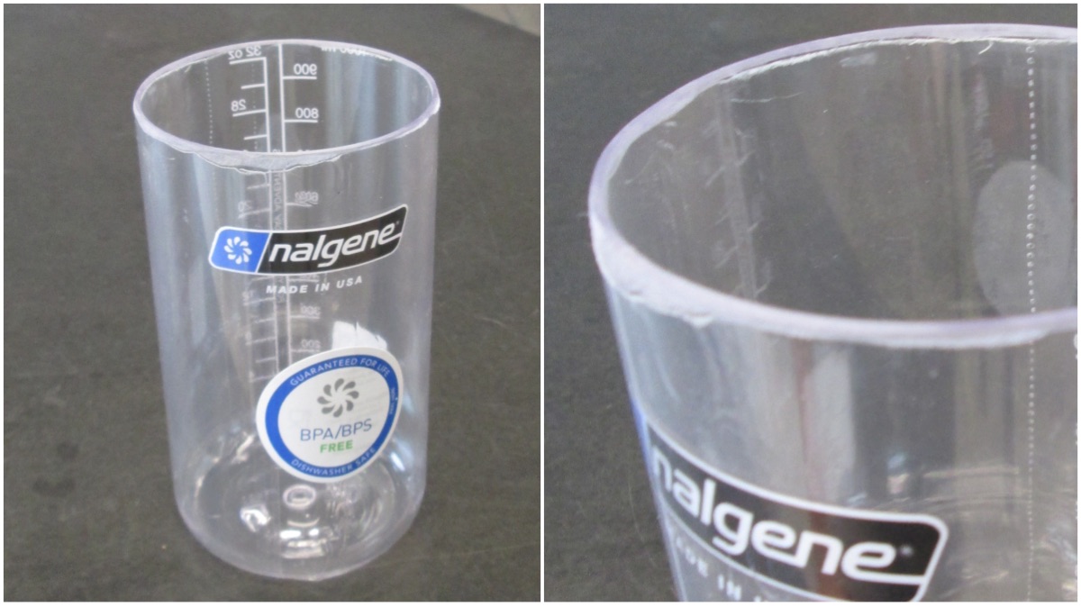
Here is the enclosure (polycarbonate nalgene water bottle) being cut. The cut location is just below where the curve ends for the start of the main width. Bruce from DesignLab made the cut:
Photo credit: Giovanni at the DesignLab
Read on for more about how it turned out, and see photos of the HDPE test coupons!
---------- more ----------
The nalgene was supported by a jig that we designed and then was 3D printed at DesignLab:
I wasn’t too sure how the tolerances were going to work, but it looks like it fit onto the exterior of the nalgene just fine. The cut was clean, though sanding proved to be a bit trickier. Here’s the result:
Photo credit: Giovanni at the DesignLab
This will suit our purposes very well! The larger enclosure will be for Buoy A, and we will be able to fit a Raspberry Pi with a camera on it for the fish monitor. There will need to be an o-ring cap designed for this, and tested, before electronics go inside.
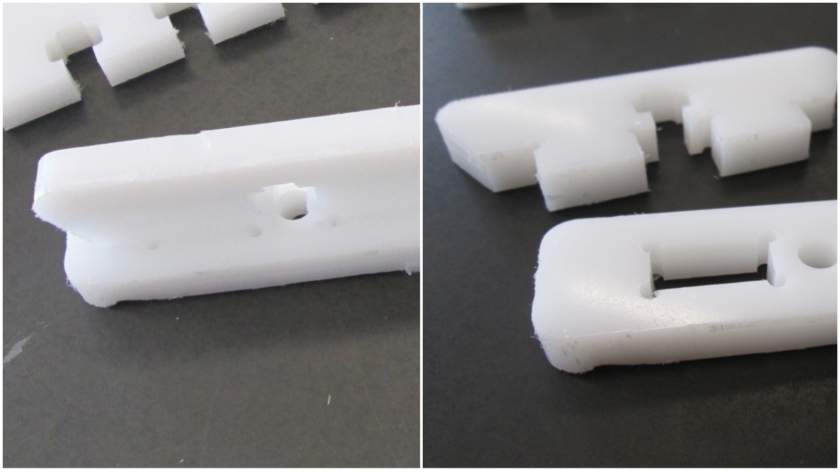
There are also the HDPE test cuts, these were milled using a 1/16” bit. The material is 3/8" (0.375”) thick; the bit didn’t reach the entire way. From the photos it looks fine for testing purposes. Check out the t-slot milled pieces.
Photo credit: Giovanni at the DesignLab
There’s extra space in the design of the t-slot, and it looks like the cut radius is fine on the piece without the dogbone. Here’s what the tabs look like:
Photo credit: Giovanni at the DesignLab
It fits! Glad that the alignment worked out. In this week’s design review, we were able to receive feedback on the design presented in update #06. Here are some of the changes that have been made:
Here is the new piece:
Of particular interest are the areas that stick out of the side. These are where the ropes will attach that go to the gear. The previous revision, the material was thin around this, and had some areas that were not very smooth in terms of curvature. The changes in the updated version reflect this. Additionally, repositioning of some of the fastener areas changed to provide nicer spacing between the countersink area and the cutout.
That’s all for this update. After update #06, the priority was re-evaluated again to work on the design pieces for the buoy. The strategy was then pivoted to allow for extra time designing and testing the pieces properly. More about this in a future update #08.
The top plate design was sent to Giovanni @Giovanni and Bruce today, so it can be milled on Monday or Tuesday. The circuit boards are somewhere in Ontario, however not arrived in this city yet. Shoutout to Bruce @brucejdii for his time and effort fabricating these pieces!
The next steps are (...were) to work on the design for the buoy and 3D print those pieces. Following that, for the spool box the next steps are to complete the design for the other sides, and the spool and sleeve bearing itself.
There are different free sources of Official Nautical Charts, usually each country provides the official charts for its territory, but in some cases there is one source for a group of countries. These sources usually store the nautical maps in vector formats, such as ENC and RNC.
Electronic Navigational Charts (ENC) are vector data sets that support all types of marine navigation. Originally designed for large commercial vessels using a sophisticated navigational computer called an Electronic Chart Display and Information System (ECDIS), ENCs are now also being used on simpler electronic chart systems and “chart plotters” on many types of ships and by recreational boaters [NOAA ENC].
Raster Navigational Charts (RNC) are vector data sets used for marine navigation.
The following table shows some of the Official Nautical Chart Sources:
South China Sea region: Brunei Darussalam, China, Democratic People's Republic of Korea, Indonesia, Japan, Malaysia, Philippines, Republic of Korea, Singapore and Thailand
There is an option for both online and offline server, but the offline version is more realistic since internet access would not be available most time
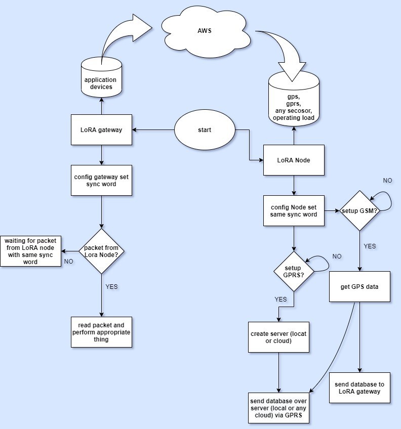
1. LoRa Gateway
Broadcast Local Server to connect with mobile devices
Users can connect through WiFi local servers to check data & can operate Motor, set the timer etc
Send request to connect to Node LoRa device
Receive GPS data through LoRa from Node LoRa Device.
Save previous GPS data received from Node Device (with time stamp)
Motor control button on local server (Can be operate by Mobile Web Browser)
2. Lora Node
Receive GPS data and send it to Gateway LoRa (if connected).
Store previous GPS data (if LoRa not connected)
Have the option to send GPS data to AWS Cloud using GPRS (only if LoRa is not present).
Will receive Motor control command from Gateway (only if connected with LoRa)
Have an option to send the last known Location on registered Mobile number through GSM if Lora Disconnects for “X minutes”.
General Firmware Logic
A. IF LoRa Connects (Gateway & Node)
Node will send GPS (live) data to gateway (every A Minute) (A is a condition that we decide on). Same time Node will save GPS data in its Heap Memory.
User can send set control command for Motor at Node.
User can connect and get Live GPS data on Local Server on gateway which is sended by Node.
GPRS and GSM will be powered OFF for saving battery life or put on sleep mode at some specific period.
B. IF LoRa Not Connected
Node will continue to save GPS data in its Heap Memory
If LoRa not get connect for X mins , last saved GPS location will be send to registered Mobile Number on GSM
The GPRS will send Live GPS data (or last known location data) on AWS.
This is still undergoing review with the team, additional firmware conditions would be added if need be.
Following from the previous update, design of the spool box and fabrication of the pieces in HDPE is one of the tasks that has its priority adjusted to be worked on now. The reason for this is to ensure there’s enough time to receive the pieces.
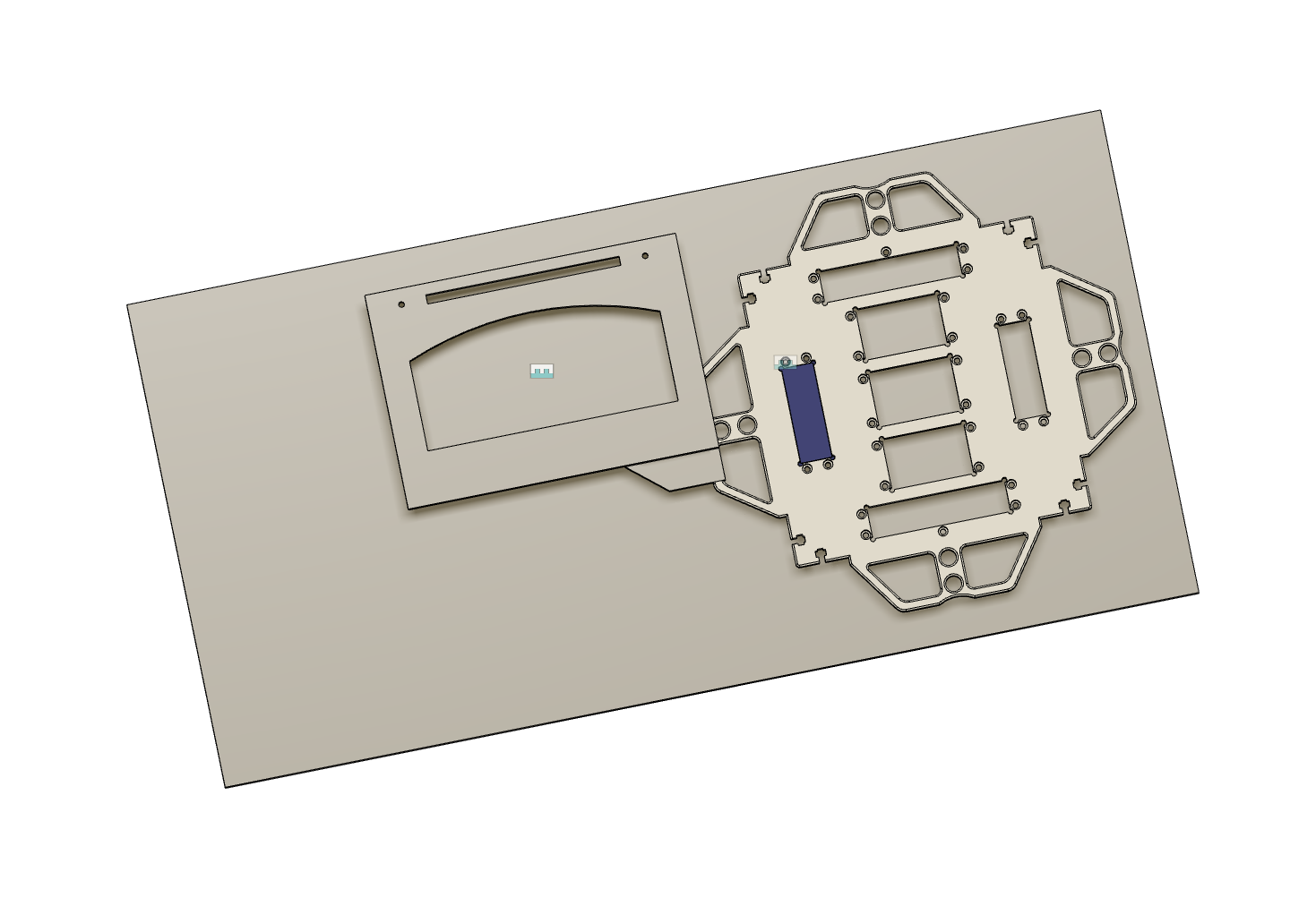
The spool box is what will house the spool of rope that attaches to the intelligent buoy. This in turn will latch onto the top of the spool box. Inside of the intelligent buoy will be the electronics - including a monitor to watch for surrounding fish traffic.
Here’s the start of the top piece:
Read on for more of the progress!
---------- more ----------
The first step was to design a few test pieces. These will be milled and we will then see the results to determine if any changes are needed. Thanks to Bruce and Giovanni at the DesignLab for helping with this.
Top left: Varying the spacing by 0.05mm each step, and included dog bones for 1/8" bit.
Top right: Same as left, but without the dog bones.
Bottom left: Tab and slot design
Bottom right: T-slot design for fastener
There was a lot of sketching to figure out exactly how the pieces will interlock together. This is usually easier to do on paper where you can erase quickly than CAD. There is an additional requirement - the spool boxes will need to stack.
Above: These sketches are figuring out where exactly the intelligent buoy will be placed on the spool box. The top middle was the idea that won because its placement would have the least likelihood of interference during the entry and descent in the water - as it has one ‘side’ ‘protected’ by the top plate. There will be 3D printed mounts, likely with magnets too, to help keep it in place.
Above: Now that the intelligent buoy has a place, it was time to figure out the other pieces and how they interlock. One of the tricky parts was bottom right, the fastening for the spool. Lucky for this, the head of the M6 doesn’t stick out when recessed into the material.
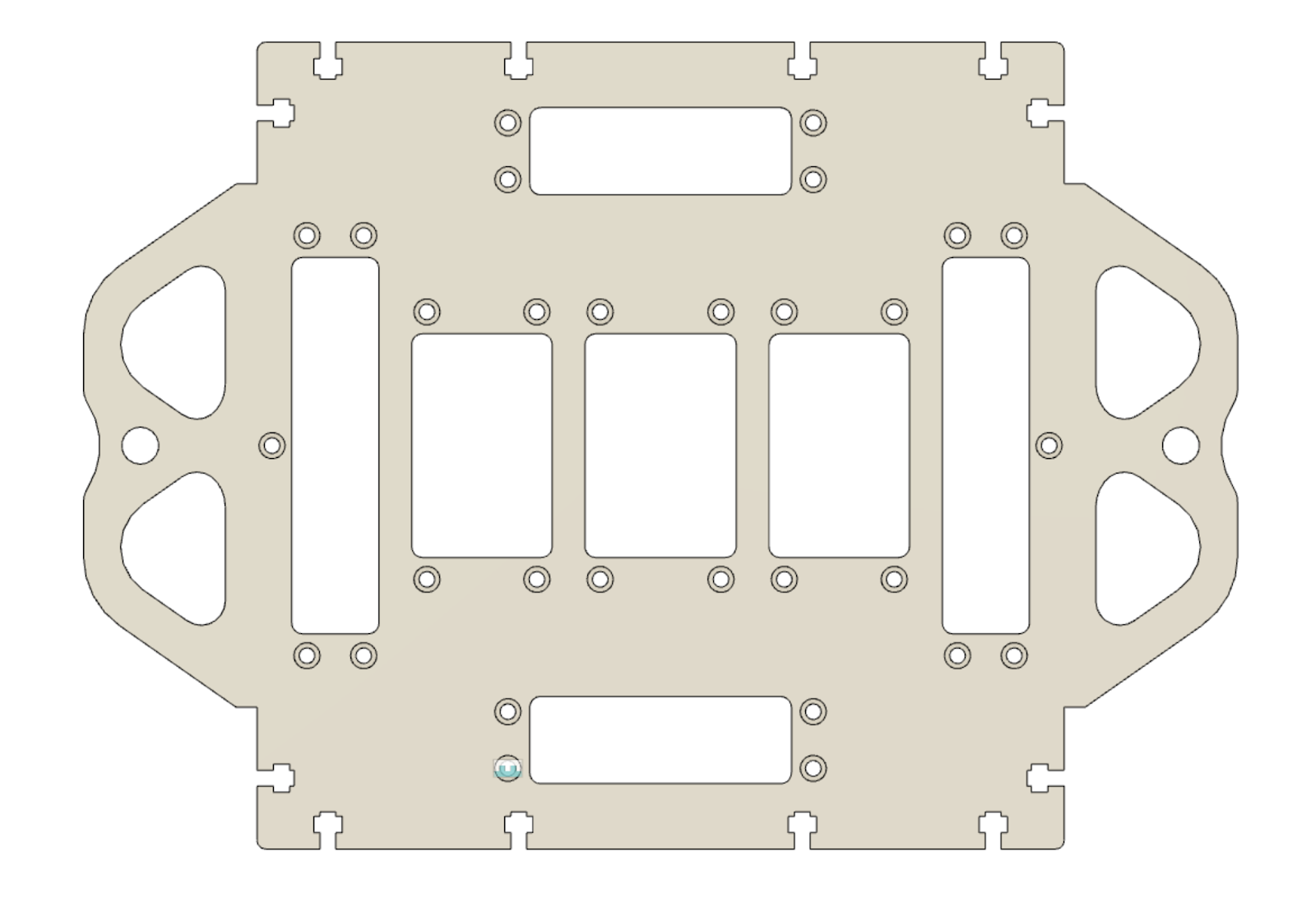
Here’s the start of the top plate of the spool box. This will be the fixed piece that sets the dimensions for the other pieces. Decided to go with the top plate for this, because it’s only dependency is the enclosure (nalgene bottle).
Deciding about the screws being recessed or not was a thought experiment. Here’s what the stack looks like. This shows the screw, a thin gasket, then a 3D printed piece that goes through the cutout in the HDPE. The purpose of the cutouts is for custom mounting brackets that will be specified later, and these can be iterated using 3D printing. Maybe a better way of doing this would be to leave it completely blank, then in real life use a drill to make the holes. However, the lack of precision irks me (not to mention I don’t have the proper setup for that task right now).
There’s a small error in the example above with the 3D printed piece. That will be fixed later, the purpose of this was to check the spacing and see there’s enough length on the fastener for a washer and hex nut.
Some progress was started on the front plate. The front plate can serve as a template for the back plate and side plates. Here’s how it looks with the two stacked. There will be 3D printed feet on the bottom that extend inwards to help with the stacking.
The sheet of HDPE ordered is 24” x 48”. We might need to order additional sheets. Also considering removing 2 of the rope handles from the top plate to decrease the size. Here’s how much space is already being used by these two pieces:
This is the progress so far. Tomorrow, (aka, today), we will hopefully see results from the first test cuts! From there we can decide what needs to change.
The next steps are to continue modelling the spool box. The Digikey order arrives tomorrow, and the PCBs have been shipped.
In the previous update we covered the first experiment results that did not work. In this update, we’ll take a step back in time to before then to show the iteration and prototyping that went into that experiment.
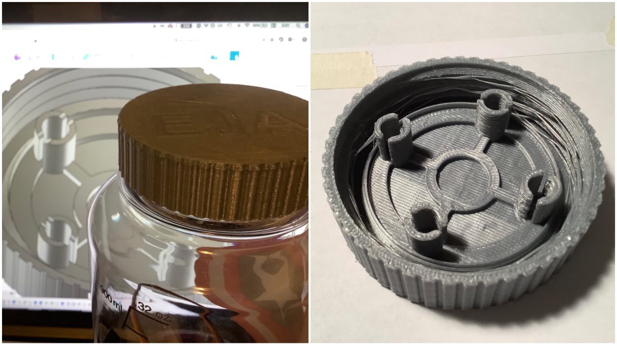
Internal Servo Horn
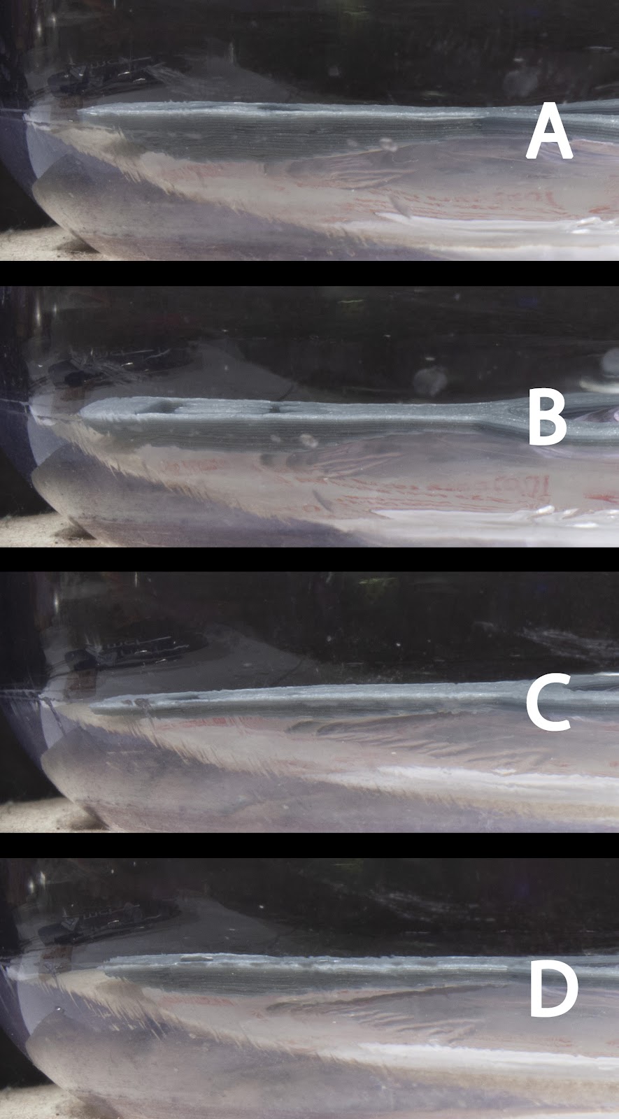
Let’s start with the internal servo horn. The internal servo horn will need to map to the curvature of the enclosure. To figure this out, I made a set of 4 experimental curvatures, printed them, and looked at how close their profile mapped to the enclosure. Here’s what that comparison looked like:
Read on for more!
---------- more ----------
From a different angle:
After comparing the images, the winner that seemed to be the closest was A. Here’s a look at it:
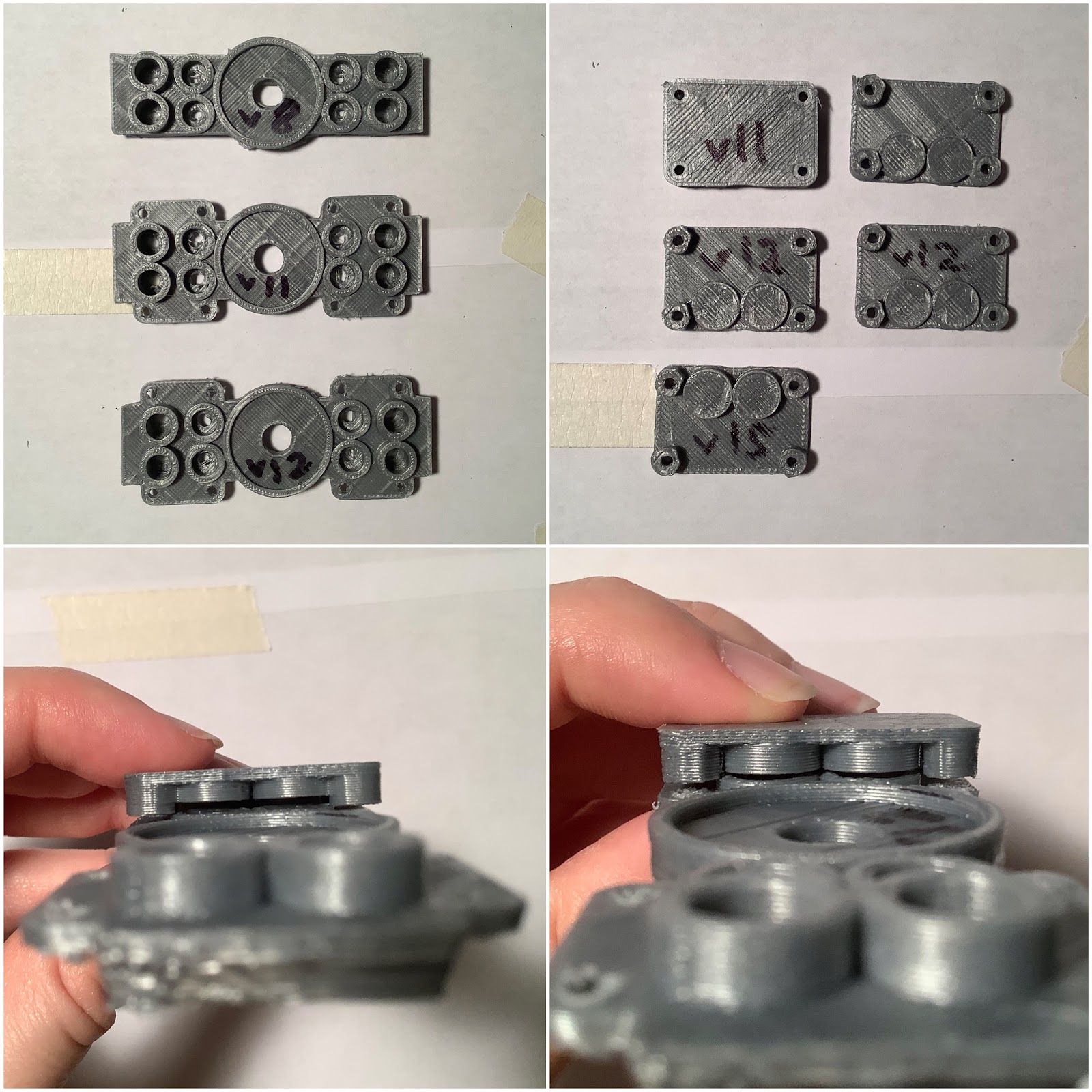
Now that the shape profile was chosen, design work could be done on adding the magnets. The first iteration included 4 magnets on each side, plus two additional on the other sides (sorry for the vague descriptive vocabulary there - see photo below).
However, this approach did not fit because the magnets on the sides increased the piece’s distance in Y axis to be tangent to the opening. These sides were then chopped off to verify that it would fit - and it did.
Above photo - Here are the next iterations of the internal servo horn piece. From v11 to v12, the thickness distance was increased as the magnets closest to the horn were not supported very well on v11. On the top right, this was running in to a DFM (design for manufacturing) issue. In this case, DFM via FDM 3D printing. The height on the CAD model of the two circles did not translate to reality (bottom left). After increasing this a bit, it then worked (bottom right). I believe the root cause of this is layer height resolution (0.3mm) and cooling (my printer has no cooling on the extruder). No big deal, just required a few iterations.
Above photo - Here’s the assembly of the internal servo horn. Tape was used on the magnets to prevent them from jumping during assembly (top left). Then, the covers were added (top right). The servo horn was attached to the servo’s servo horn using hot glue (bottom left). The reason for hot glue at this stage is because it was unknown how well the coupling would or would not be. If it were to be very strong, we would want the servo horn to disconnect from the servo instead of breaking the servo — specifically for the experimental stage. However, as we have seen, the results did not come close to having that effect. The external servo horn was then added, attached with magnets (bottom right).
External Servo Horn
The external servo horn required an abundance of patience. There were quite a few iterations required to determine the outer curvature of the enclosure (which was different than the inside). Here you can see the iterations and curve profiles:
The winning profile then went on to become the external servo horn. Here’s a look at how it maps to the enclosure:
In addition to this, some adjustments were needed on extending the distance internally to the servo block assembly. This was done by adding 5 mm to the end stage. In the future, I would accomplish this by sandwiching a wave spring in between stages to apply equal pressure to the internal servo horn contacting the bottom of the enclosure. That being said, looked briefly at the price of wave springs on McMaster-Carr and was a little surprised. Instead, a compliant mechanism can be designed and fabricated using flexible filament.
Threaded Lid
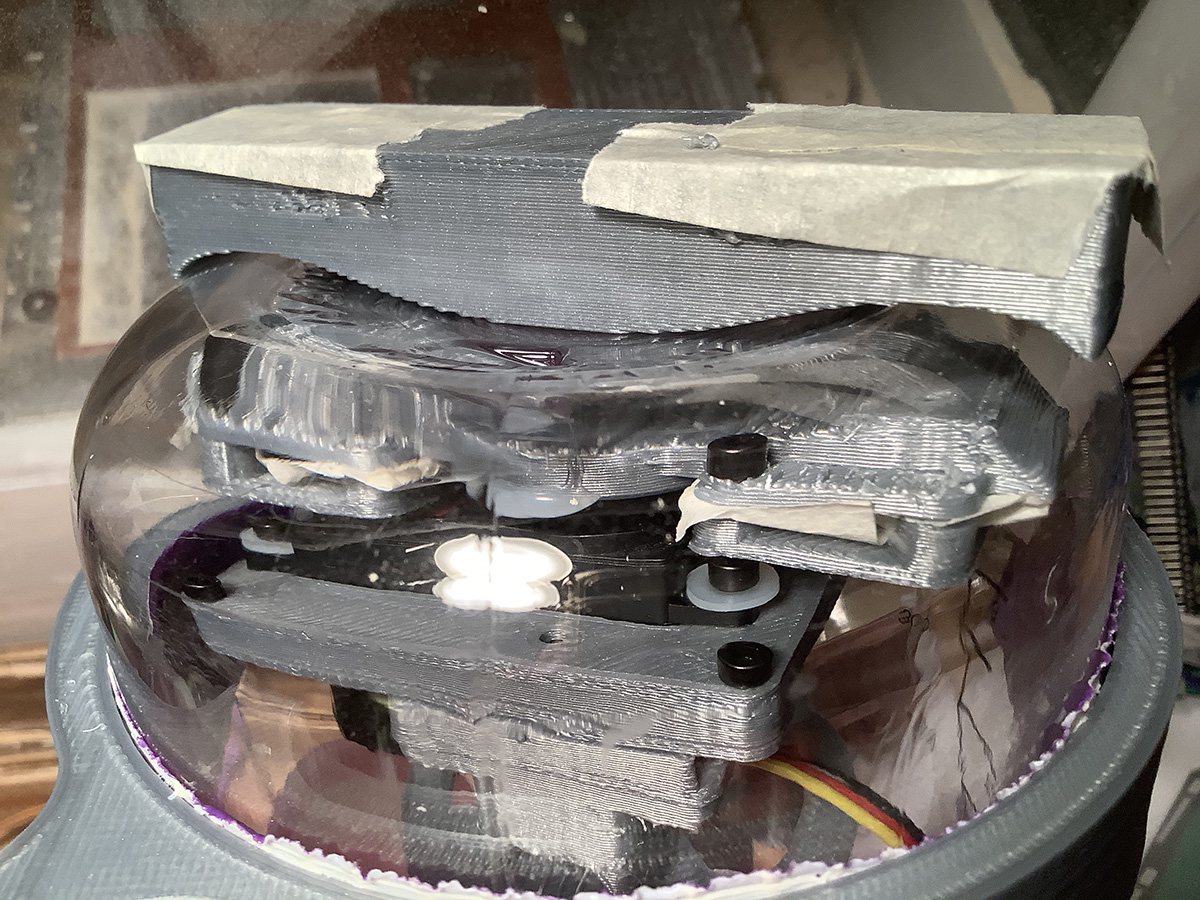
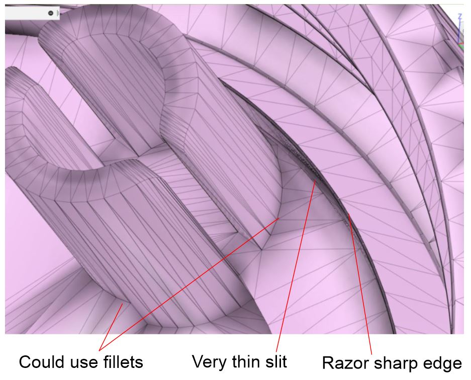
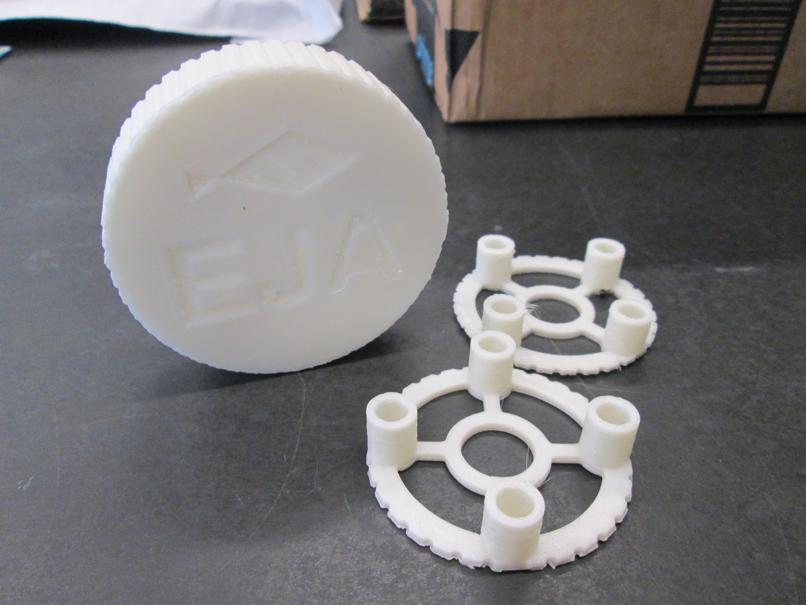
A prototype enclosure lid was printed. The design added the upper stage to it, and combined with the other mesh. The purpose of this test was to see if the threads work properly. They did! Next, it was sent to @Giovannis for printing on the Formlabs. That test will be to see if the lid can be waterproof. The design is built on Carlos Murphy’s Nalgene Cap from GrabCAD.
As you might have noticed from the above photo, the piece is not DFM - 3D printing. There are some improvements to be made now, because the original purpose of the test was to be a quick test print. There can be layer delamination on the vertical pieces that hold the wooden dowels, and fillets or ribs would assist. This was kindly pointed out by Giovanni with the results of the print at DesignLab:
What’s interesting here is that the ‘very thin slit’ is a remnant of the combined upper stage piece with the internal lid. The upper stage piece is undersized a little, so that with DFM - 3D printing, it will friction fit (eventually will use glue). So for this piece, that was noticeable!
Anyway, here are the first set of prints from the DesignLab! Those two pieces will be mailed out to Leo and Tobi soon!
Thanks, DesignLab! More to follow :)
Moving Forwards
Yes, it’s disappointing that the experiment results did not work this time given all the prototyping hours. It was an important learning experience to show just how crucial it is to try things as fast as possible and not be overly confident in early ideas as to invest the time into CAD and 3D printing.
Here’s the next thing to try. An attachment on the servo horn in a thin material (first paper, then delrin sheet). The magnets would be attached to this sheet. The sheet would be folded like origami, to fit into the enclosure opening. There are three candidate ideas for this design, as sketched below:
This will be prototyped quickly this week to see if a solution can be arrived at.
Next Steps
The next step is to take score of where I’m at right now with mechanical & design, and re-adjust the schedule and priorities where necessary. Further work on the experiment may move to a lower priority for now, as the spool box design and test pieces need to be completed for milling in HDPE at the DesignLab then shipping across the continent and into Canada.
Also, not sure if it’s worth noting, cleaned up some of the desk surfaces where I’m at. Always seem to find that helps to clear away the fails and promote trying new ideas. A blank slate, ready for work!
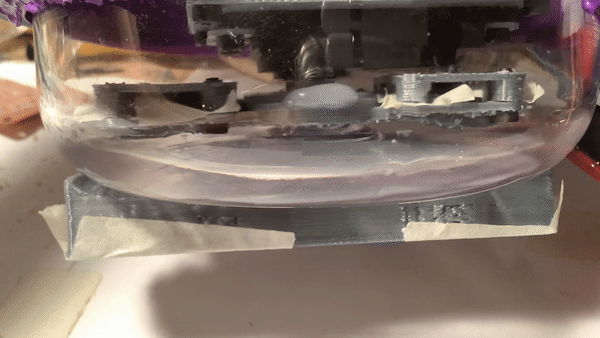
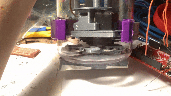
Preliminary results of the magnetic servo movement coupling test are here: The concept works. Here you can see the servo moving inside the enclosure, while a piece outside the enclosure is also moving.
The hypothesis was that this type of coupling mechanism would be strong enough to hold the buoy to the reel underwater, overcoming the buoyancy force, water currents, and the splash-down into the water.
HOWEVER, The observations with this test do not support the hypothesis. The coupling strength between the internal and external piece is weak. Minor resistance permits the piece to lose connection.
The original test that supported this as an idea to test was sticking two magnets to each other between the polycarbonate enclosure, which provided a strong connection. The setup in this test differed from the original test in that there's additional separation distance between the magnets due to the material thickness and air gap between the pieces.
What could have been improved about this test? The result could have been arrived at sooner. The prototype should have been made out of cardboard and hot glue. Getting too caught up in the iterations of the curvature of the bottom of the enclosure invested too much time in design and fabrication.
The next steps are to contemplate these observations and figure out ways of trying to improve the strength of the moving pieces. If no improvement is found, then it's time to move to a different release mechanism. Likely within the constraints of this enclosure. One idea could be a very strong electromagnet that would trigger a latch.
This is a quick update post to share these results. Over the past few days has been a lot of tedious effort on iteration of those two pieces. Will share all the photos of that in a project log later.
Here's an extra observation. In slow motion, you can see how the movement of the external piece 'catches up' to the internal piece. Interesting!
 Supplyframe DesignLab