 Supplyframe DesignLab
-
Onboard Gateway - Electronic Components
08/05/2020 at 15:24 • 0 commentsThe buoy transmits its position using LoRa, therefore it is necessary to create a device that the fishers can carry with themselves that receives the position data (using LoRa). This devices also creates a WiFi network and streams the data through it, a phone will be used to access this local network and visualize the data (using an app).
Similar to the buoy design, we considered different alternatives that were able to meet the requirements and then selected the best one, and selected the most appropriate ones.
Main Components
- Microcontroller: we selected the ESP32 DEVKITC 32D as the breakout board for this project because we need to create a local network and connect to external ones (WiFi). Similar to the buoy, we can have Over The Air (OTA) updates. Relevant alternatives that were considered: the LOPY IOT DEV BOARD.
- Communication: we selected the RFM95W LoRa Radio because it provides an acceptable coverage and the technology facilitates the creation of a network were different buoys are streaming their position.
- Battery Charger: we selected the USB LiIon/LiPoly charger. All the boards in the design can work with 3.3V, a 1 cell Battery (3.7V) will power the device. This breakout board was selected because it connects to the battery and the load. The board will charge the battery if it detects an external power source, and also power the load using the battery. Relevant alternatives that were considered: the USB / DC / Solar Lithium Ion/Polymer charger.
-
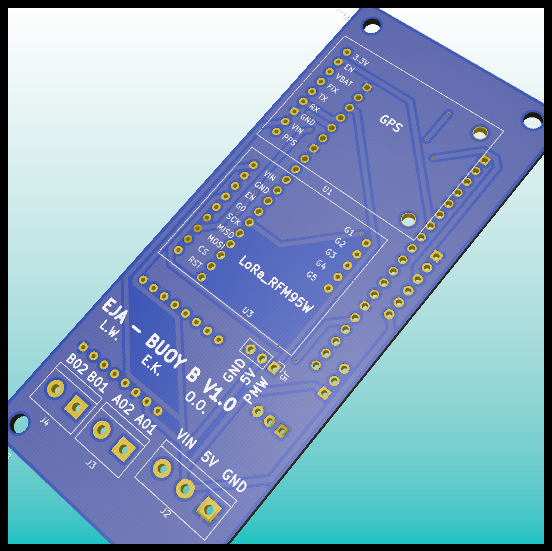
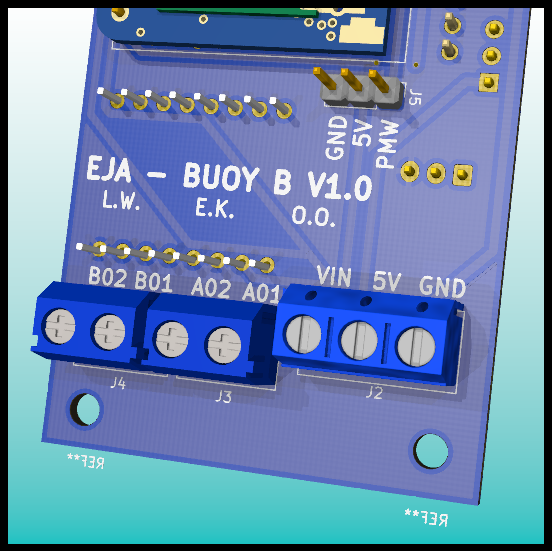
Buoy B V1.0 - Schematic and PCB Design
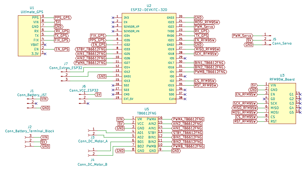
08/05/2020 at 14:04 • 0 commentsThe second electronic design for the buoy (Buoy B) will contain the following main components:
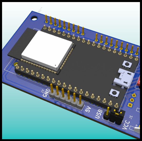
- ESP32 DEVKITC 32D
- Ultimate GPS
- TB6612FNG
- Servo connection
- RFM95W (LoRa)
Once we selected the main components we created a schematic and designed the PCB.
The main characteristic that differentiates the design of Buoy A and Buoy B is that the first one contains the GSM module, and second one doesn't have it.
Schematic
![]()
Bill Of Materials
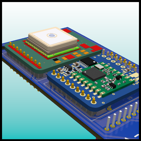
Quantity Name Description 1 Adafruit Ultimate GPS GPS Module 1 RFM95W LoRa Radio LoRa Module 1 ESP32-DEVKITC-32D ESP32 Module 1 TB6612FNG MOTOR DRIVER BOARD Motor Driver 1 TERM BLK 2P SIDE ENT 5.08MM PCB Terminal Block for the DC Motor 1 TERM BLK 3P SIDE ENT 5.08MM PCB Terminal Block for the Vin, 5V and GND 1 CONN HEADER R/A 3POS 2.5MM 7.4V 2 cell Battery Connector 2 CONN HEADER VERT 40POS 2.54MM Male Headers 1 CONN JUMPER SHORTING .100" GOLD Vin selector for the ESP32 1 GPS Antenna GPS Antenna 2 LoRa and GSM Antenna LoRa and GSM Antenna Since this is the first version of the design, we won't solder the breakout boards (GPS, LoRa, Motor Driver and ESP32) directly to our PCB (Buoy B), instead we will connect them using headers. Female headers will be soldered to the PCB and male headers to the breakout boards. The use of headers will help us to debug the design by connecting and testing one of the modules at the time. The following table presents the required headers:
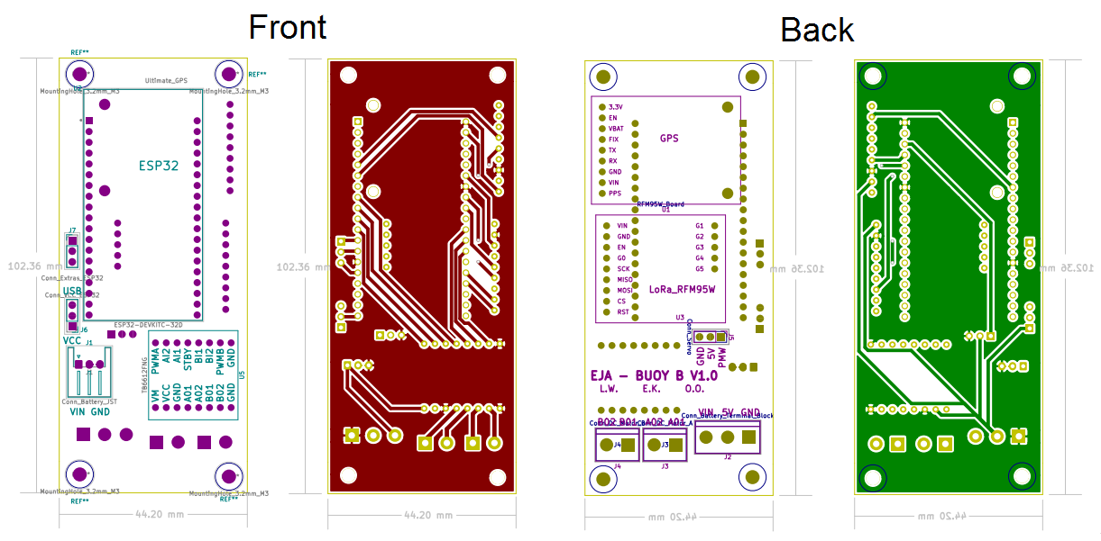
Quantity Name Description 2 CONN HDR 19POS 0.1 TIN PCB Female Header used to connect the ESP32 2 CONN HDR 8POS 0.1 TIN PCB Female Header used to connect the Motor Driver (TB6612FNG) 2 CONN HDR 9POS 0.1 GOLD PCB Female Header used to connect the GPS and the Lora Module 1 CONN HDR 5POS 0.1 GOLD PCB Female Header used to connect the Lora Module PCB Layout
![]()
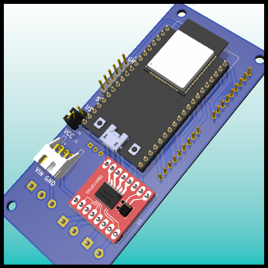
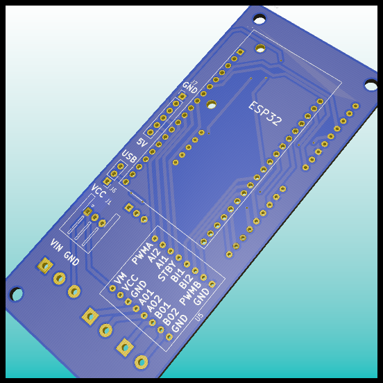
3D Model
![]()
![]()
![]()
![]()
![]()
![]()
![]()
![]()
-
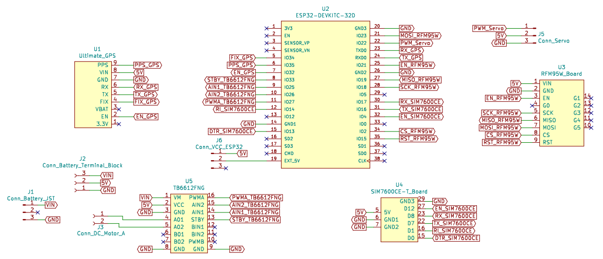
Buoy A V1.0 - Schematic and PCB Design
08/05/2020 at 13:35 • 0 commentsThe first electronic design for the buoy (Buoy A) will contain the following main components:
- ESP32 DEVKITC 32D
- Ultimate GPS
- TB6612FNG
- Servo connection
- RFM95W (LoRa)
- SIM7600CE-T (GSM/GPRS)
Once we selected the main components we created a schematic and designed the PCB.
The main characteristic that differentiates the design of Buoy A and Buoy B is that the first one contains the GSM module, and second one doesn't have it.
Schematic
![]()
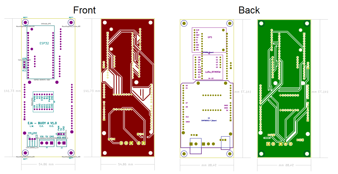
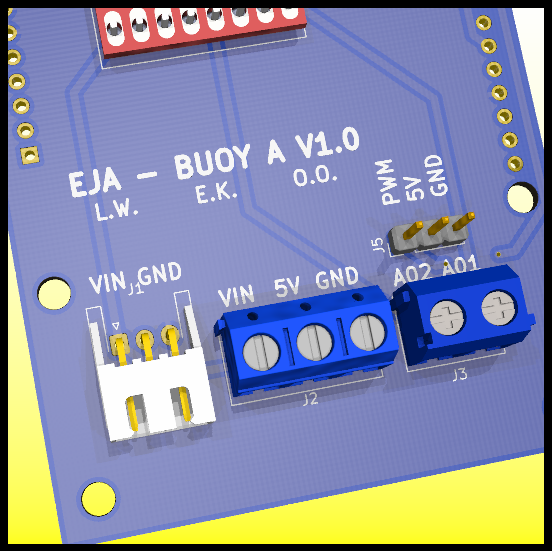
Bill Of Materials
Quantity Name Description 1 Adafruit Ultimate GPS GPS Module 1 RFM95W LoRa Radio LoRa Module 1 ESP32-DEVKITC-32D ESP32 Module 1 TB6612FNG MOTOR DRIVER BOARD Motor Driver 1 TERM BLK 2P SIDE ENT 5.08MM PCB Terminal Block for the DC Motor 1 TERM BLK 3P SIDE ENT 5.08MM PCB Terminal Block for the Vin, 5V and GND 1 CONN HEADER R/A 3POS 2.5MM 7.4V 2 cell Battery Connector 2 CONN HEADER VERT 40POS 2.54MM Male Headers 1 CONN JUMPER SHORTING .100" GOLD Vin selector for the ESP32 1 GPS Antenna GPS Antenna 2 LoRa and GSM Antenna LoRa and GSM Antenna 1 SIM7600CE-T 4G(LTE) Arduino Shield GSM/GPRS Module Since this is the first version of the design, we won't solder the breakout boards (GPS, LoRa, Motor Driver and ESP32) directly to our PCB (Buoy A), instead we will connect them using headers. Female headers will be soldered to the PCB and male headers to the breakout boards. The use of headers will help us to debug the design by connecting and testing one of the modules at the time. The following table presents the required headers:
Quantity Name Description 2 CONN HDR 19POS 0.1 TIN PCB Female Header used to connect the ESP32 4 CONN HDR 8POS 0.1 TIN PCB Female Header used to connect the Motor Driver and the GSM/GPRS Module 2 CONN HDR 9POS 0.1 GOLD PCB Female Header used to connect the GPS and the Lora Module 1 CONN HDR 5POS 0.1 GOLD PCB Female Header used to connect the Lora Module 1 CONN HDR 10POS 0.1 TIN PCB Female Header used to connect the GSM/GPRS Module 1 CONN HDR 6POS 0.1 TIN PCB Female Header used to connect the GSM/GPRS Module
PCB Layout![]()
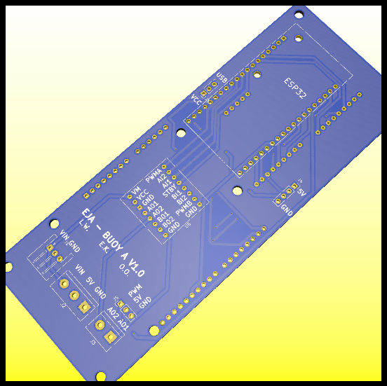
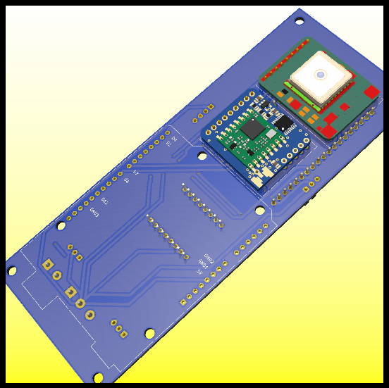
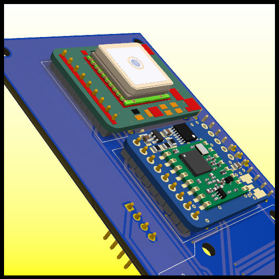
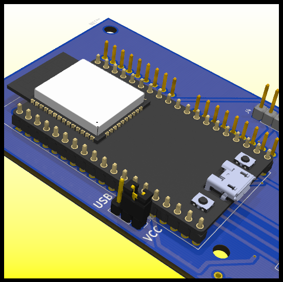
3D Model
![]()
![]()
![]()
![]()
![]()
![]()
![]()
![]()
-
Firmware setup process
08/05/2020 at 07:21 • 0 commentsThe bouy system consists of five parts:
- Motor controller
- Ultimate GPS
- ESP32
- LoRa RFW95
- SIM7600 (GSM Modem)
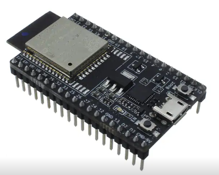
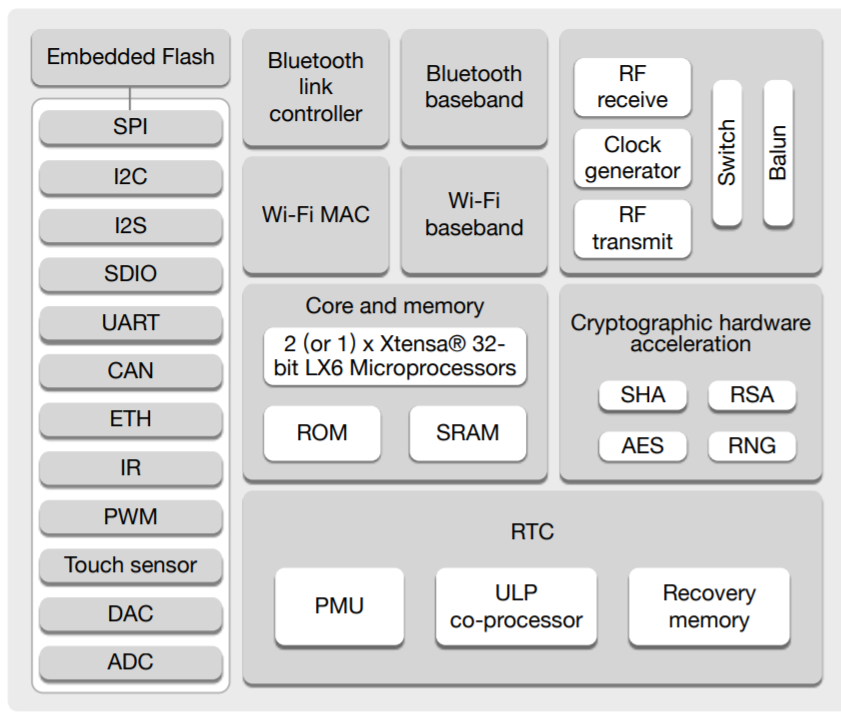
We have finally decided to go for ESP32 for the firmware interface for both the bouy and the onboard gateway.
![]()
This is an ultra-low-power solution designed for IoT applications because of its low power with a transmitting power of +12dBm.
![]()
For the purpose of our solution, we shall develop all the firmware on the ESP and the memory will be enough to serve for the Bouy and onboard gateway.
During the design, we shall develop the firmware code on Arduino IDE for coding flexibility among the team and for quick debugging.
The first test process is to check the network connection by interfacing the ESP with the GSM modem and enable the connectivity and then implement the GPS directly to the bouy.
-
Intelligent Buoy - Electronic Components
08/05/2020 at 03:58 • 0 commentsThe intelligent buoy requires position marking and communication. To accomplish those goals, we evaluated different alternatives and selected the main components in the design.
For the first prototype we mostly selected breakout boards to perform the proof of concept as soon as possible.
We considered different alternatives that were able to meet the requirements and then selected the best one, because of its features or the cost (we want to design low cost solutions).
Main Components
- Microcontroller: we selected the ESP32 DEVKITC 32D as the breakout board for this project because we wanted to perform Over The Air (OTA) updates. Having OTA can reduce the times that the buoy needs to be opened to access the electronics. The buoy needs to be waterproof, and will be sealed. Relevant alternatives that were considered: the LOPY IOT DEV BOARD.
- GPS: we selected the Adafruit Ultimate GPS. We found that it has been used before in buoys for position marking in the Open Source Ocean Data Buoy Project and the Drifting Buoy Project.
- Communication: we selected the RFM95W LoRa Radio because it provides an acceptable coverage and the technology facilitates the creation of a network were different buoys are streaming their position.
- Motor Controller: we will test servo motors in the release mechanism, and the ESP32 can create the required PWM. We also added the TB6612FNG MOTOR DRIVER BOARD as a backup plan, in case we need to use a DC motor instead of the servo motor.
- GSM/GPRS: we selected the DFRobot SIM7600CE-T 4G(LTE) Arduino Shield because of its global coverage and the possibility of incorporate 4G GSM at a relative low cost.
Considering the size of each board we realized that the SIM7600CE-T will probably exceed our width limits inside our current design of the buoy. Therefore, we decided to create 2 designs: the PCB Buoy A will contain the GSM board, and Buoy B won’t have it.
-
Mech Update #03
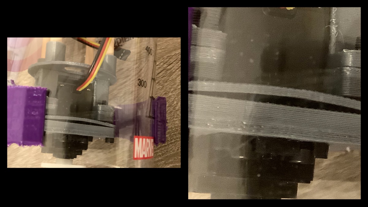
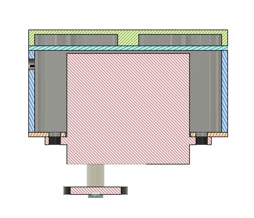
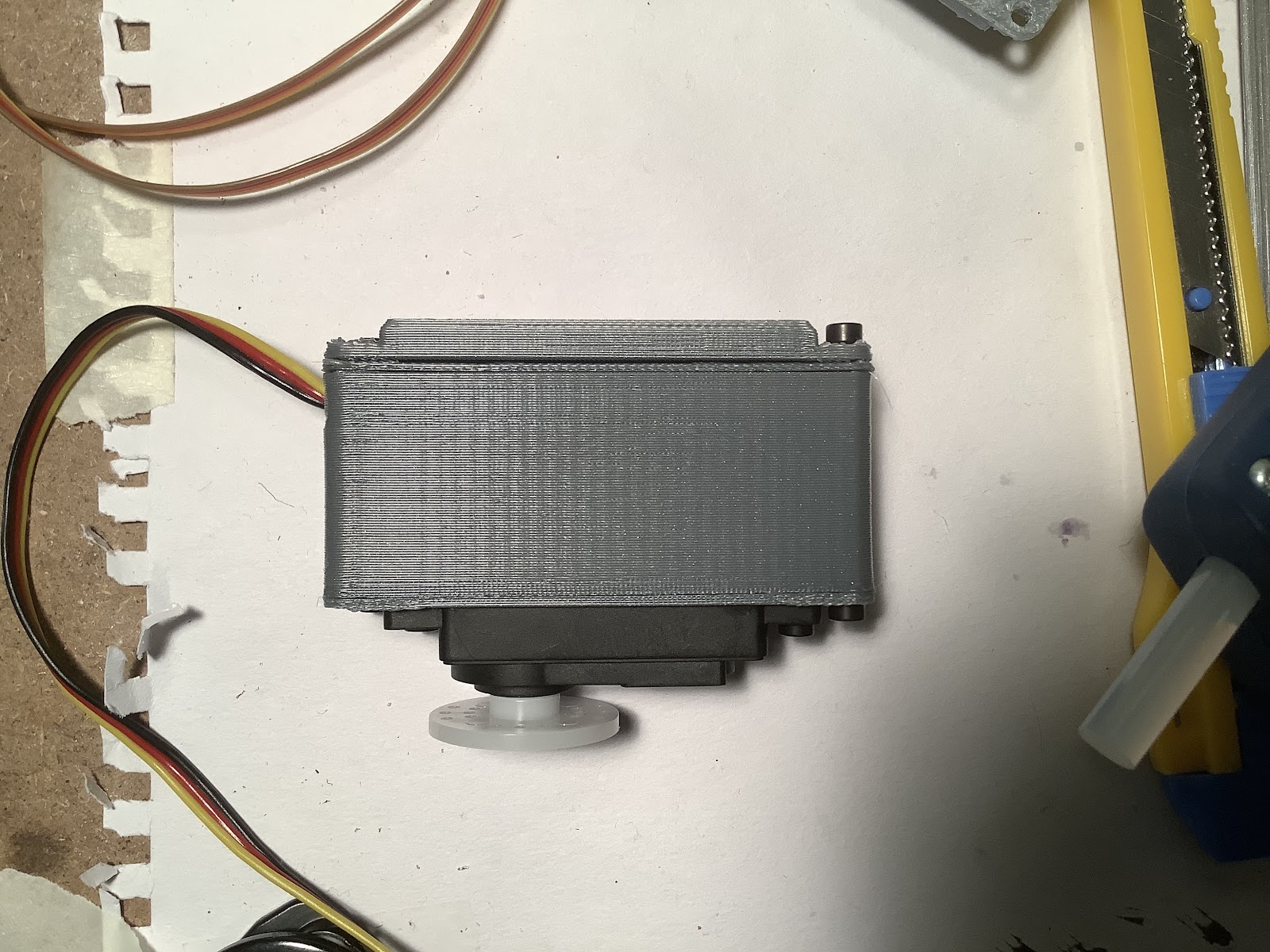
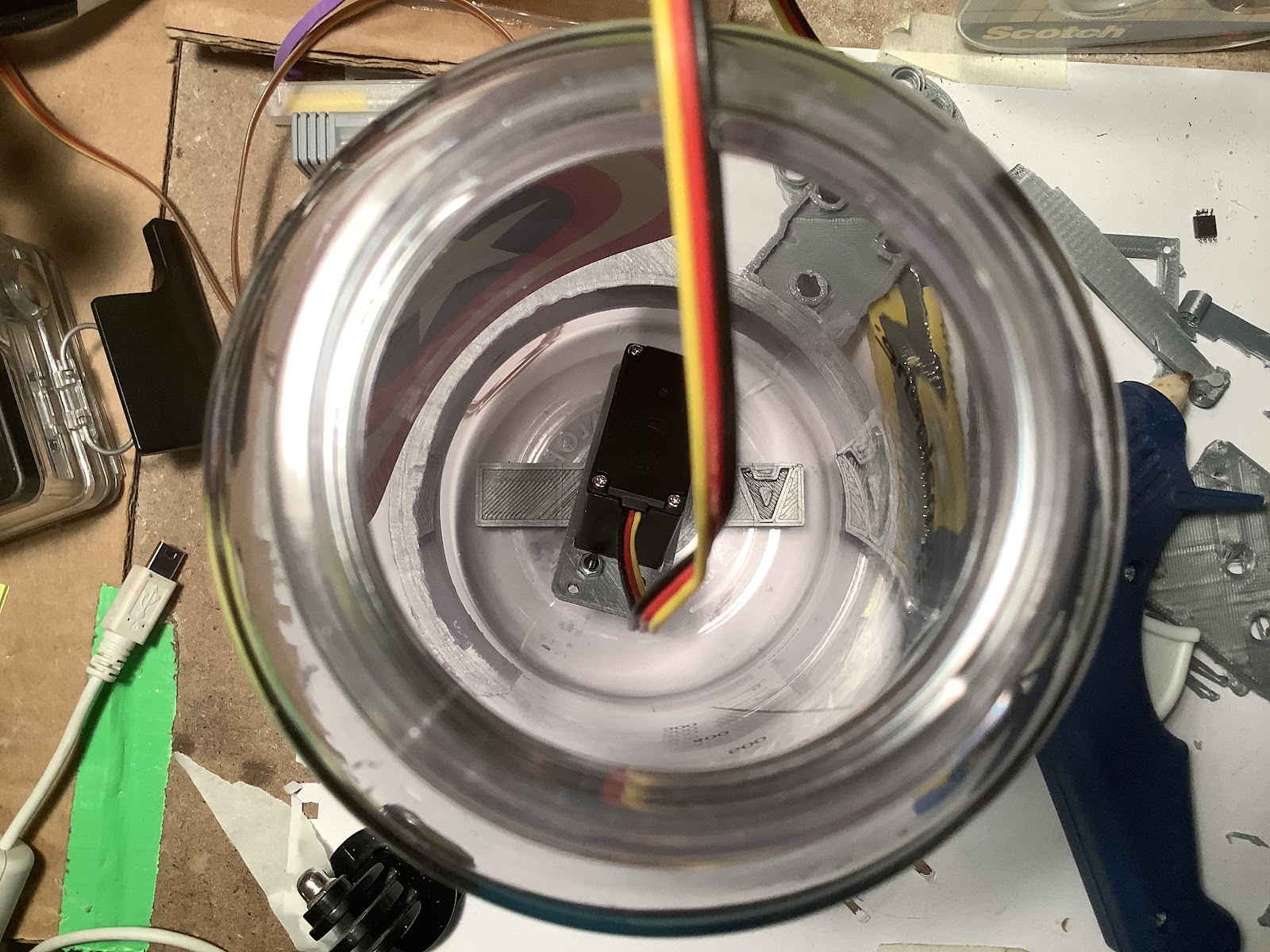
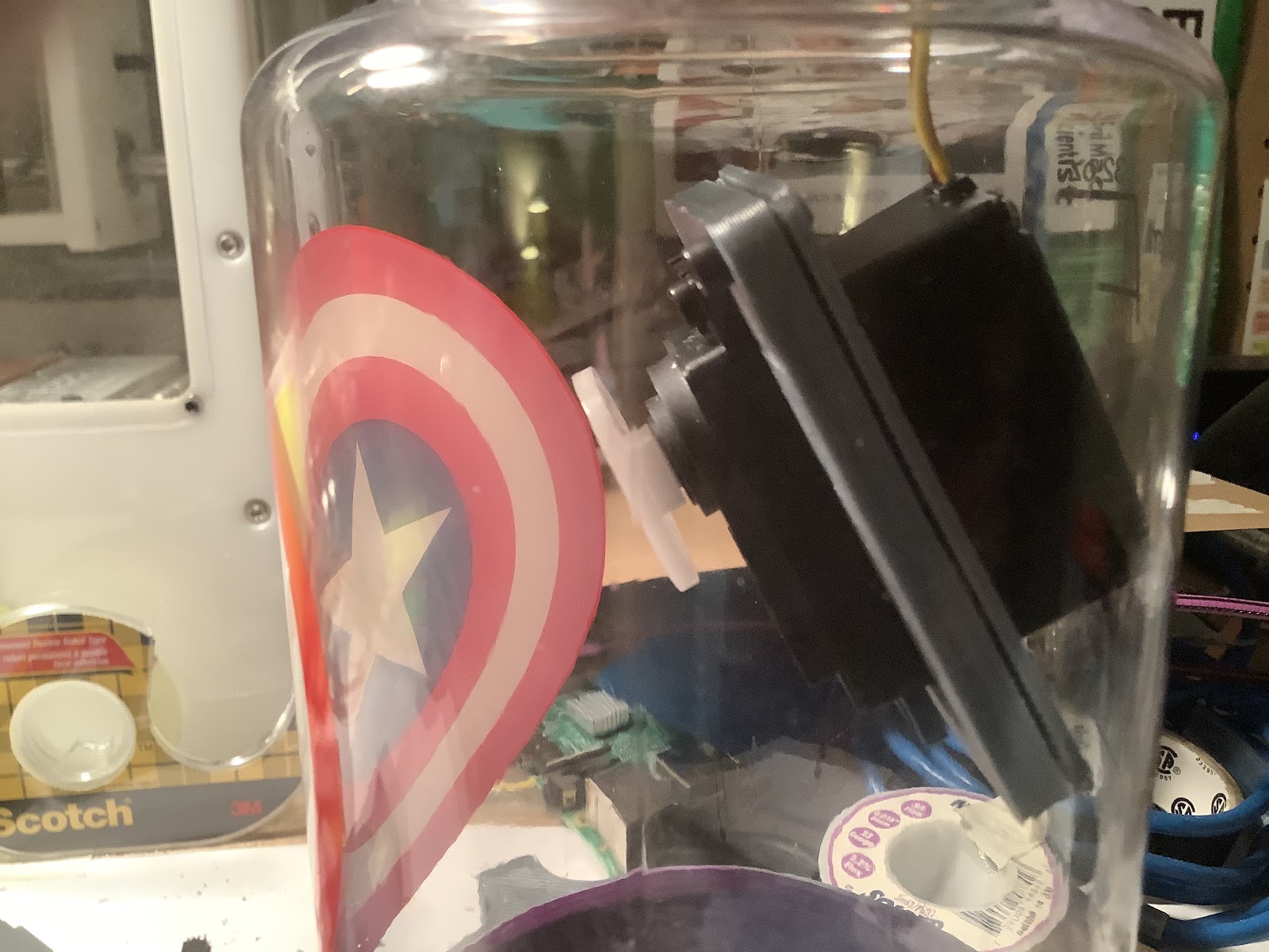
08/04/2020 at 07:42 • 0 commentsThe servo fits and the magnetic coupling attaches:
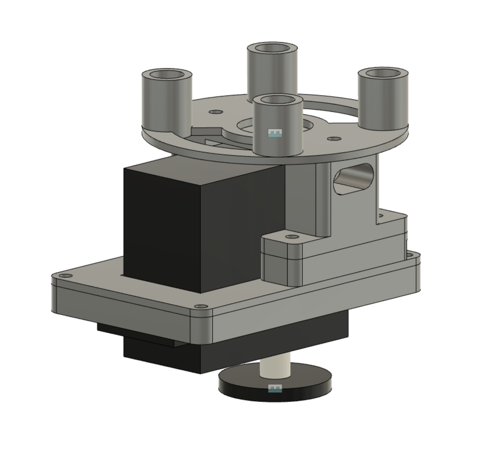
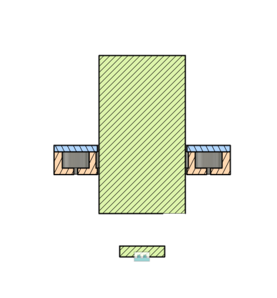
Here is what the CAD assembly of the 5 separate 3D printed pieces looks like:
Read on for more about the tweaks needed and next steps!
---------- more ----------
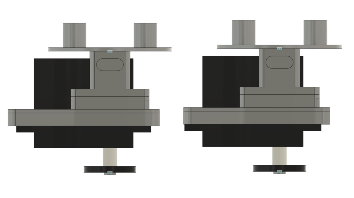
The installation process isn’t as tedious as thought it would be. You have to hold the servo by the cable in one hand, and position the magnet clamp onto the servo with your other hand holding the dowels. The tolerances of +0.4mm on each side of the servo were adequate for clearance and with no wobble.There will be some tweaks needed in the next revision. The corners of the servo bracket are touching the inner diameter of the enclosure (left). This affects the position of the servo horn to be offset (right).
The tweak on the next revision will be very small. Can you spot the difference?
The bump from incorrect fastener diameter and length will also be solved after an order for fasteners.
Now with this gate cleared, it’s a step closer to running this experiment soon to test some of the hypothesis. The next step is the internal and external servo horn in rigid. If it struggles, then the next step is internal servo horn in flexible.
-
Mech Update #02
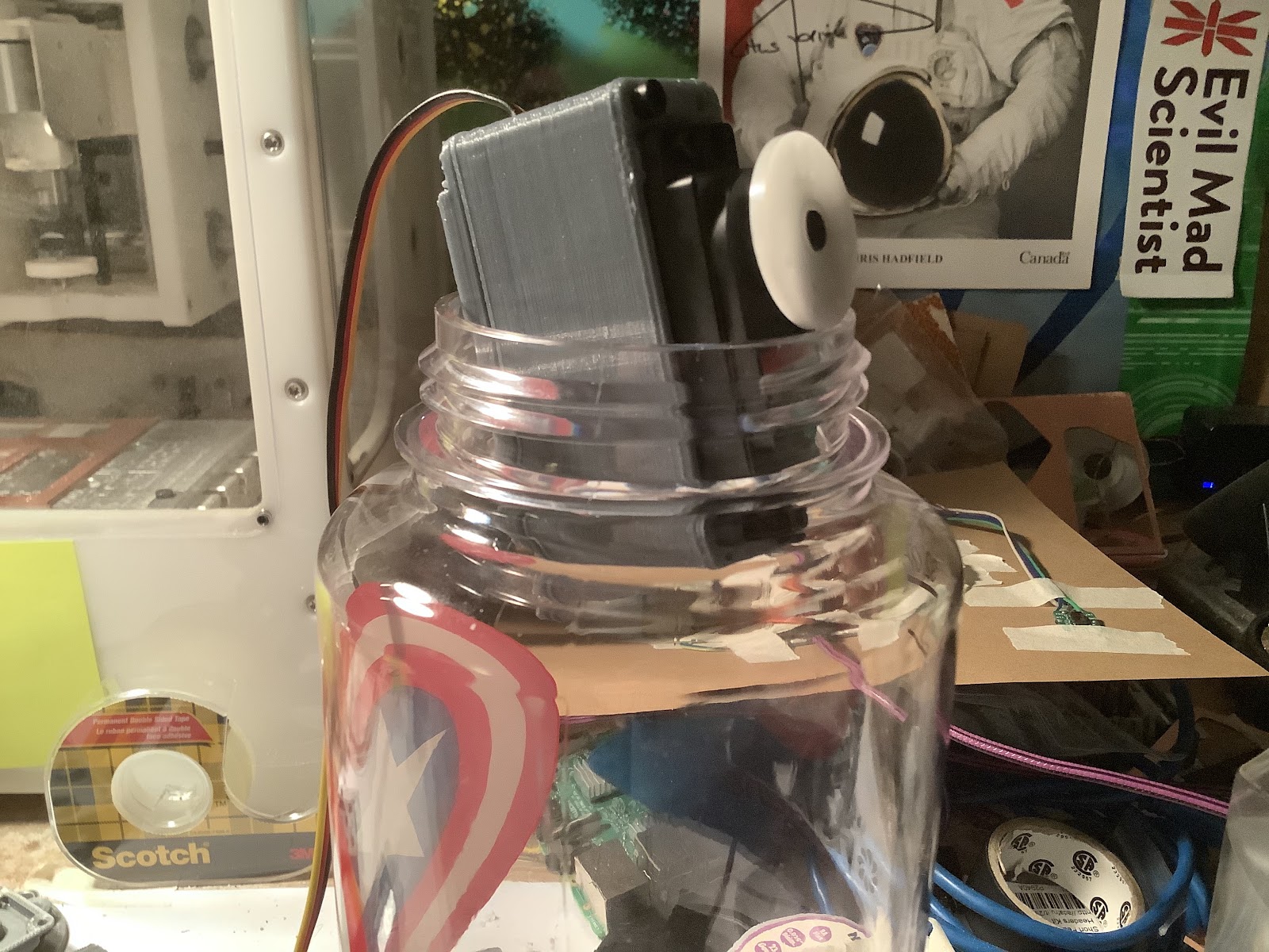
08/02/2020 at 06:24 • 0 commentsThis update is all about iterating the servo block assembly. The servo block will be inside of the intelligent buoy enclosure (Nalgene bottle). It needs to be attached with magnets to the rest of the stages because the dimensions are too small for a direct attachment.
Decreasing the size of the servo block assembly was iterated on 3 times since the last update.
Read more for CAD screenshots and photos of the 3D print!
---------- more ----------For R2, the width was decreased, and in general the construction of the magnet plates was better.
R2 did not work - too wide for the enclosure. Next try was R3. Removed the 4 magnets and only had 2 now. Thinner along the width by reducing all the extra space. Also made the magnets closer to the motor (which could have problems, but first trying to design).
Here’s how it looks printed and assembled:
Did it work? Nope!
For a sanity check, I disassembled it and made sure that a servo can still fit in the enclosure.
This spurred a thought - what if attach the magnets to the main bracket? Could that work? This is what R4 is about. R4 is a different approach. Two magnets on the side of the servo.
While writing this, the pieces for R4 are printing. If R4 doesn’t work, maybe making the magnets flush with the side of the servo could help reduce even more space.
Also, might be thinking about the design problem from an obscured angle. Maybe a very thin magnet (think ‘tape’ style) could be used for rudimentary alignment, then keying with 3D printed pieces could be used for stability.
Alright, the pieces for R4 finished printing and now assembled …….. the result: it fits!
2:30am here but it’s a relief to know this fits now. Next steps are to proceed with the servo horn design, then electronics for the test, then testing it.
-
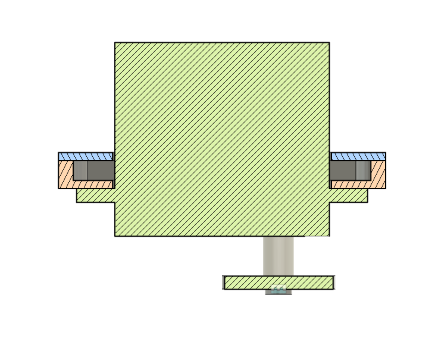
Information about Sleeve Bearings
08/01/2020 at 21:32 • 0 commentsIt's likely we'll be using a sleeve bearing made from HDPE in the rope spool box. It was interesting to see design of these is somewhat like an art. Check out this project log for my research notes!
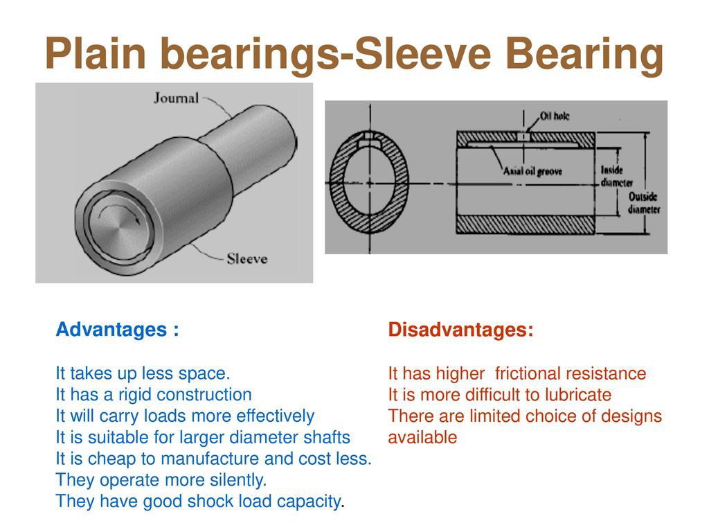
What are sleeve bearings? This presentation is useful review.
[source]
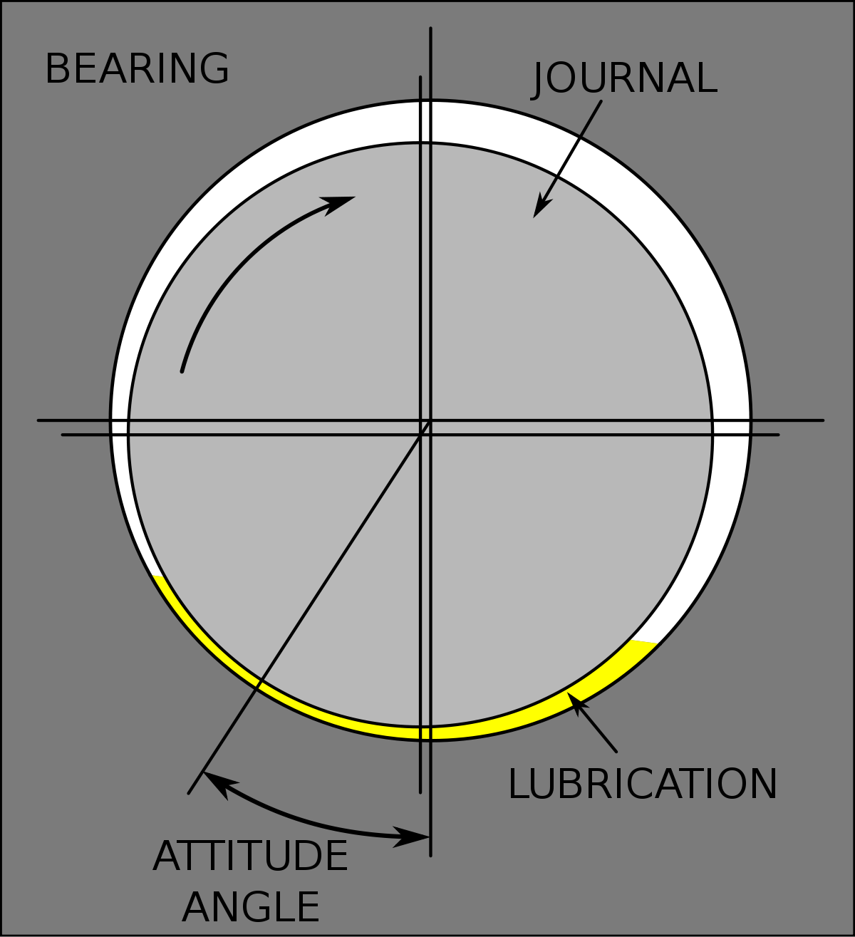
Read on for more of my notes!---------- more ----------What happens when a sleeve bearing is in action? The lubrication between the bearing and journal gets "squished". The attitude angle is where the loading on the bearing will be the most.
[source]
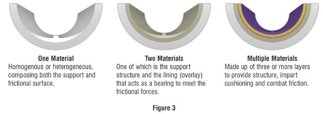
What is a sleeve bearing comprised of? It can be multiple materials, or just one. There will eventually be abrasive wear.
[source]
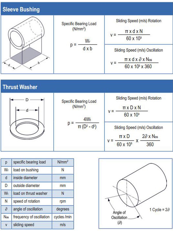
How do we calculate information for the design of sleeve bearings? Calculate the load factor PV, p for pressure, v for velocity. Inputs are the load on bushing in N, inside diameter in mm, and length in mm. More information available here.
[source]
How do we know how much clearance to place? Keep in mind the precision of the tools being used to cut it. Here's one rule of thumb mentioned in this article: 0.0015 in. per in. of diameter. However, as that article mentioned, there are a few different rules of thumb, so testing is necessary!
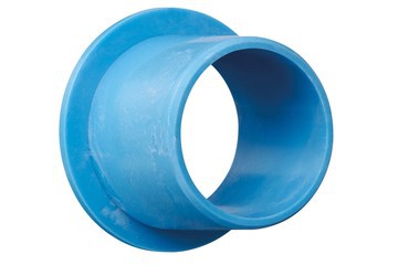
What are some examples of sleeve bearings? Check out the igus iglide bearings. There's a variety that is explorable on McMaster-Carr.
[source]
-
Mech Update #01
07/30/2020 at 05:59 • 0 commentsThis week, prototyping has started! Here's an update on what's been happening so far from the mechanical side.
![]()
Read more for prototyping for experiment #1, the spool box mockup, gifs of waves, and more learnings.
---------- more ----------Prototyping - Experiment #1
This week is experiment #1. The objective is to determine if a magnetically coupled piece will work through the enclosure. This means that the servo and electronics will remain watertight, and the outer piece will be in water. Stretch goal for experiment #1 is to try some super bright RGB LEDs, and observe the surrounding illumination in lake water.
We are going to be using a Nalgene water bottle for the prototype enclosure for the experiments, then ideally transition to a tube. The hope with a Nalgene is that it provides a somewhat accessible enclosure available off the shelf. The material, Tritan aka polycarbonate, can withstand a decent amount of pressure needed for testing. The lid however may prove to be weaker. (Might be able to 3D print the lid in stronger material though!)
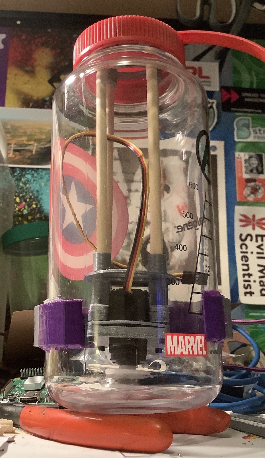
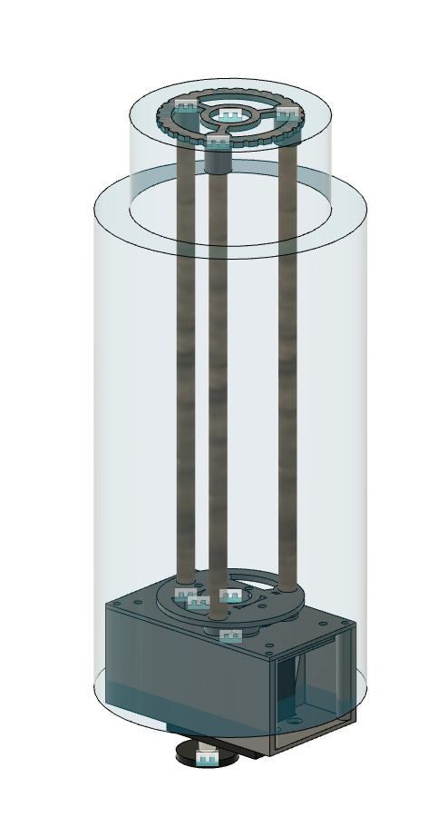
Here's the premise of the setup. There is a 3D printed piece that attaches in to the lid. Wooden dowels extend from this to provide structure that various stages could be added on to. Those stages will hold on to the battery, controllers, sensors, and the servo.
This model with the servo block extending beyond the enclosure clearly illustrates one of the major unknowns at the moment - which is how much space the servo block will take up. Once this is known, then the lengths of the wooden dowel can be adjusted properly.
Here are some embarrassing mistakes made so far ....... and don't worry, there's even more to follow ....... (Top left) Using a screw in the middle to clamp the lid to keep the magnets in - doesn't work, needs to be clamped from the other side of the circle. (Bottom left) Using krazy glue for the magnets and it not working, then needing hot glue - magnets no longer flush. (Right) Slicing and printing a part upside down.
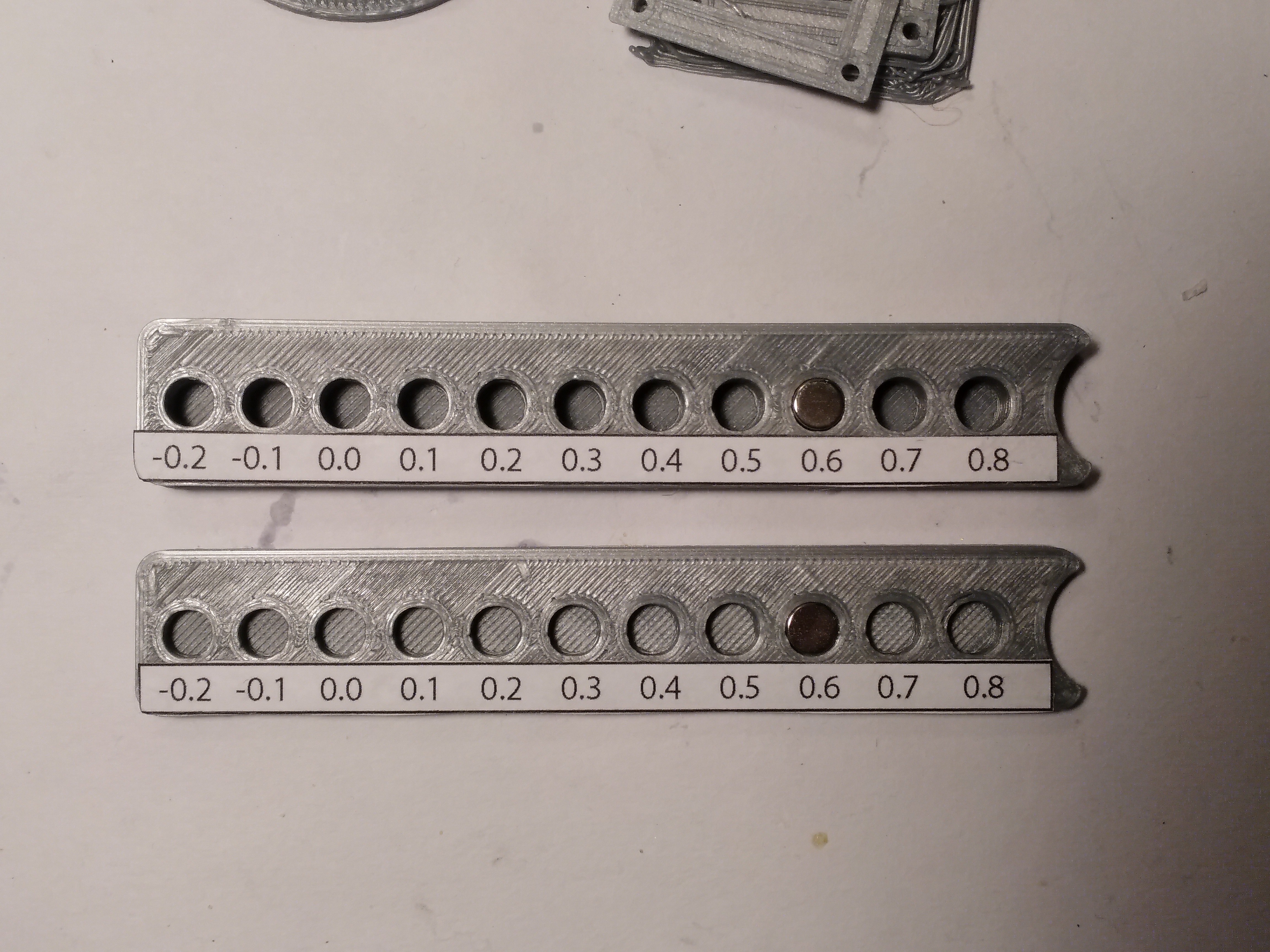
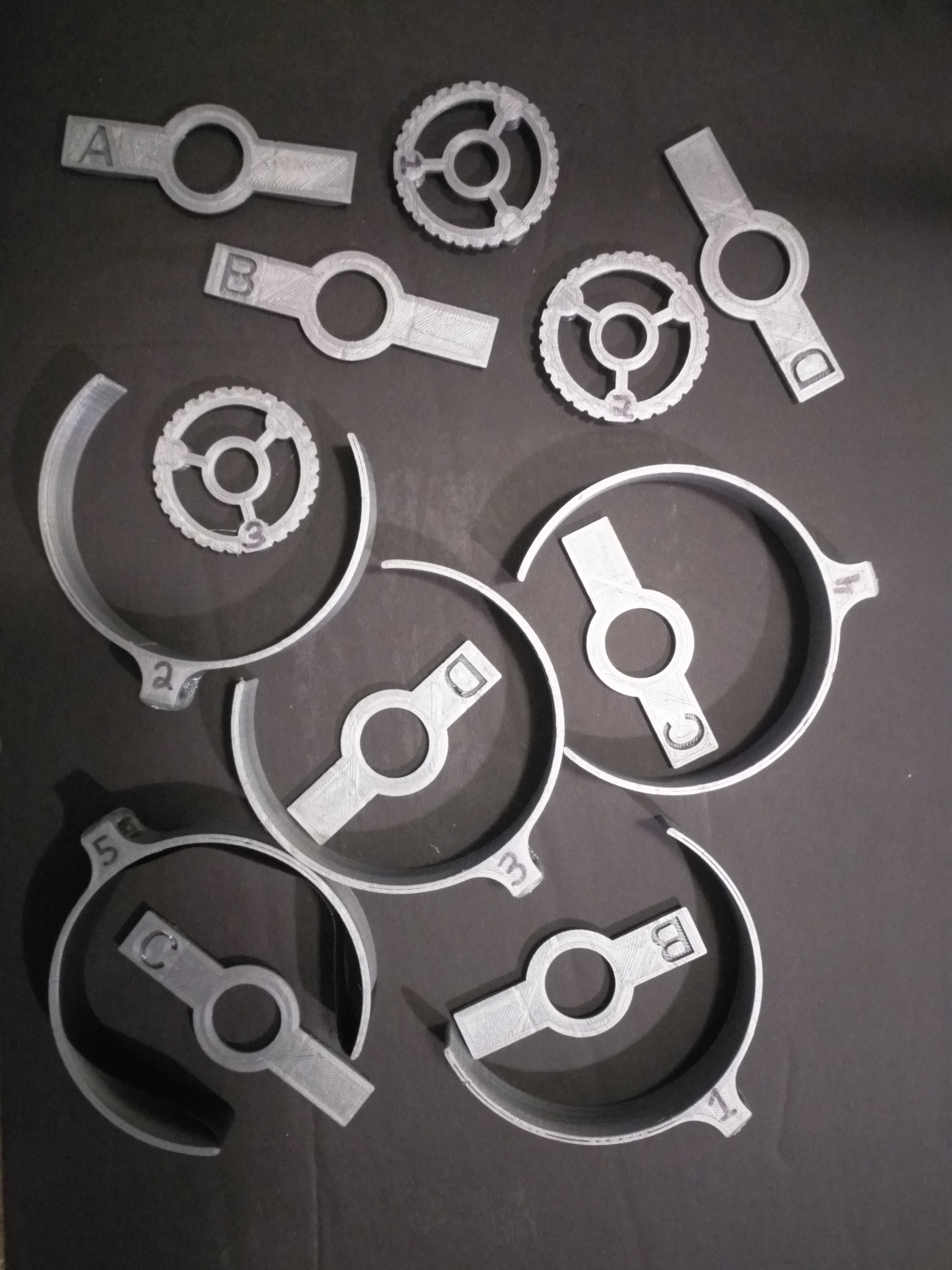
A better technique for the magnets would be to pause and insert them mid print, then resume. The reason why I went with the screws method was because I wanted to make the prototype quickly, and having everything printing off without closely monitoring it was faster. This can be done for future prototypes if the experiment works. Additionally, can change the magnet sizing parameter in the design, and maybe it can hold with friction. Here are the magnet sizing tests.
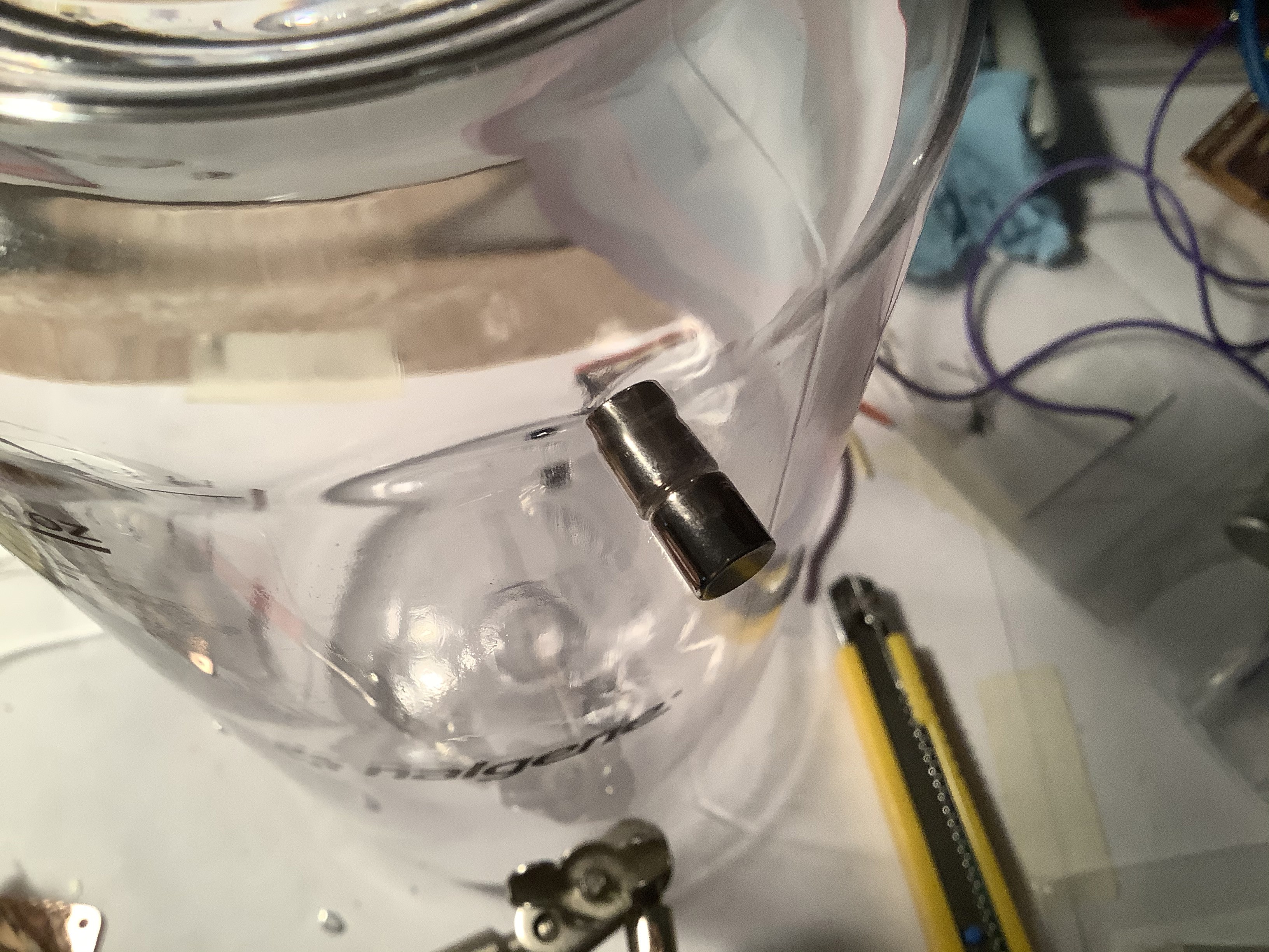
Here is a simple magnet test on the outside and inside of the enclosure.
![]()
There will be at least 2 external pieces that clamp on to the enclosure. The external clamps will have a handle, and this is where the rope from the spool will be attached. Also may consider attaching a GoPro to this, for verification of testing experiment #1.
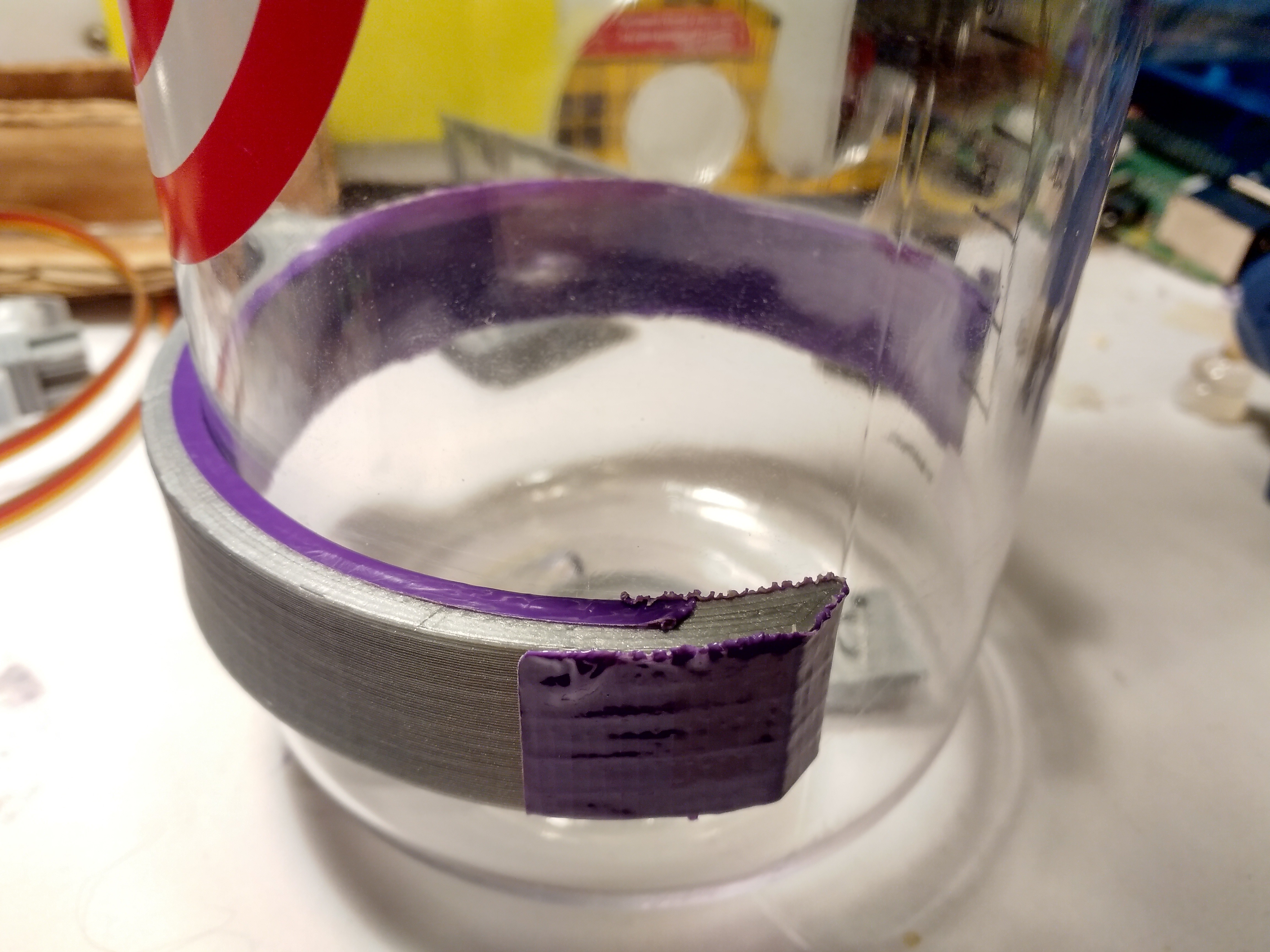
Prototyping the external clamps involved many iterations and adjustments. The PLA and polycarbonate interface had low friction. Electrical tape somewhat worked but un-adhered. The purple duck tape looks promising until cutting some rubber gaskets for it.
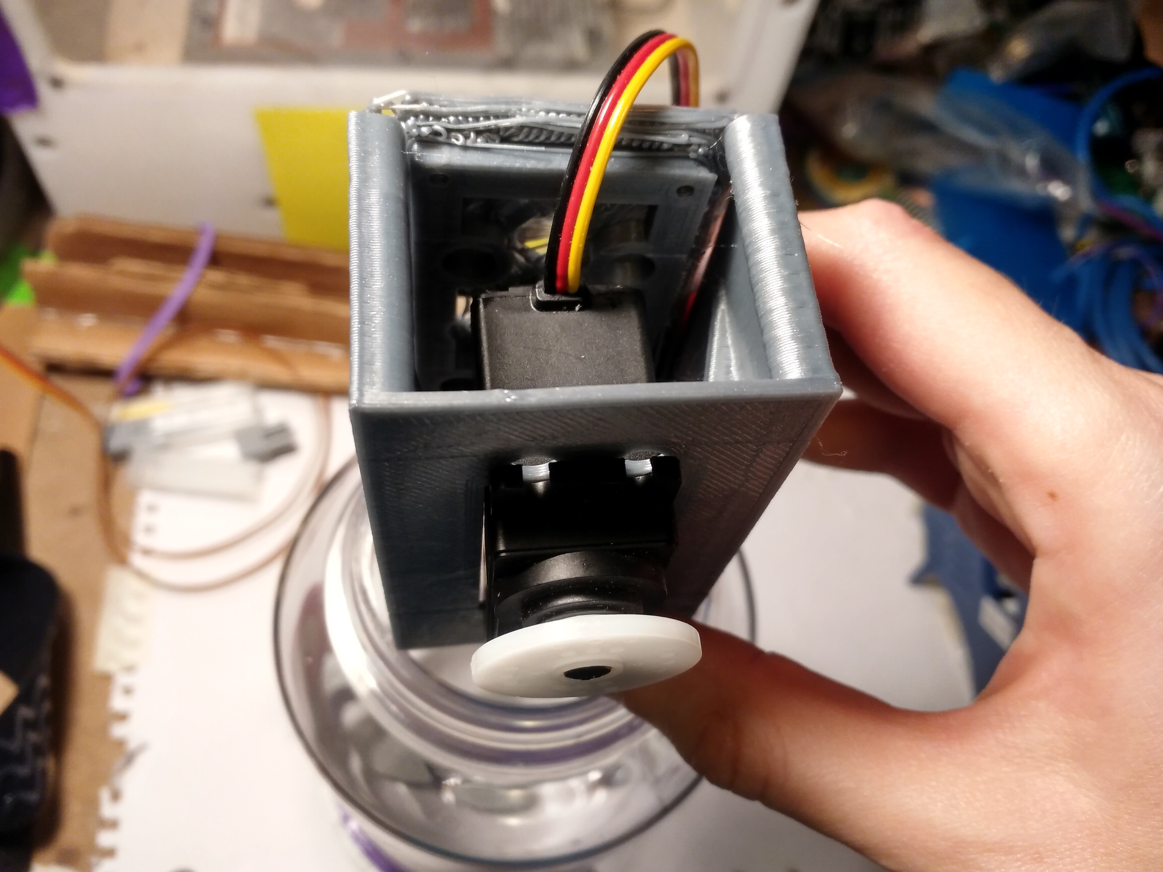
Ready for the next embarrassing mistake? The servo block does not fit. It needs a redesign and another few iterations. Considering changing from 3 dowels to 4.
![]()
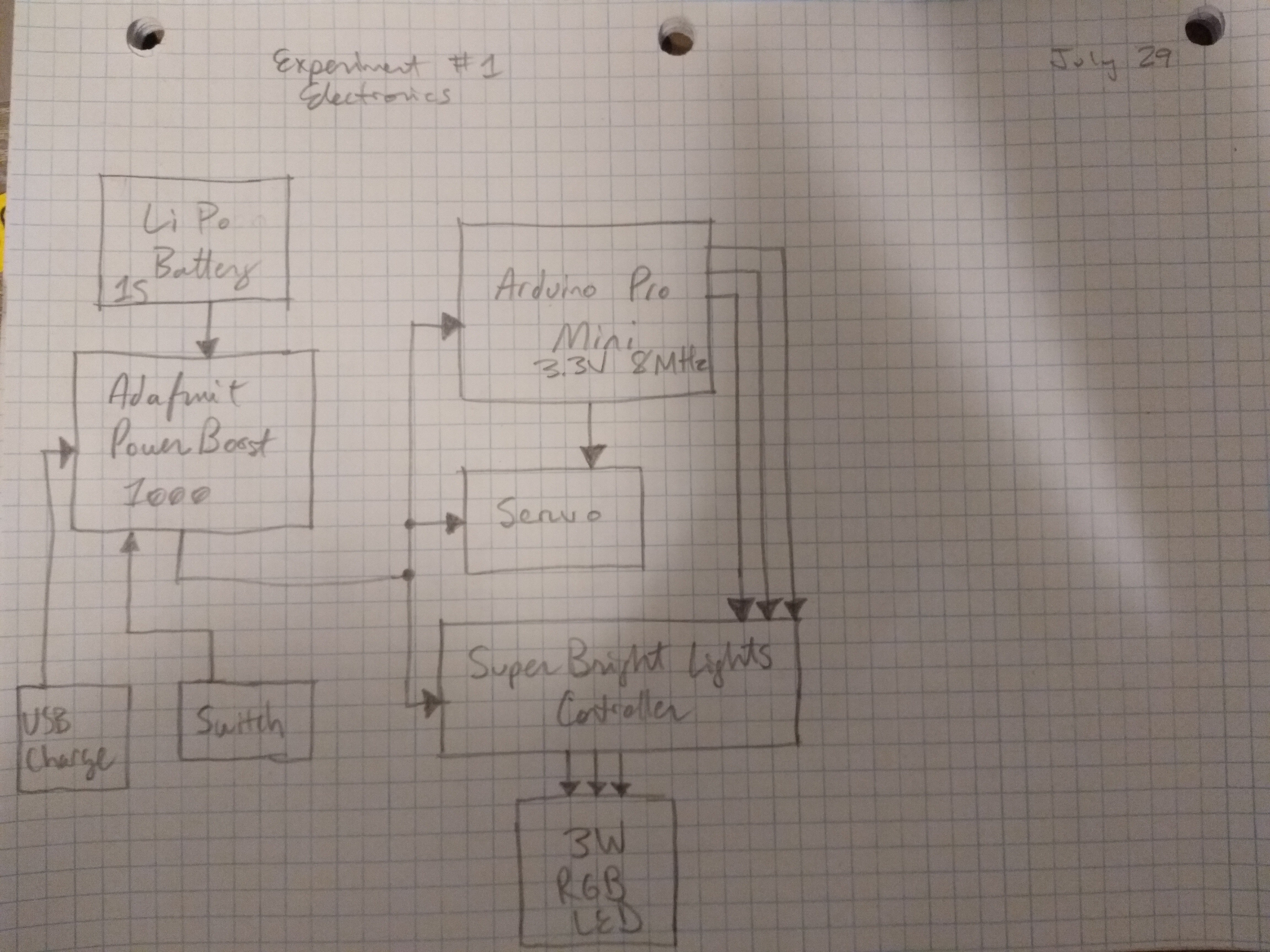
Here's what the electronics will be for experiment #1. (This is what have on-hand, and different from what Leo and Tobi are working on)
![]()
More progress to follow.
Spool Box Modelling
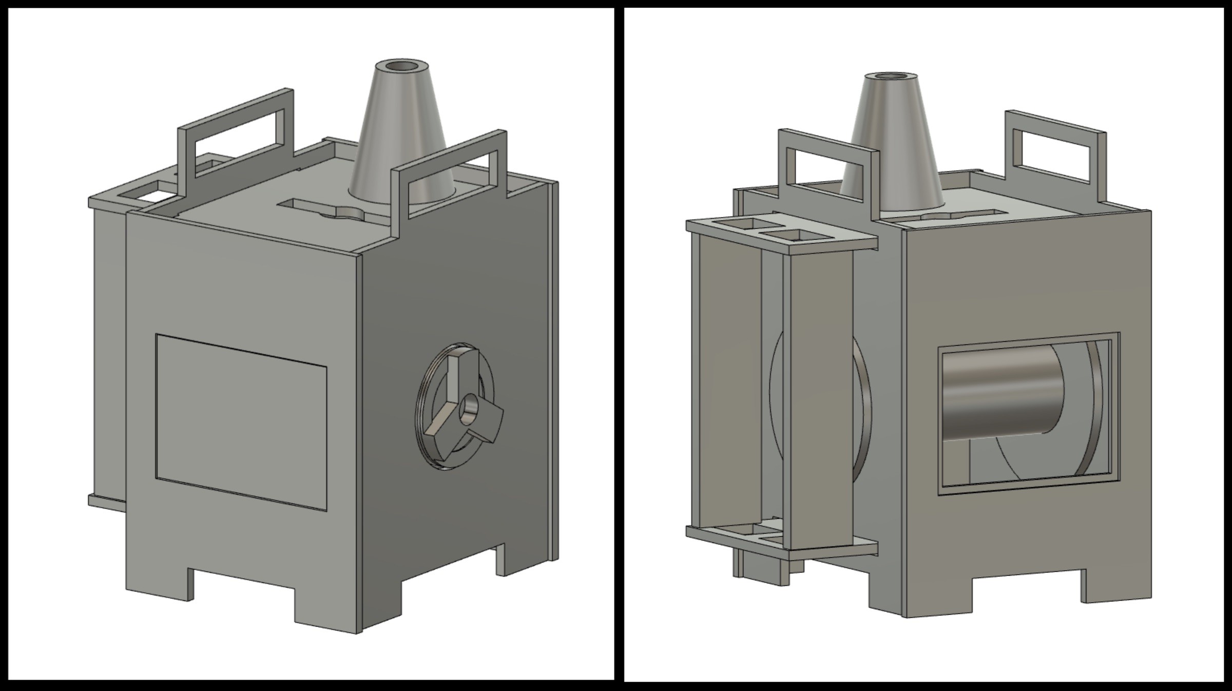
The spool box is what will house the rope, and the intelligent buoy will be resting on it until timed release. The sides of the spool box have areas for rope to be tied to, which attaches to the gear. There are handles at the top for the fisher to retrieve it. It will use HDPE, which resists biofouling. HDPE is buoyant, so the assembly might need some steel plates on the bottom for ballast. The tapered cone at the top is to guide the rope when unspooling. The box design was inspired by the Othermill / Bantam Tools mill.
![]()
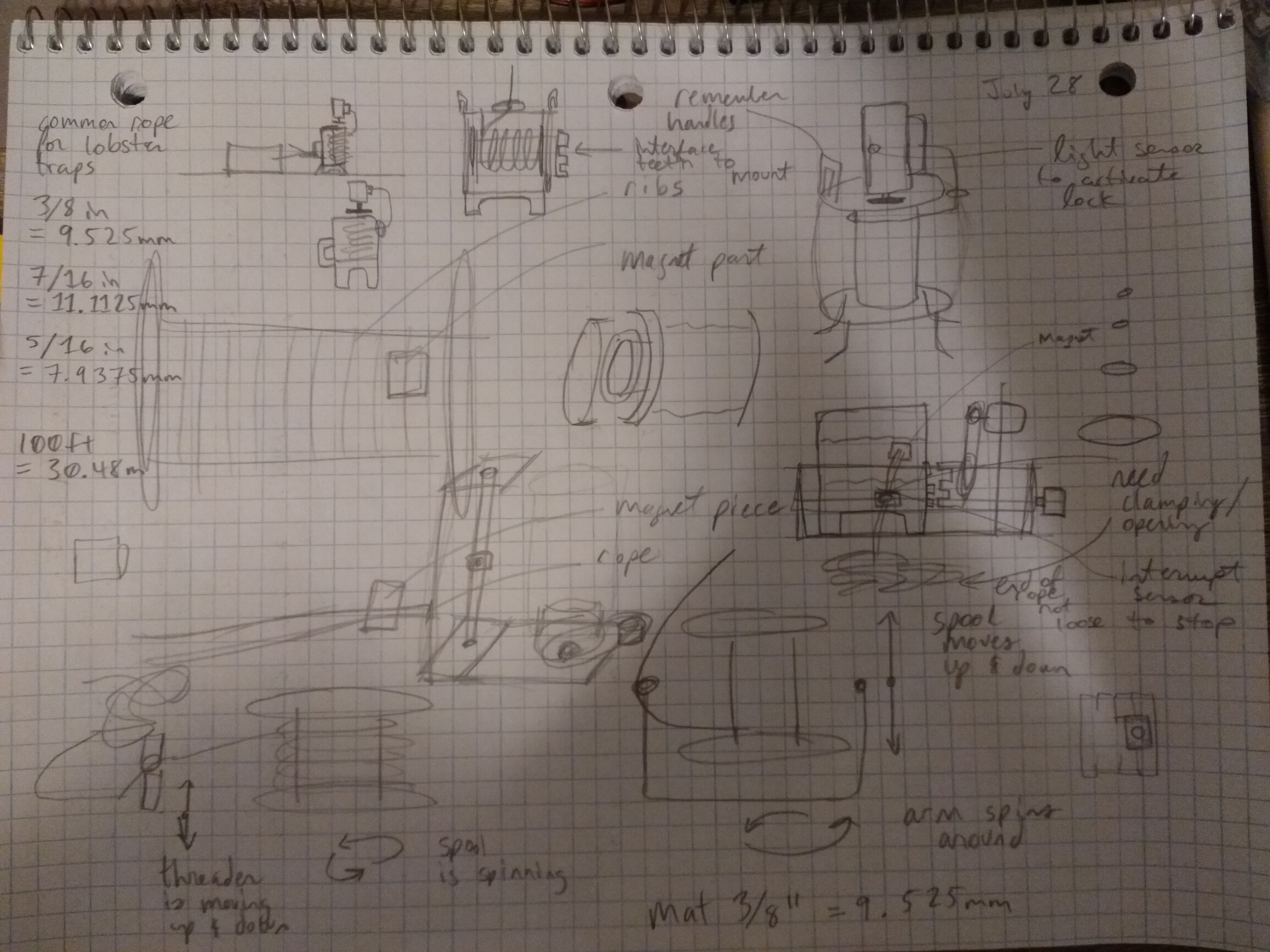
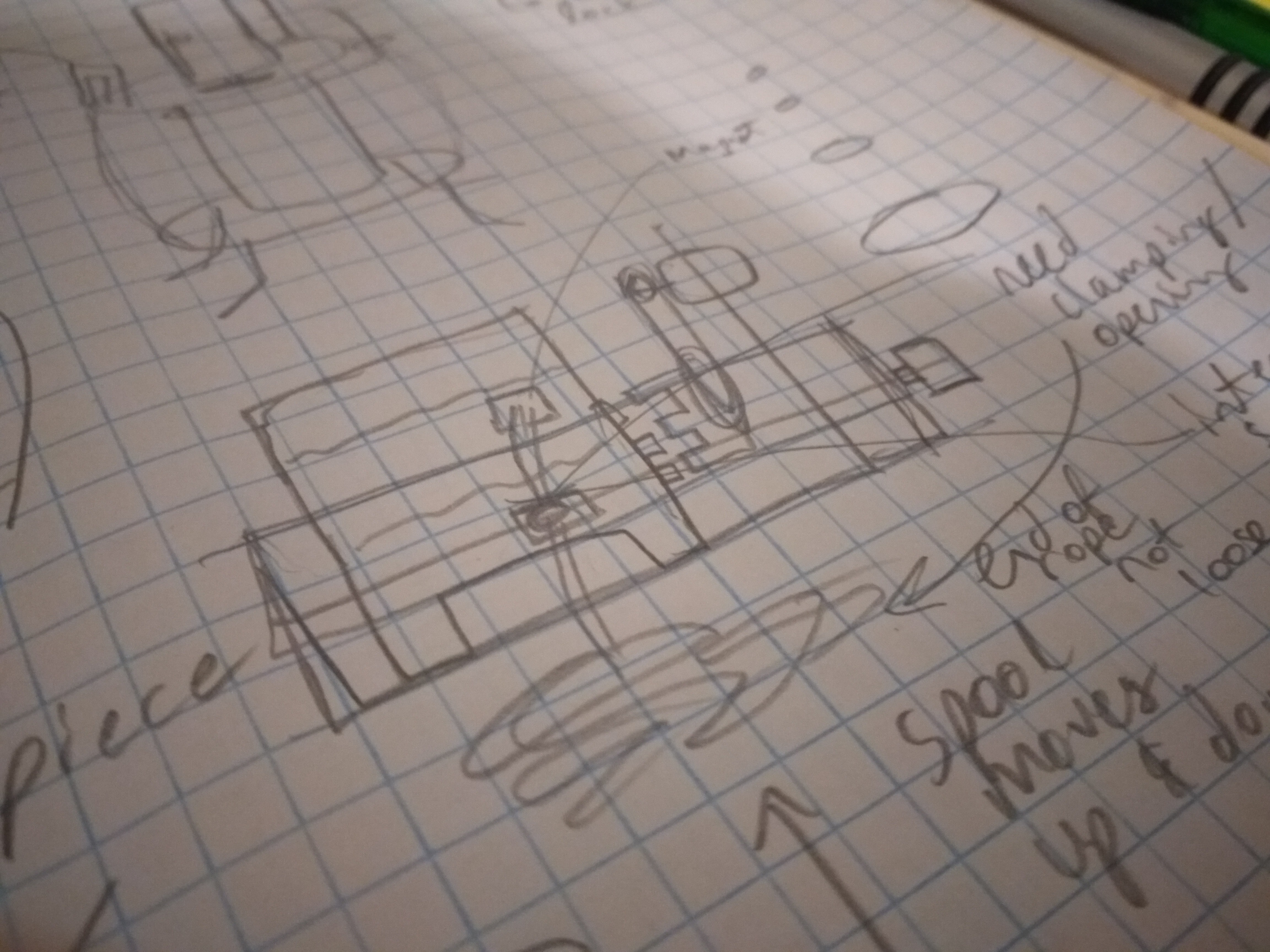
The spool box will be able to sit on a device that will help automatically re-spool it. There's a key interface on the right hand side. Not wanting to introduce bearings to water, especially salt water, I wanted to see if two concentric rings of HDPE would be able to work. Later learned that these are called sleeve bearings, and it seems like HDPE is a good material for it. For automatic re-spooling, I was researching how fishing lines are re-spooled, as well as sewing machine bobbins for inspiration for this. This is what brainstorming looks like for me along the learning journey:
![]()
Here's the concept of the automatic spooler. What, you don't understand it? (jokingly)
Update on EVERYTHING Else
Random: There are a variety of things that come up that need some research and exploration to understand it better. This week so far, I've also learned about:
- Sleeve bearings
- The material HDPE
- Seals
- Pressure under water
- Evaluating curvature of nalgene bottle without cutting it
- Some rules for deploying ropeless systems for testing in the ocean in Canada
I still have more to learn about seals, and have heard that there's a handbook for o-rings sizes.
Teamwork: Team wise, I made a mistake about when organizing a Doodle for a meeting of not including all of the hours (the ones I wasn't available in). Everyone is bound to miss a meeting at some point. Adding all the hours would have saved some confusion. Will do better next time!
Meetings: Much of the contacts initiated in week 3 am finally having discussions with. It's been inspiring to hear how much people working in the same area want to help each other out with knowledge.
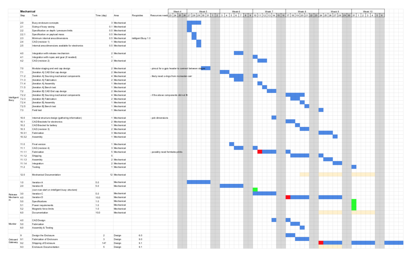
Gantt chart: Week 4 was figuring out timelines and making a Gantt chart. Leo and Tobi and I added each of our area's tasks to the list. Below shows the tasks and timeline of mechanical. Right now I'm in the process of experiment #1. The red boxes mean deadlines for sending files for fabrication — aiming to push earlier on these if all goes well.
Parts list: Parts list getting there, and will likely order some materials and fabrication items tomorrow (today). Might need to delay a McMaster-Carr order for the o-rings til Monday, however this will give me some dedicated time to dive in to the o-ring sizing.
Test spots: What do you think about these two local spots and conditions for possible early testing? 😉
![]()
![]()
Ok, maybe calmer waters to start with first.
Next step: The next step is to iterate on the prototyping above and run experiment #1. Future updates will be shorter but more frequent. Shifting to logging what has been done every day for 15 minutes, and posting every couple of days.
-
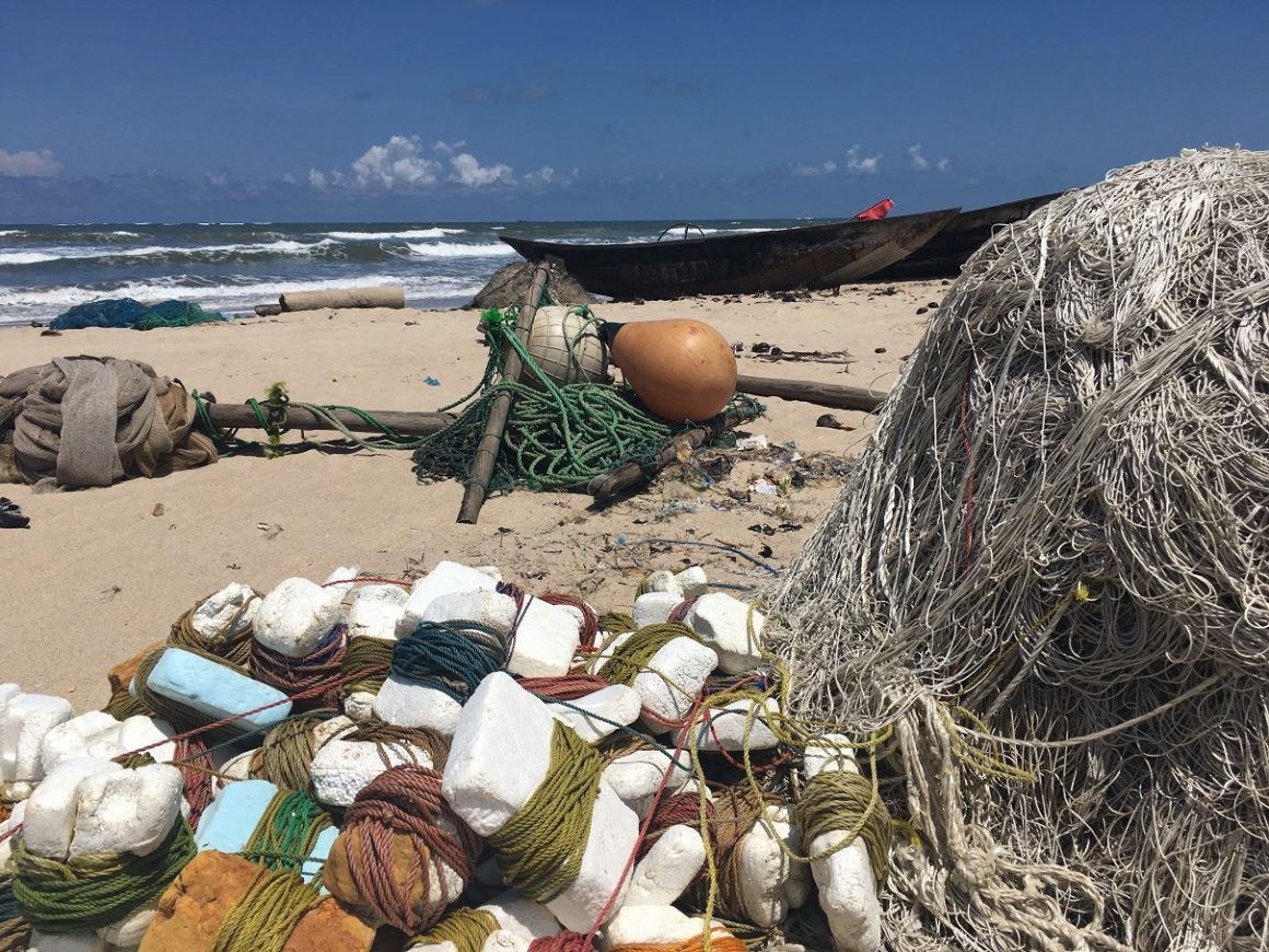
Eja in the heart of the fishers
07/27/2020 at 13:02 • 0 commentsWhen we started the project, it important we gather as many data as possible one of the thing I tried to do locally is to understand the challenges they are facing around the ghost gears issues and we can solve it for the.
We realized that the problem is different from each country like in Nigeria, some fishermen have been fishing for over 100 years and its difficult for them to just change the way they are used to about fishing.
![]()
But it gave us a great insight into different problems they are facing, chatting with a fisherman he said "When you cast your net, you cast it with lot of aspiration that you might eventually get a catch. While doing that, what is the effect on the environment? Yes GARBAGE and lost of the fishing gears"
It shows they are also concern about the garbage and they are opened to solve it, based on my research, three communities in Nigeria are faced with the general and most common problem which is GHOST GEARS. Some fishermen that have little knowledge of environmental challenges burn theirs, but others didn't even care about it.
2021 HDP Dream Team: EJA
Learn more about Team EJA's intelligent buoy, and how their solution will help the global fight against ghost gear.


 Read on for more about the tweaks needed and next steps!
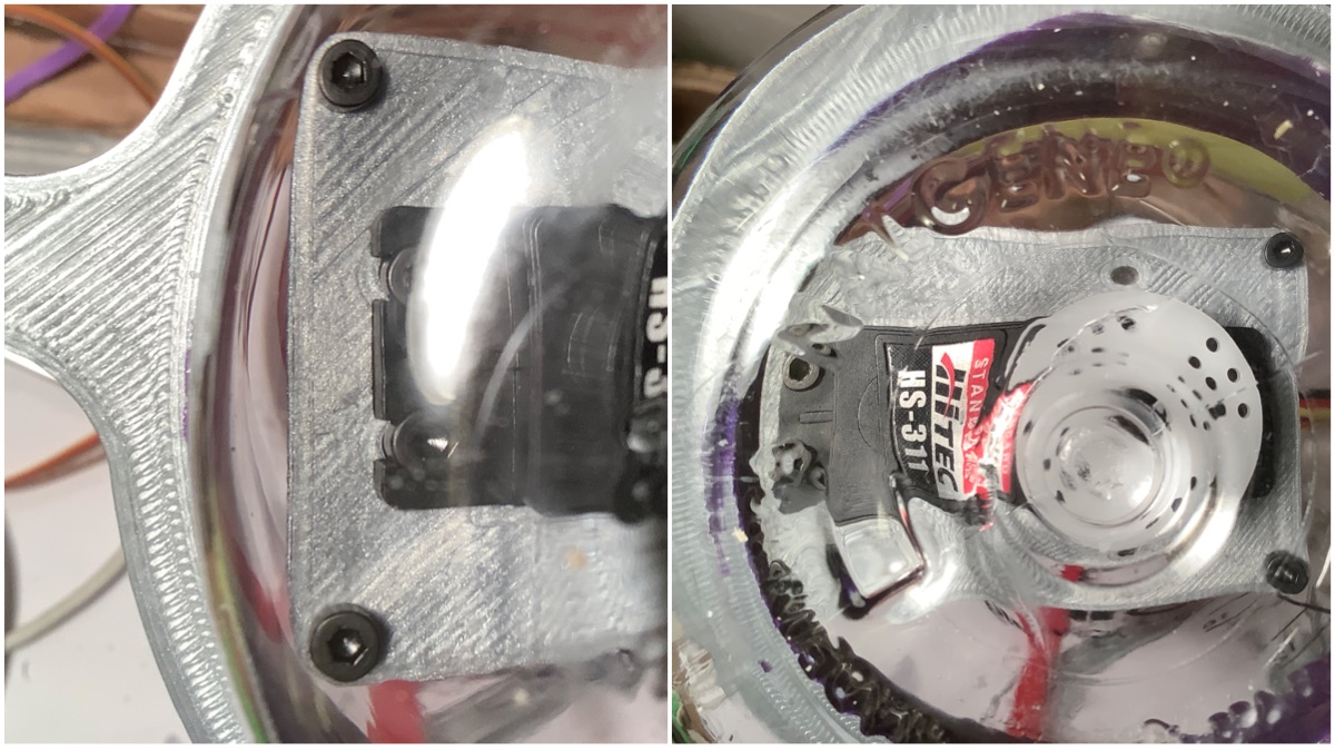
 This update is all about iterating the servo block assembly. The servo block will be inside of the intelligent buoy enclosure (Nalgene bottle). It needs to be attached with magnets to the rest of the stages because the dimensions are too small for a direct attachment.
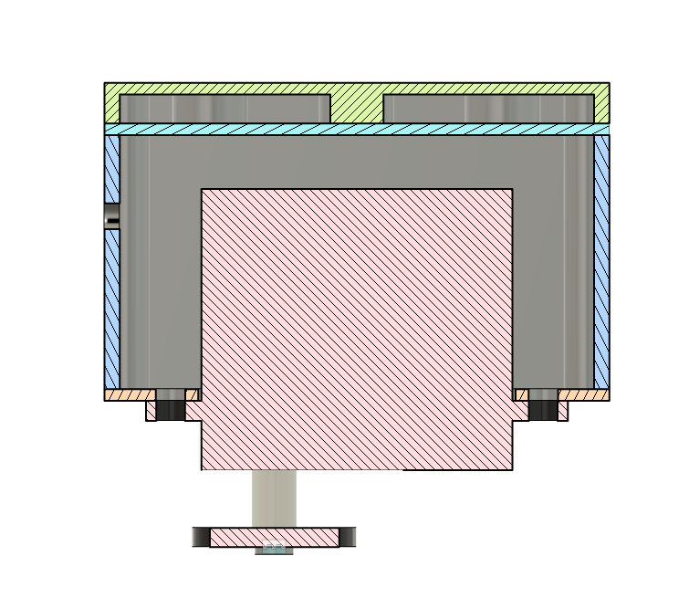
 [
[ [
[ [
[ [
[ [
[
 This model with the servo block extending beyond the enclosure clearly illustrates one of the major unknowns at the moment - which is how much space the servo block will take up. Once this is known, then the lengths of the wooden dowel can be adjusted properly.
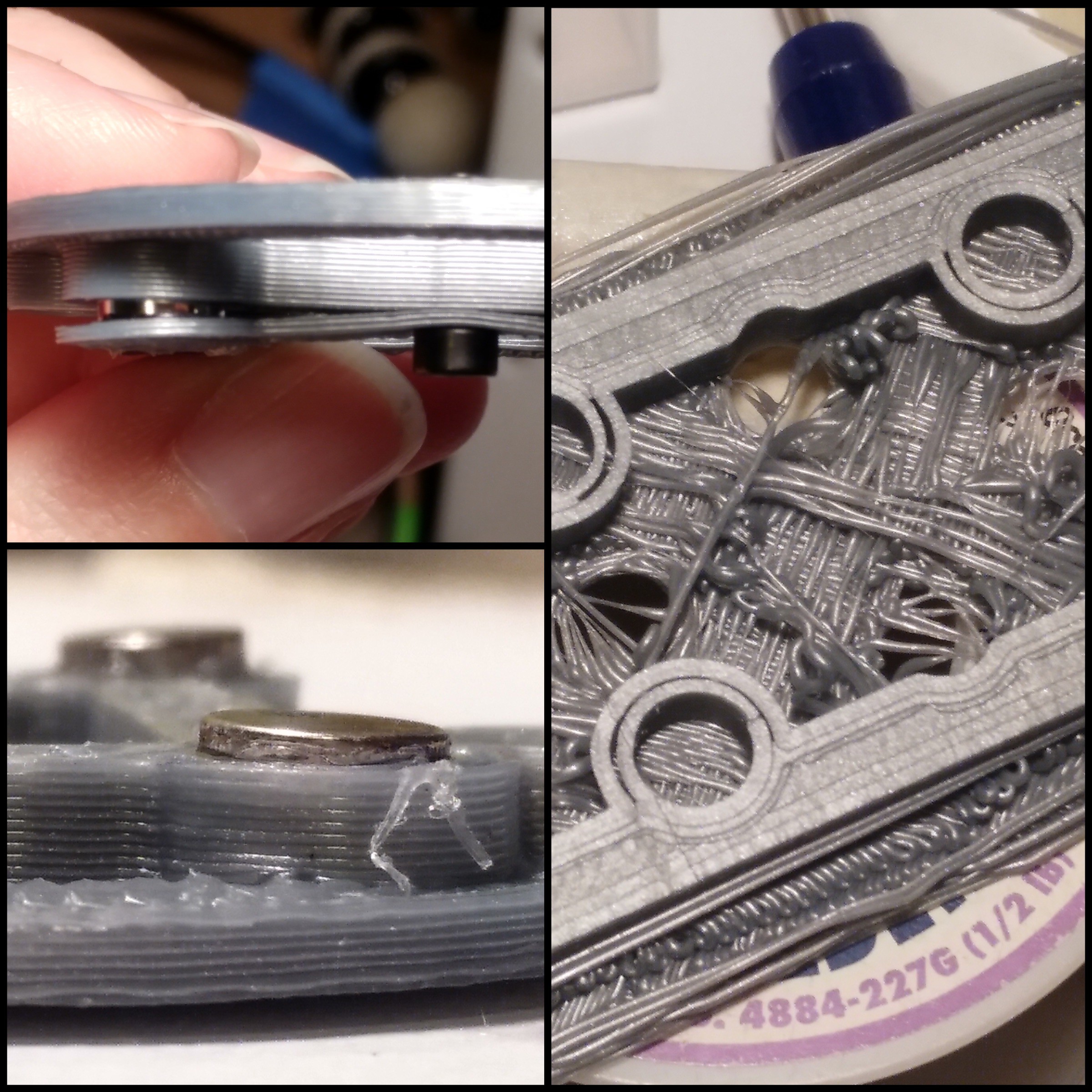

