-
1Selection of a bluetooth module
Fist I planned to use a HC-10 clone, the AT10 with bluetooth 4.0 LE for low energy consumption. Unfortunally Bluetooth 4 LE is not suppported by the Bluetooth to GPS app. Furthermore I learned that Android can not connect to 4.0 devices via the usual dialog in the system settings! If understand it correctly one can only connect to low energy devices via a program that is specially made for the 4.0 protocol (like the Bluetooth-Serial-Apps in the Google Play Store).
I then selected the readily available and cheap HC-06 module, with bluetooth 2.0 and slave only. It uses more power then the BLE module but at least it works.
It was easy to import the part and footprint into KiCAD, since it was all available on easyeda.com. A minimalistic 5 pins are used in my design: Vcc, GND (2x), TX and RX. Additionally a 1 µF capacitor was added to smooth the power surge while paring. -
2PCB design and manufacture v1.0
To make it clear from the beginning I am no electronic engeneer so the PCB design is made as best as I could following the hardware integration advice from the u-blox module documentation and common electronics knowledge. The same applies to the via placement. I have a basic understanding of their function when it comes to connecting the ground planes to avoid noise in signal lines but would not garantee that the placement is the best. The PCB was made at home (see my other projects for a detailed how to). Since I had the troubleshoot a short circuit in my first design, the PCB looks like a 5 year old tried soldering for the first time :)
To the description of the circuit: I tries to use 0805 parts only because I like that the parts are quite small but sill good to solder by hand. One 18650 battery (protected) is the power source for the module. The u-blox module as well as the HC06 and the TX/RX signal lines work with 3.3V. A LP3981 LDO (200 mA) voltage regulator with a couple of capacitors generates the 3.3V for the circuit. Here comes the first dirty fix. Id had to use a MCP1703 in TO92 instead of the SOT23 part because I ordered the 5V and not the 3.3V version :/ The datasheet of the M8N module suggests to insert ferrite beats or resistors > 10 Ohm in the TX/RX signal lines, if the traces are longer then 10 mm since they could act as antennas. I choose the 1k ferrite beats which were suggested. In the first design the TX/RX signal lines are also broken out to solder pads for development, the final version will not have these.
A battery (battery clip for a CR1216, CR1220 or CR1226 battery) supplys the 3V backup power for the GNSS module (real time clock etc.). With this the satelite fix is significally faster than a cold start (see datasheet, 1 sec. with a battery compared to a cold start 26 sec. for GPS/Glonass). The part where I was very uncertain was the antenna circuit and via placement in this region of the PCB. I followed the suggested circiut from the u-blox hardware integration manual for active antennas. My patch antenna (Molex 206640) has a build in LNA so it needs to be powered from V_ANT. Part placement was done so that the signal lines were quite close to the RF_IN pin of the GNSS module. Vias were placed around all parts to garantee a good grounding and hopefully little noice pickup.
-
3u-center software
The software makes it possible not only to get position information on the computer but also to configure the module and all its functions. The default way to configure a M8-module is per serial 9600 baut 8N1. Once connected the software displays all available satelites, used satelites, position on a map, coordinates, velocity etc. The best way for me to get around with it was to play around with it, but of course there is a very detailed manual for it (It is quite lenghly though).
Installation on Windows
Installing on Windows is as easy as clicking the installer and you are done.
Installation on Linux
It is also possible to run it under Linux (Ubuntu in my case). First install wine via sudo apt install wine. Then run the u-center_install.exe and follow the dialogs. Once installed check wheather there is a soft-link to your current USBtoSerial device (usually ttyUSB0) in the folder ~/.wine/dosdevices.
If there is no comX link to your device simply create one like so: ln -s /dev/ttyUSB0 ~/.wine/dosdevices/com3
To start the u-center.exe start it via wine: sudo wine start /unix ~/.wine/drive_c/Program\ Files\ \(x86\)/u-blox/u-center_v20.01/u-center.exe
Assuming you installed it in a windows like fashion under c:\Programm Files (x86)\u-blox\. To avoid the sudo command add your user to the dailout group.
I have tested the software for a while and had no problems with it under Linux.Disclaimer: I got the tips for installing under Linux from https://wiki.paparazziuav.org/wiki/Sensors/GPS#Installation_on_Linux
-
4NEO8M configuration with u-center
To configure the u-blox NEO8N module you can hook it up via serial or USB. Here I connected it with the USB port and the device registred as COM5 on my PC. In Linux you may have to check the com port since wine generates all com ports new on startup. Therefore one has to switch the device on before starting u-center in wine.
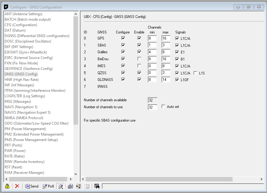
In u-center you have a enormous amount of configuration options plots. Under 'View' select 'Configuration View' to configure the device. To configure the GNSS satelites, click on 'GNSS (GNSS Config)'. There you can choose which satelites the module should use, make sure not to use more channels than available (32 for the NEO8N). To send the settings to the device, click 'Send' in the lower left corner. 'Pull' gets the current settings from the device.
Here a short explaination of the GNSS options:
GPS: North American Navigation System (32 working satelites)
Glonass: Russian Navigation System (24 working satelites)
Baidou: Chinease Navigation System (35 working satelites)
Galileo: European Navigation System (22/26 working satelites)SBAS: Satellite Based Augmentation System (GNSS augmentation)
"Augmentation of a global navigation satellite system (GNSS) is a method of improving the navigation system's attributes, such as accuracy, reliability, and availability, through the integration of external information into the calculation process. There are many such systems in place and they are generally named or described based on how the GNSS sensor receives the external information. Some systems transmit additional information about sources of error (such as clock drift, ephemeris, or ionospheric delay), others provide direct measurements of how much the signal was off in the past, while a third group provides additional vehicle information to be integrated in the calculation process. [...]" (Source Wikipedia)
IMES: An indoor messaging system
"An indoor messaging system (IMES) has been developed to meet the challenges of indoor and deep indoor positioning, as a system that can be implemented in any device that has a GPS/GNSS receiver without hardware modification. IMES can provide reliable 3D position data with a single transmitter device without performing range calculation. [...] "(Source https://www.gpsworld.com)
QZSS: Quasi-Zenith Satellite System
"The Quasi-Zenith Satellite System (QZSS), also known as Michibiki (みちびき), is a four-satellite regional time transfer system and a satellite-based augmentation system development by the Japanese government to enhance the United States-operated Global Positioning System (GPS) in the Asia-Oceania regions, with a focus on Japan.[1] The goal of QZSS is to provide highly precise and stable positioning services in the Asia-Oceania region, compatible with GPS.[2] Four-satellite QZSS services were available on a trial basis as of January 12, 2018,[3] and officially started on November 1, 2018.[4] A satellite navigation system independent of GPS is planned for 2023 with 7 satellites.[...]" (Source Wikipedia)
SLAS: Sub-meter Level Augmentation Service
"To reduce errors in satellite positioning, information that can be utilized to decrease these errors (sub-meter level augmentation information)—such as ionospheric delay, orbit errors and clock errors—is transmitted by Quasi-Zenith Satellites (QZS). Major satellite positioning errors include 1) errors caused by the small number of satellites and 2) ionospheric delay errors. Errors caused by the small number of satellites cannot be improved through sub-meter level augmentation information. Therefore, the ionospheric delay is the principal type of information that contributes to error reduction.[...]" (Source: https://qzss.go.jp)
![]()
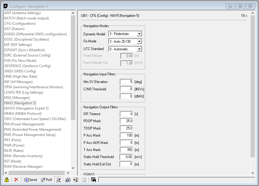
In the menu "NAV5" I set the 'Dynamic Model' to pedestrian for my hiking and mapping by foot. If you want to use the module in a car you probably want to change it to 'automotive'. The pedestrian model also works for speeds up to 100 km/h, but above it will loose the signal.
![]()
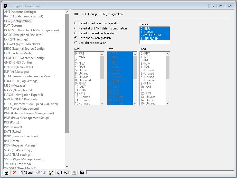
To save the current settings permanently on the device select 'CFG' in the list on the left hand side. There you want to select all four storage options and press 'Send' in the lower left corner.![]()
GNSS bluetooth module with u-blox NEO8N
Here I build a external GNSS module for mobile devices without or unsatisfactory navigation GNSS option.
Discussions
Become a Hackaday.io Member
Create an account to leave a comment. Already have an account? Log In.