-
13D Printing:
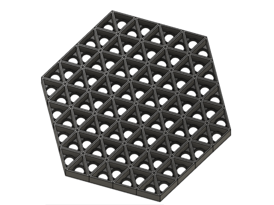
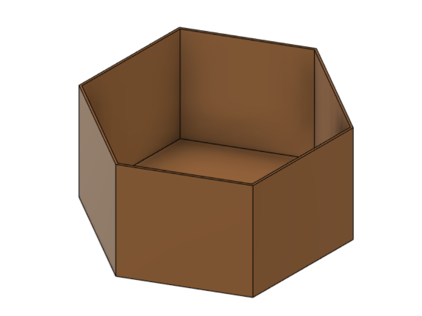
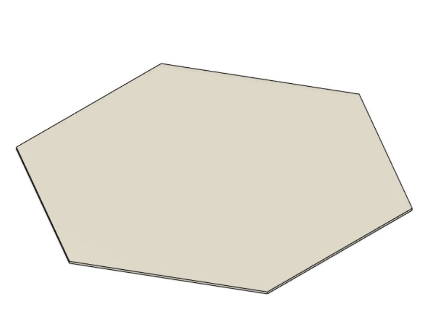
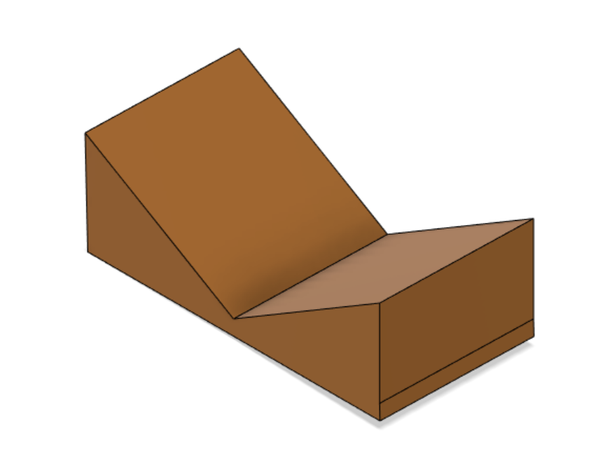
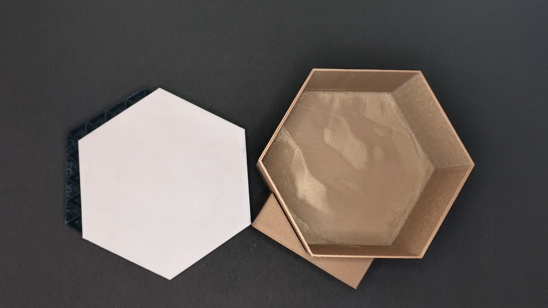
- 3D print all given 3D models.
- Print the screen layer in white PLA.
![]()
![]()
![]()
![]()
![]()
-
2Circuit Connections:
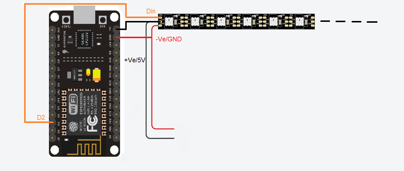
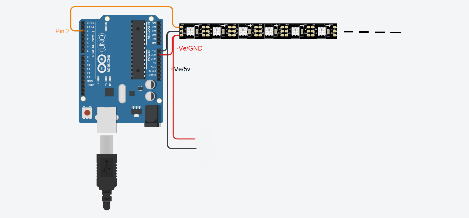
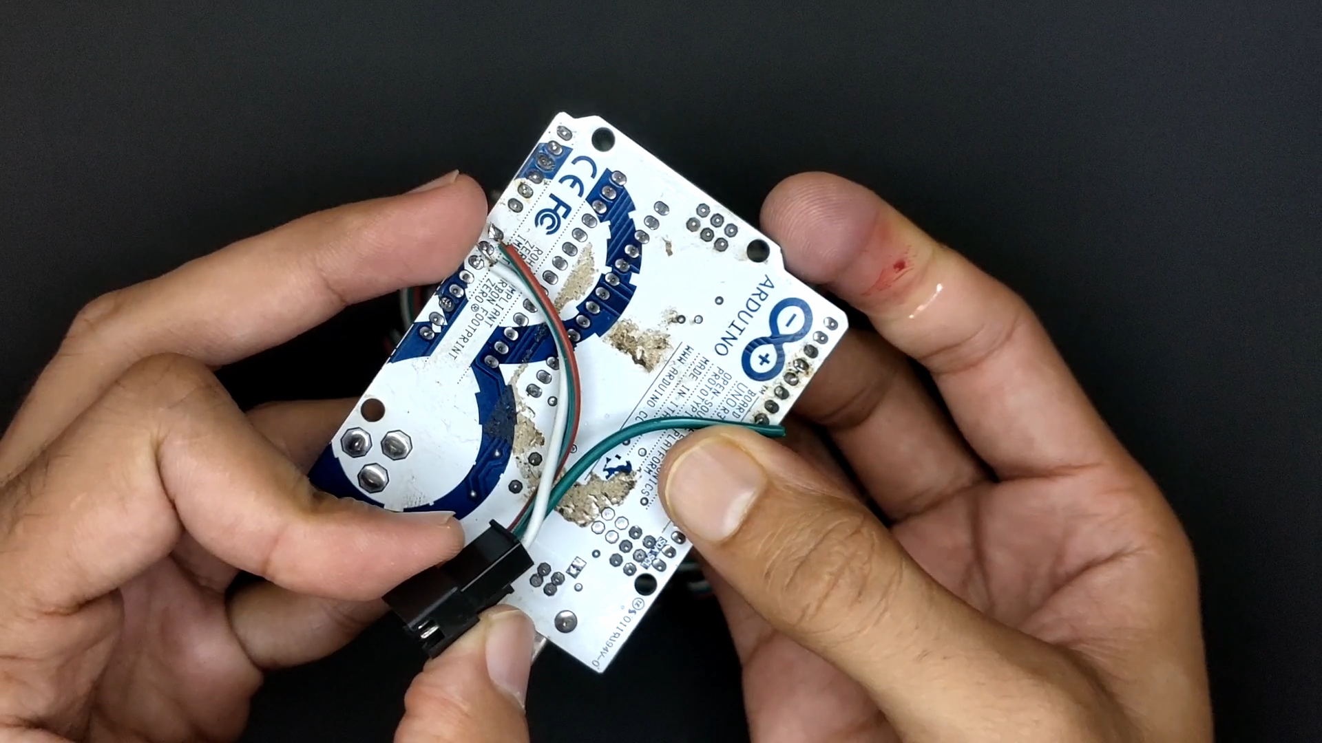
- Make all the connections as shown in circuit diagram.
- GND~-Ve
- Vin~5V~+Ve
- DataIn ~ Pin 2
- Also extend the power supply wires to last LED and connect, to prevent the voltage drop across the LEDs.
![]()
![]()
-
3Note:
- If you use Arduino board then you can only display animations,you cannot display time.
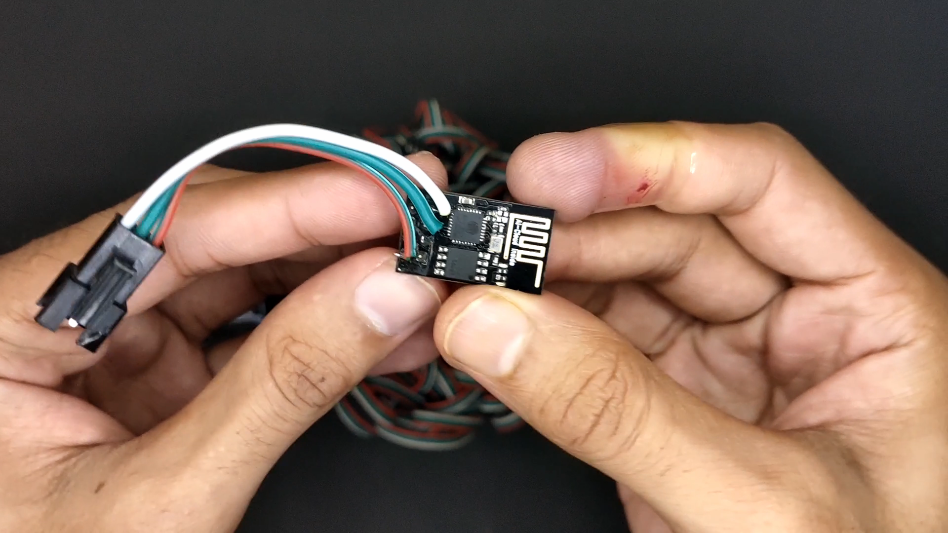
- If you use ESP8266 board then we can display time and other animations on the matrix.
-
4Assembly:
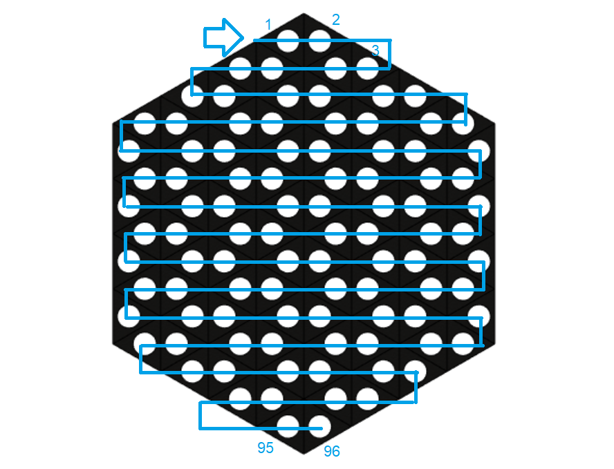
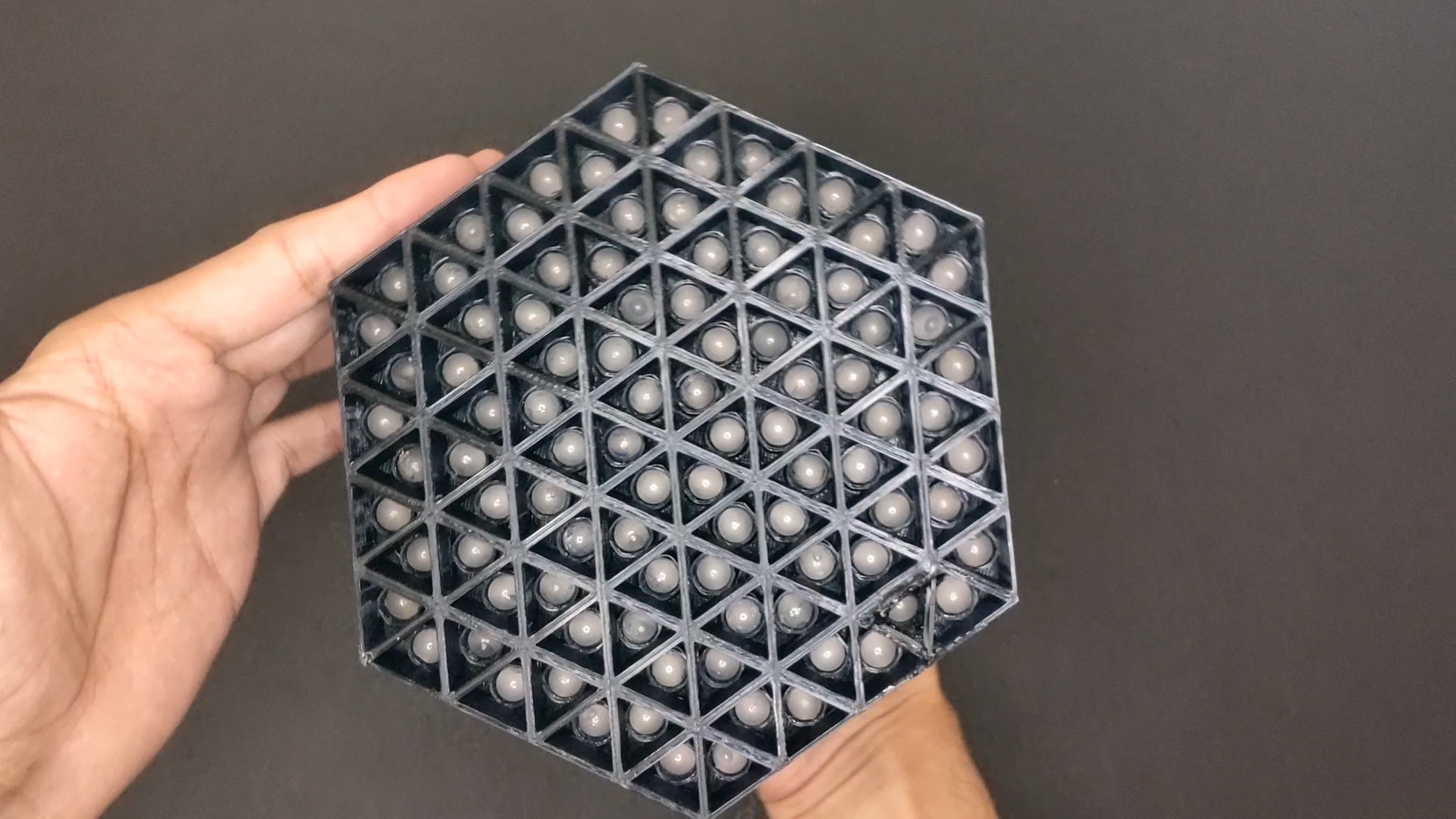
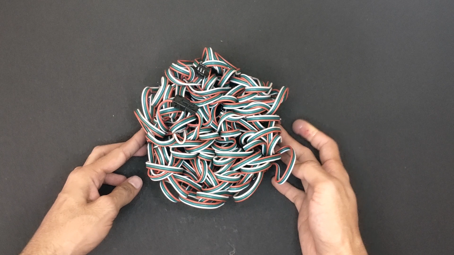
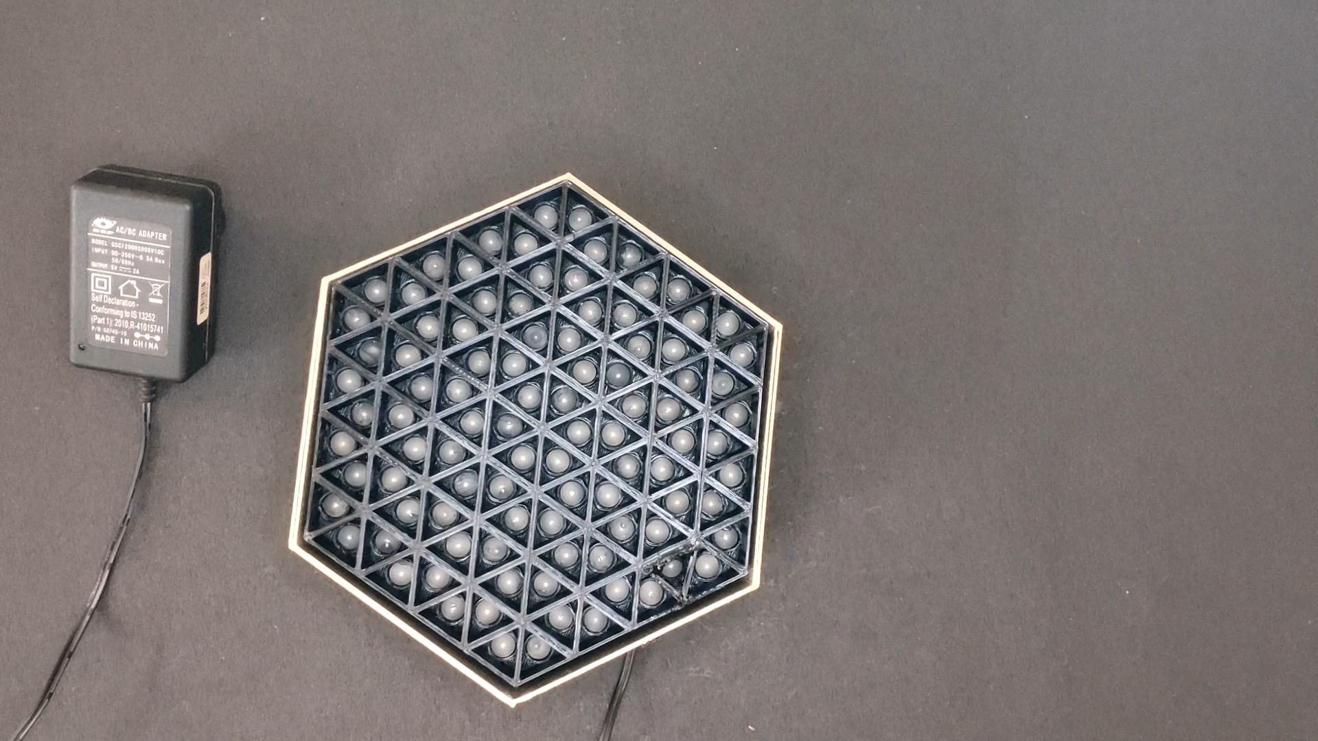
- Put all the LEDs in snake wise order.
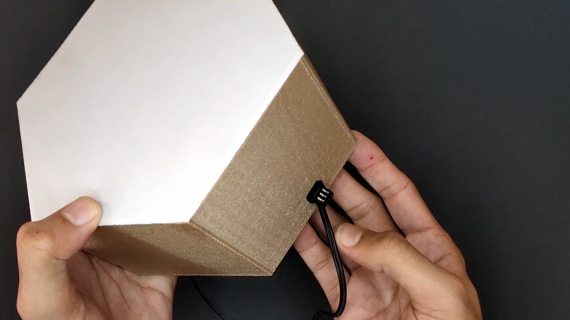
- Assemble everything together.
- Solder the connector to Microcontroller board , the connector is taken from the other end of the LEDs line.
![]()
![]()
![]()
![]()
![]()
![]()
![]()
![]()
-
5Coding:
- Click here for codes
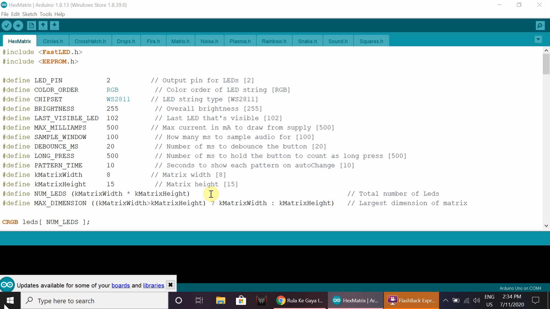
- For this matrix I have made three codes HexMatrix.ino ,clock1.ino and clock2.ino.
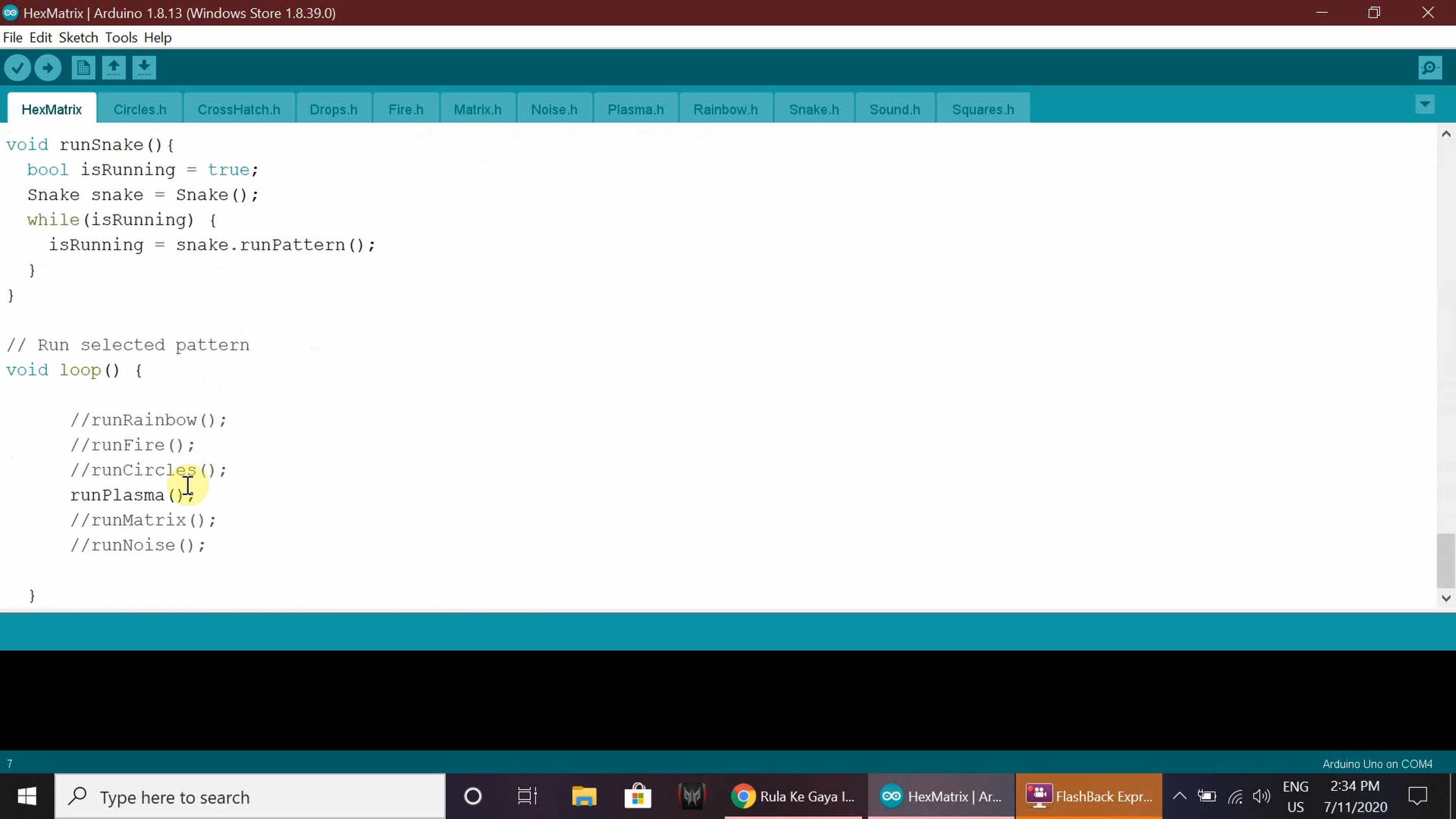
- HexMatrix code is the code for displaying animations on the matrix,it can run on any Microcontroller board.
- Clock and clock2 code only runs on ESP8266 boards.
HexMatrix.ino:
- Open the code given in Arduino IDE.
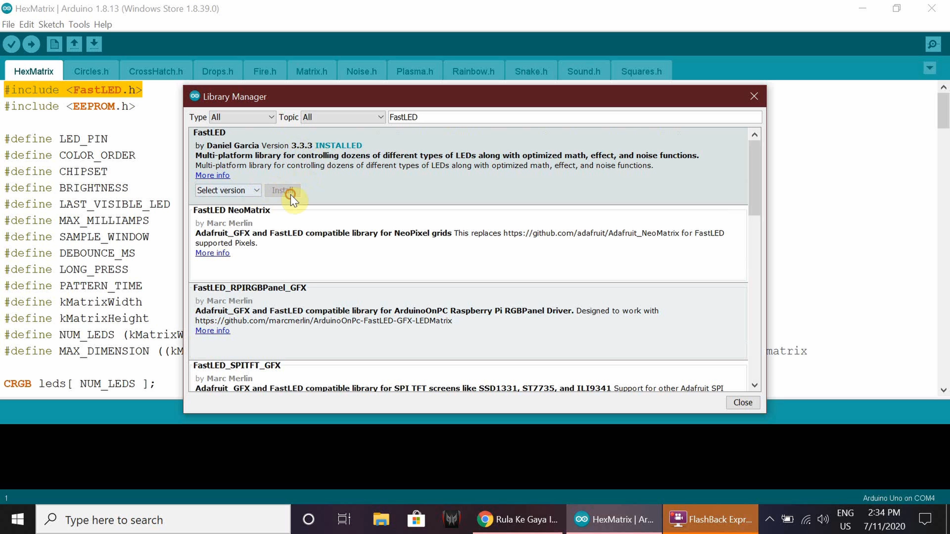
- Install the FastLED Library in Arduino IDE.
- Select the board type,port and upload the code.
![]()
![]()
![]()
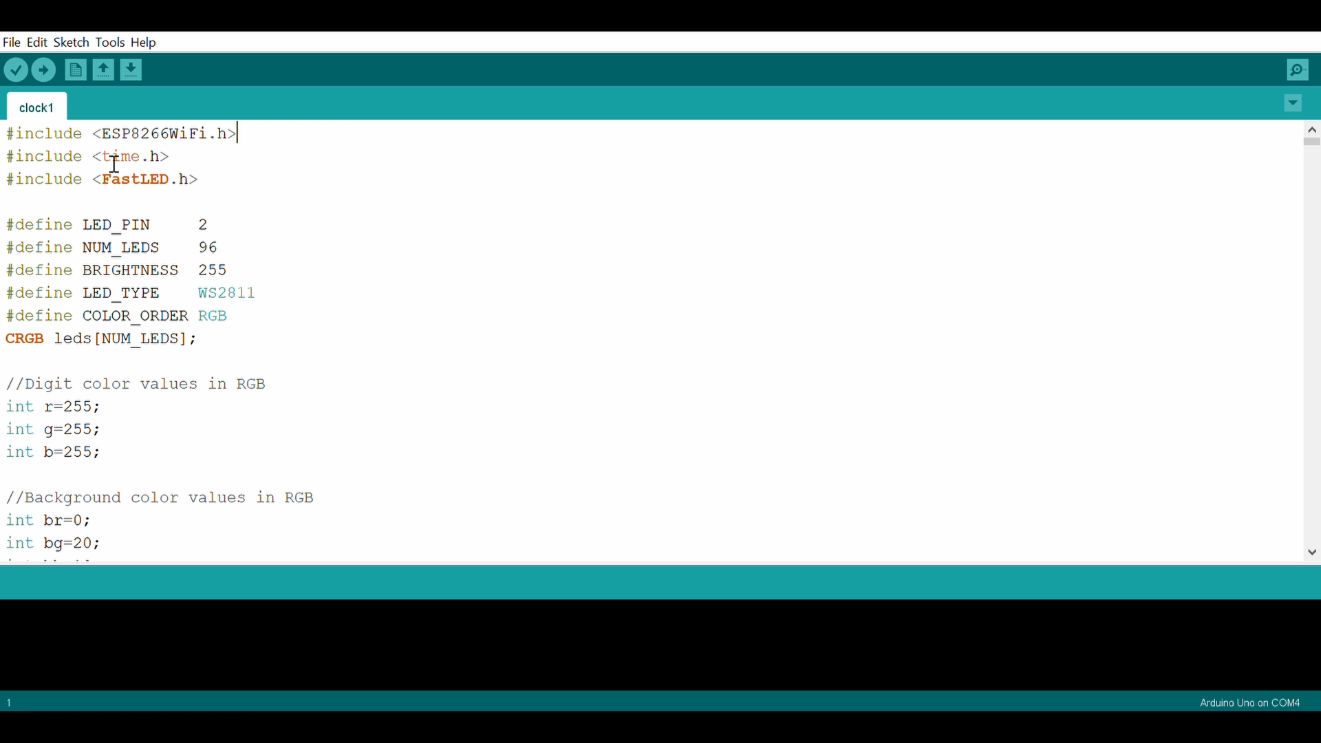
- Open the code in Arduino IDE.
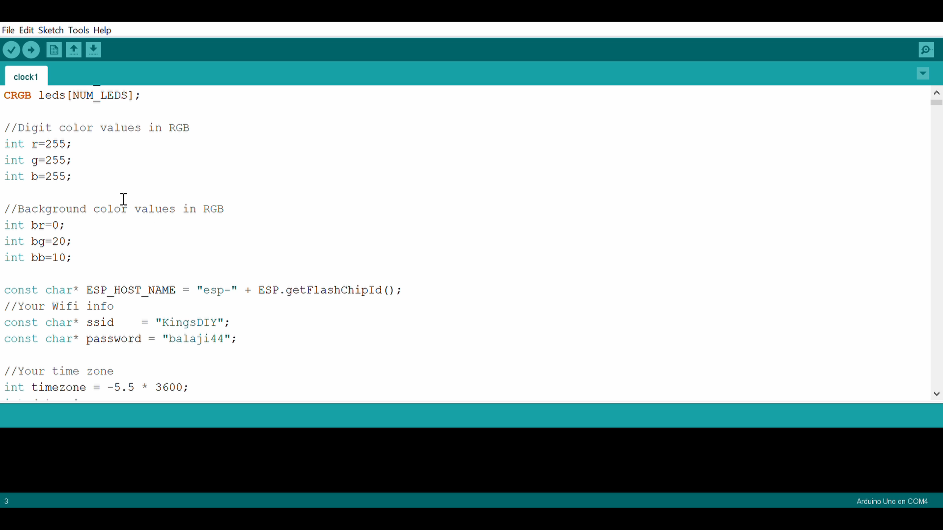
- In this code we can change this values as per our color requirement
//Digit color values in RGB int r=255; int g=255; int b=255; //Background color values in RGB int br=0; int bg=20; int bb=10; - Enter the Wifi name and password
const char* ssid = "Wifi_Name"; const char* password = "Password"; - Enter the time zone of your country(India 5:30=5.5 similarly enter your time zone)
//Your time zone int timezone = -5.5 * 3600; - Select the board type as ESP8266,select the port and upload the code.
![]()
![]() Apart from this we also have many other animations in the FastLED Examples.
Apart from this we also have many other animations in the FastLED Examples.
 Mukesh Sankhla

 Apart from this we also have many other animations in the FastLED Examples.
Discussions
Become a Hackaday.io Member
Create an account to leave a comment. Already have an account? Log In.