-
1Tools and Skills Needed
Phillips screwdriver, #6 nut driver, portable drill with drill set, two step tab connector crimper (Molex 63811-1000 or equivalent), needle nose pliers, wire cutters and wire stripper, scissors, and masking tape. You may need the Tamperproof Torx.
This is a simple modification; but does require working with line voltages. It needs basic electrician skills akin to changing a light fixture or AC socket safely. No soldering is involved. I used quick connect tab connectors which are crimped and insulated with heat shrink tubing. You need to know how to use the two step crimp tool and how to apply heat shrink tubing. If you are using a different microwave, then you need to be able to reverse engineer the wiring. Wiring this up incorrectly can lead to all sorts of badness such as electrical shock, fire, acrid smoke, property damage and personal injury. It is always a good practice to double check the wiring when done and before applying power.
-
2Tear Down
Microwave can generate lethal voltages, and as a reminder, please make sure it isn’t plugged in when you start working on it.
Remove the U shaped metal shroud over the top and sides of the microwave. These are held in by a few metal screws and one of them may be a security screw. A security screw or Tamperproof Torx screws have a metal post in the center. They are there to keep you from trying to open this up as it does contain a death ray. Of course, about every hardware store carries a cheap set of Torx tamperproof screwdriver set so you can tamper with this screw.
![]()
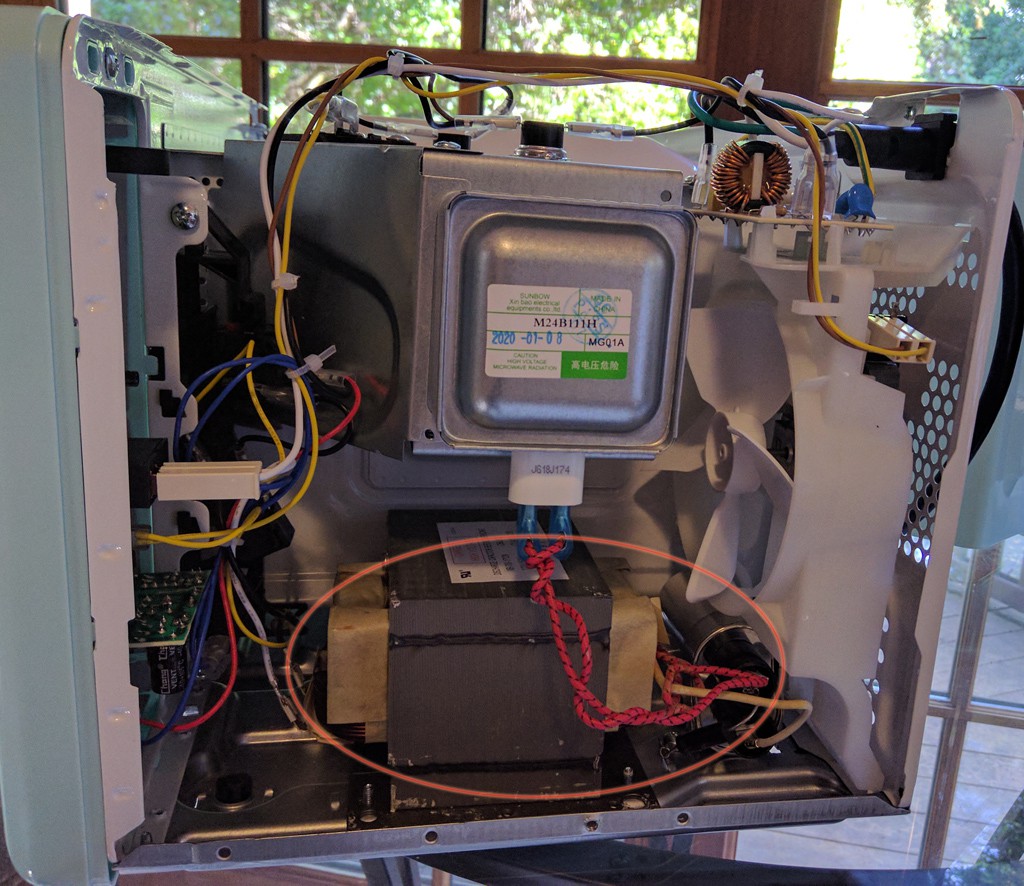
All the electronics is on the right side behind the controls. You want to disable the magnetron and make room for the ballast. Behind the controls is the control PC board with a relay which switches power on and off to a large power transformer (above photo inside ellipse) and a smaller relay for fan and turntable. The secondary of the transformer goes to a high voltage diode and oil capacitor which then feeds the magnetron. These are all connected together using 0.187in wide tab connectors.
Disconnect the female tab connectors from the transformer and the magnetron. Unscrew the transformer and oil capacitor from the case and remove them. This will give a lot of free space to put a small ballast in. The connectors were very tight and took a lot of force with good size needle-nose pliers to pull them off.
Leave the lamp, turntable and fan alone. The fan primary function is to cool the magnetron and electronics; however it does circulate air through the chamber. Since the UVC lamp will generate ozone, you will get hit with an intense ozone smell when you open the door. Not only is ozone not healthy in large doses, it smells bad. The fan will help ventilate and dilute the ozone produced. This needs to be used in a well-ventilated area.
-
3Installing the UV Light System
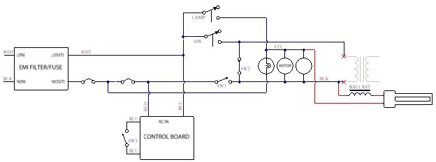
There was a convenient and well-done schematic on top of the chamber inside the microwave. Unfortunately it doesn’t actually represent the way the microwave was wired up. I had to reverse engineer a bit of it to figure out how to wire it. If you use a different microwave, reverse engineer it to figure out how to hook this up.
I put the light socket on the side with the electronics close to the top of the chamber. Put masking tape down first to protect the paint and the tape makes it easier to mark and drill. I used the socket as a template for the four metal screws (7/64in) and also marked the center of the socket for a larger hole to pass the wires through (3/8in). The metal is very thin and easy to drill but still recommend doing small pilot holes first and gradually increase drill size for a cleaner job. Remove the masking tape and deburr the holes, especially the larger hole where the wires will pass through. I put a coat of enamel paint on the large hole to help smooth the surface.
![]()
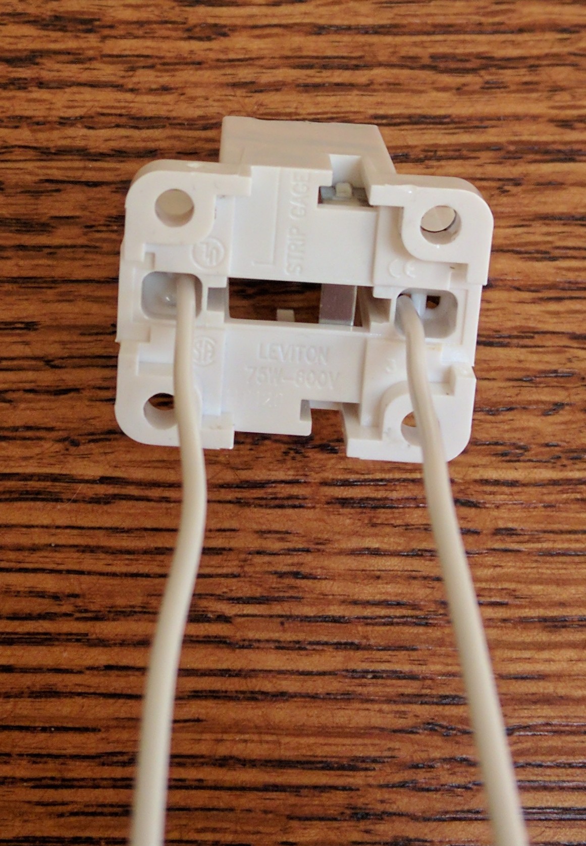
The G23 socket has a pair of push in connector holes for each contact. Since this is a two wire socket, this is a shorting pair and only one wire on each contact is required as shown in the picture. The wires are about 1.5ft long and will be trimmed once installed. The socket came with information for the type of wire (18AWG solid) and how much to strip it. I added a short length of heat shrink tubing over the individual wires and a larger heat shrink over both wires to help protect the wire passing through the hole. Once installed, a bit of silicone goo can also help keep the case from cutting into the wires. Use four #6 ½ inch screws to hold the socket.
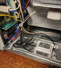
The choke or magnetic ballast is a current limiting inductor for a preheated fluorescent tube.. The ballast can mount in the same area as the transformer you removed. Reuse one of the mounting holes for the transformer and drill the second for loose fit #6 machine screw. (#25 drill 0.1495in). Use 6-32 hardware to attach the ballast to the case. Finish up by adding Loctite or lock washers on these screws so they don’t back off.
-
4Wiring for UV Tube
![]()
My instructions errs on making the wires too long. It’s easier to fix mistake with longer wires than too short. You can follow the schematic for how to wire this up and skip the detailed instructions.
Take one of the tube wires and form it so that it reaches the control board with a bend at the base of the magnetron tube and towards the control board. Cut this wire so that it just touches the control board. Strip about 3/16 in from the wire and crimp a tab male connector to the wire. The other tube wire, should go straight down without interfering with the fan. Cut this wire so it just touches the bottom case (where the ballast is attached to). Strip about 3/16 in from the wire and crimp a tab male connector to the other tube wire. Put 1 3/4in x ¼ in dia heat shrink sleeve loosely over each of the tube wires. Don’t shrink yet.
I did not cut the ballast wires except to trim back the exposed wire to 3/16 in for the crimp terminal. Crimp a tab male connector on one of the ballast wires and a tab female connector on the other ballast wire. Connect this wire to the tube wire that came straight down making sure it is firmly seated. Pull the heat shrink tubing over both tabs and then heat with a heat gun until it forms around the wire. Check that it has no exposed metal.
![]()
There are two female connectors that went to the transformer. One (white) goes to the control board MW relay and the second (black) which goes to the interlock microswitch and turntable (brown). You will also see the white load wire from the AC filter board going to the other side of the MW relay. We are not using the white one going to the MW Relay, so bend this wire over near the connector and slide a 1 ½ in length of ¼ in diameter heat shrink sleeve over it. Shrink the tubing and insure there is no longer exposed metal.
The black terminal that went to the transformer should connect to the remaining ballast tab connector. Pull the heat shrink tubing over both of these and shrink the tubing.
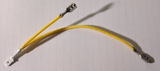
There isn’t a good place to hook into the load side of the turntable motor, fan and lamp. I made a Y connector to splice in. Cut a 1-1/2 inch piece of AWG22 wire and strip each end to 3/16 in.
![Y cable Y cable]()
Crimp a tab female connector on one side. Cut a 3-1/2 inch piece of AWG22 wire and strip each end to 3/16in. Crimp a tab female connector to one side. Crimp the free ends of both wires into the tab male connector. Cut some ¼ in diameter heat shrink to cover the connectors and slide over the end and leave loose.
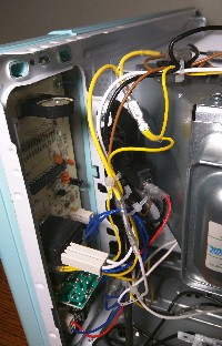
There is a pair of yellow wires next to the lamp relay on the control board.
![]()
One goes to the turntable the second goes to the lamp and fan. Pull the yellow wire from the relay off of the lamp and insert the short wire female connector onto the male lamp connector and the terminal you just removed to the male tab connector on the Y. Plug the remaining tab female connector on the Y to the remaining tube male connector. Slide the heat shrink over the wires and shrink the tubing. Again check for no exposed metal.
-
5Giving it a tin foil hat
![]()
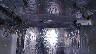
Aluminum is one of the best reflectors for UVC. Cover the top, back and sides with aluminum tape. It should not interfere with the carousel plate nor the vents. The glass in the door did not pass UVC light. I did see a large increase in intensity when we put the tape on the sides and top.
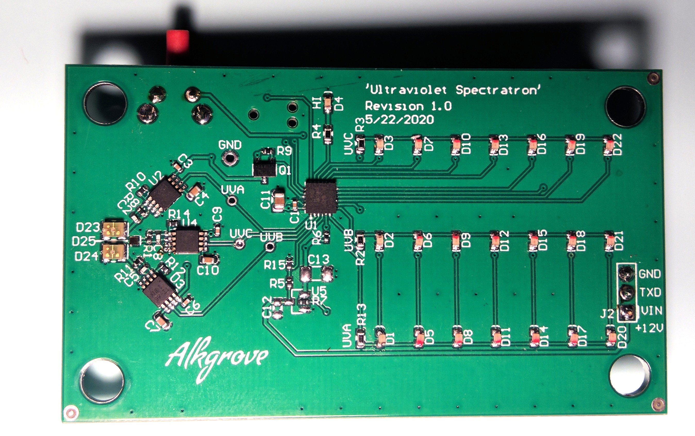
Finding good ways to measure UVC was challenging, so we came up with an instrument that we call the Ultraviolet Spectratron. It has independent photodiodes for UVA, UVB and UVC and three columns of LEDs.
![]()
 Bob Alkire
Discussions
Become a Hackaday.io Member
Create an account to leave a comment. Already have an account? Log In.