CAN Simple nodes all look pretty much alike. Only the headers on the top change. There's a tremendous amount of connectivity available on that top row, including two UARTs, I2C, SPI, PWM ports for motor drivers or servos, a quadrature decoder, a bunch of ADCs, and a complete 8-bit parallel port.
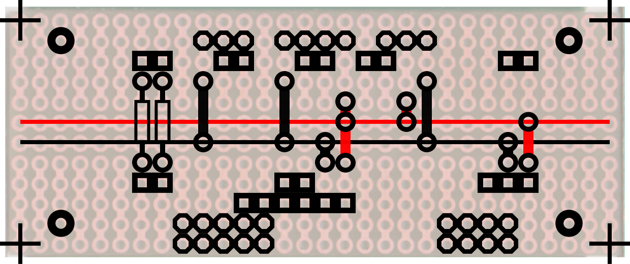
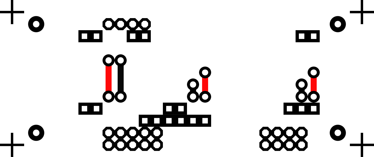
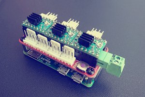
Here is the layout for my motor controllers. On left, GPIOs are pulled low with resistors to set the motor number. On the top, left to right, headers are provided for PWM, quadrature decoding, and current sense ADC.
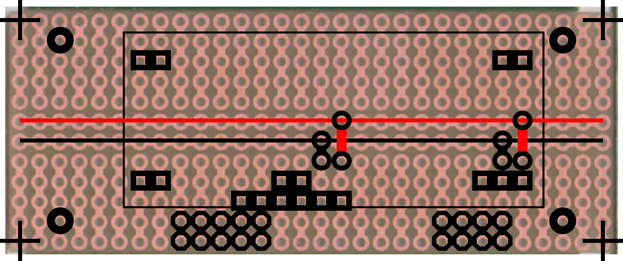
Conversely, the next layout is for my Autopilot node, which has no external connectivity at all:
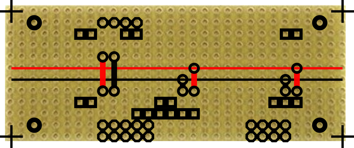
Below is the pin-out for the bottom row of all nodes.
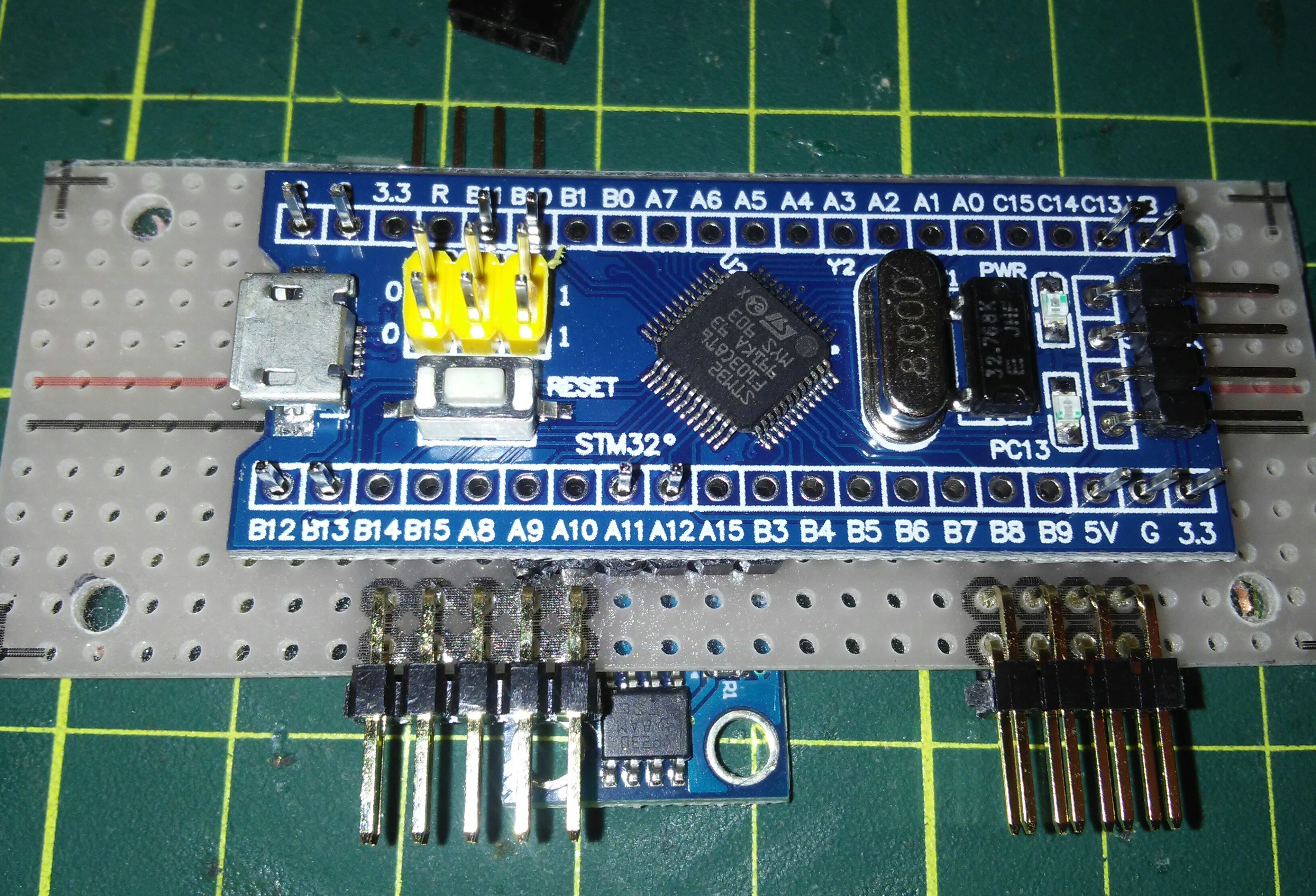
Pins at B14 and B15 are 5V and GND. These go straight through to the corresponding pins on the top and provide power to peripherals.
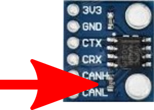
Pins at A9 and A10 are CanL and CanH.
Pins at 5V and G are 5V and GND, and provide power to the processor module.
On the backplane, the two 5V lines can be connected or can have separate power supplies.
Pins at A8, B8, and B9 have no connection, and are just there for stiffness. You can add additional stiffeners anywhere at B4 through B7.
The dual row headers on the bottom plug into a simple backplane. Dual row headers are used for stiffness.
When the nodes are plugged into the backplane the whole setup looks like this:
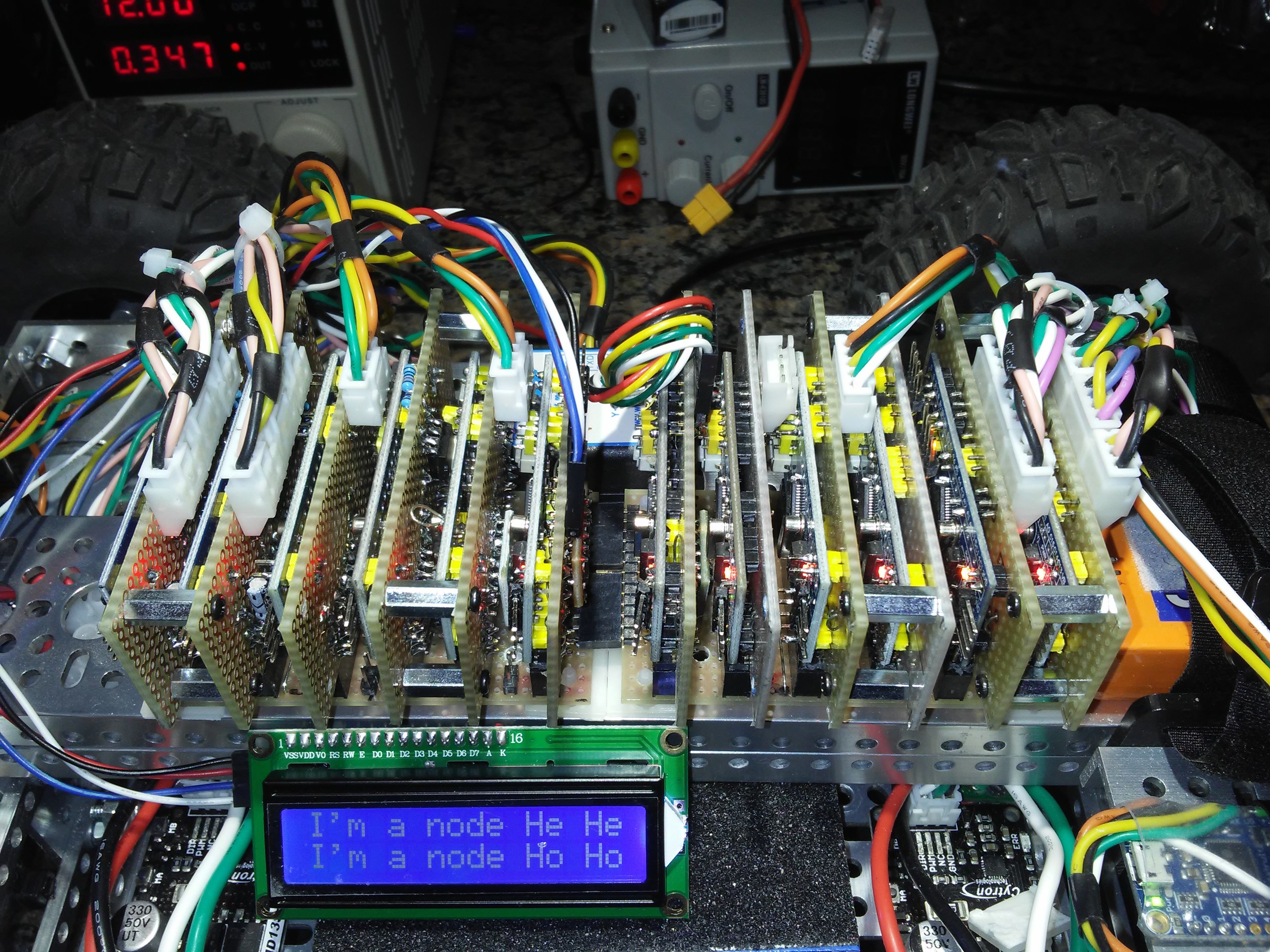
For even more rigidity, the nodes can be joined together in pairs, as in some cases above.


 h2w
h2w
 Mo Badr
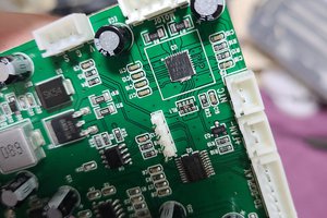
 Torbjörn Lindholm
Please share code source files.
Thanks in advance.