0%
0%
Become a Hackaday.io member
Already have an account? Log in.
Just one more thing
To make the experience fit your profile, pick a username and tell us what interests you.
Pick an awesome username
hackaday.io/
Your profile's URL: hackaday.io/username. Max 25 alphanumeric characters.
Pick a few interests
Projects that share your interests
People that share your interests


 Kevin Santo Cappuccio
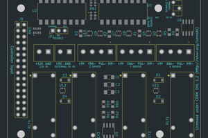
 José Júnior
 brandon
 Baruch Even
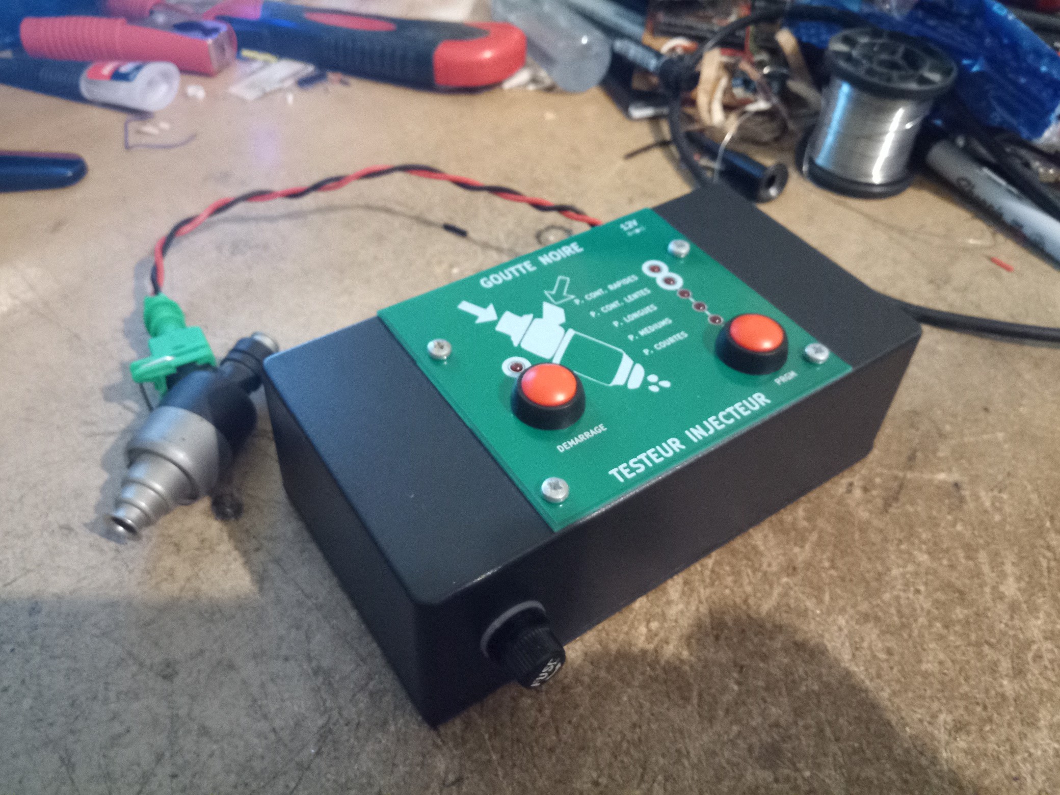
Nothing truly extravagant, the analyzer control the curl of the injector with various examples. There's a couple of unit on the chinese market however they look pretty poo with their plastic case. This unit will be made for legitimate oppressive work area with an aluminum case.
Initially I needed to make a 4 channel unit to have the option to do test design for all the injector without a moment's delay. Yet, I understood there weren't resistors yet curls that control the injector pin. On my Daewoo vehicle, the impedance is 15.4R which implies a ton of current ! (a few units are even lower) which complexifies a lot the desing on the off chance that I go this street.
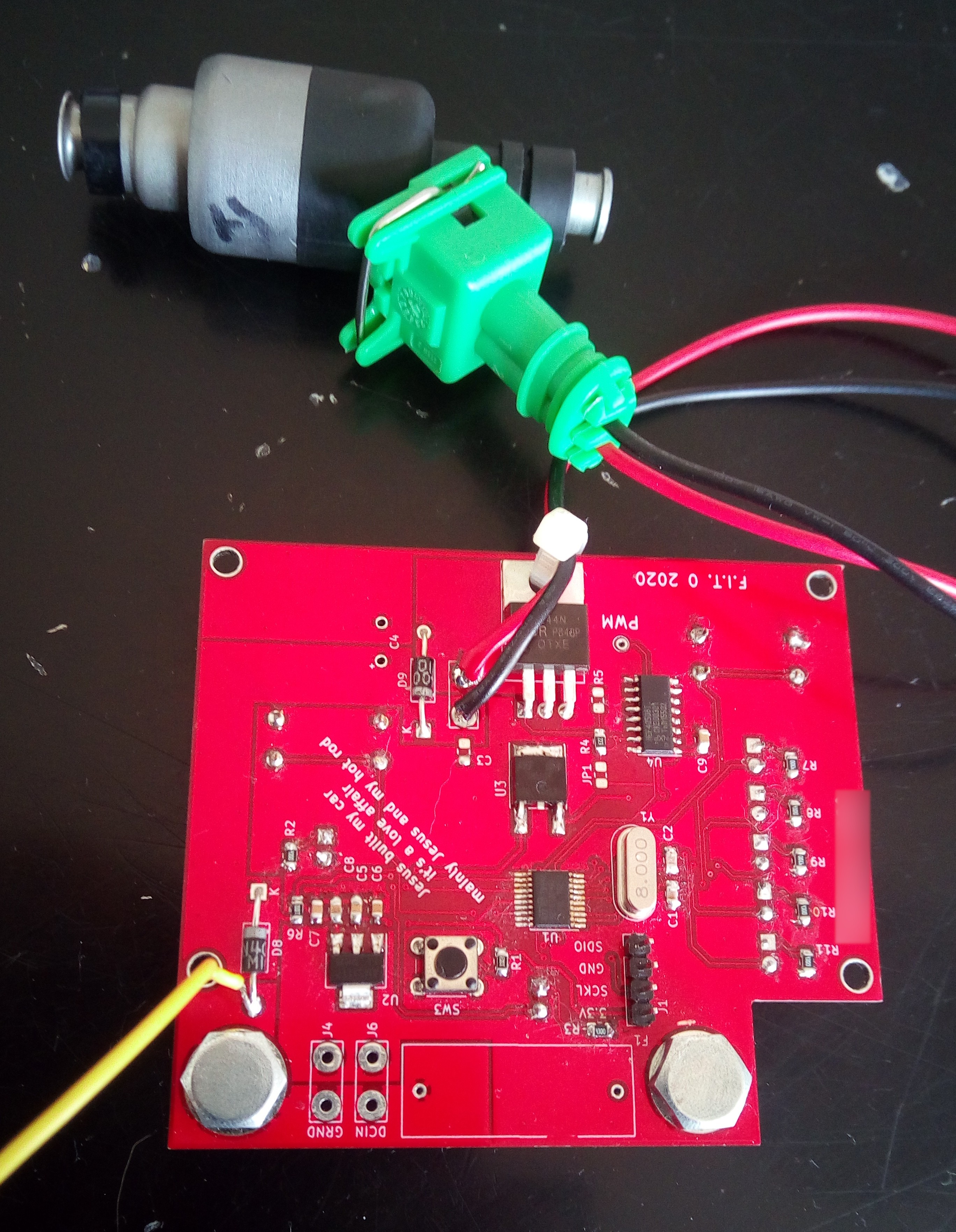
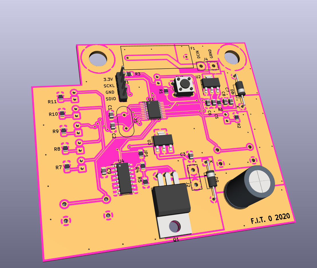
The microcontroller is a STM32F0 that I have available in its SOP20 bundle. I added CMOS cushion to have the option to utilize different sort of N-Channel mosfet to control the curl. All that will be finished with the PWM mode on the microcontroller that has a fascinating "reiteration" highlight which is precisely exact thing I need.
Right now I actually need to find documentation on the term of the beats relying upon the condition (inactive vehicle, quick motor fire up, ect...).
check out our tester
https://thericepuritytester.com/