Ken Meyer
-
I didn't win a trip to space!
10/13/2014 at 18:26 • 4 commentsOn one hand, I was hopeful, but I've really been pushing my free time to meet the competition deadlines! I'll be able to actually take a break now and again and work on other projects as my interest drifts!
I'm so close that I WILL be finishing and installing a prototype very soon, but polishing of the documentation will wait until I have something I'd want people to copy.As always, let me know if you are trying to copy my work (or any part of it). I don't need any attribution (unless you copy my revision of the Apitronics firmware that is covered under GPL 3.0) but I probably have a list of improvements and suggestions that haven't been published but could save you a lot of time!
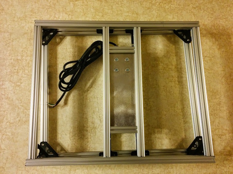
In other news, I have a frame built around a load cell! I want to replace the cheap little washers with spacer plates for more stability, and I'm a bit concerned about how much the system can bend, but I'll test it out with a dummy hive first and make sure that it's not too bad before installing it semi-permanently.
![]()
Again, I don't really recommend using OpenBeam for this application (although it could probably work with some additional cross-beams) but I'll learn a lot from it before I jump into a welded frame.
On the electronics side, last night, I was about to put together a circuit to drive the load cell at 10V when I realized I need an inductor I don't have on hand -- I really should read datasheets more carefully BEFORE ordering components...
-
Change in Load Cell
10/09/2014 at 01:49 • 0 commentsIt'll be a couple days until I know if I made it into the final round of the Hackaday Prize competition, but in the mean time, I've made some great progress toward a better scale.
I've been very unimpressed with the temperature sensitivity of the cheap postal scale, especially when I had much better results with the $160 Adams postal scale, so I've always wanted to mount my own load cell on a simple frame. However, I really don't think wood will be strong enough to handle the 400+ pound load, especially considering transient loads when heavy boxes are heaved onto the hive, and given that the load cell is mounted top and bottom on a cantilevered 1" square.
My plan has always been to get a metal plate welded into a steel frame of square tubing, but that involves either a few weeks of learning basic welding or begging for friends to help. Somehow I saw a reference to OpenBeam, a kickstarter open-source aluminum extrusion system, and I picked up the pieces I'd need to build a frame for my scale!
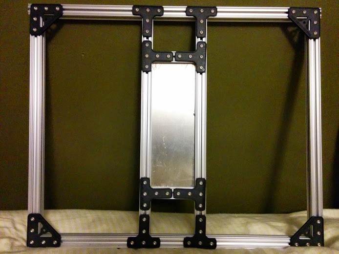
Here's the frame with the aluminum plate slotted nicely into the extrusion and supported on all sides. I originally tried an H configuration, but found it to be awfully twisty so I added additional cross pieces at the top and bottom of the H. The extrusion isn't exactly cheap, but it gives me a lot of flexibility in prototyping (for example, quickly and easily adding extra bracing) that I wouldn't have if I had jumped straight to a welded piece.
![]()
I had the 1/8" aluminum plate machined for me to the right dimensions from http://OnlineMetals.com. As is often the case, I don't really have the right tools for machining easily available to me, and they (along with other machining services) make life a LOT easier for this kind of prototyping!
I still need to pop 4 holes in the aluminum for mounting the load cell, bolt together the second frame (one above, one below the load cell) then it'll be ready to test it out. Here's the load cells I'm using. The aluminum plate is sized to be about 1" wider than the load cell, and the width was tweaked to 2.65" to match the length of those precut small pieces I got on Amazon.com.
I also quickly ordered some regulators from Digikey to increase the excitation voltage. I'm bumping the 3.3V up to 12V, then using a 10V voltage reference to drive the load cell. I'm still worried about drift between the HX711 and the voltage reference adding to the error, but in a final design, I'll need to test out a few designs. Off hand, I'll probably try using temperature-stable resistors in a voltage divider (as long as any temperature variation is consistant, I should be able to remove it in software), try a 5V reference that can be used directly in the MCP3551 22bit ADC.
In short, while I might have a system running very soon, I've got months of testing to find the best configuration before I really settle on a design (at which point, some brilliant EE will likely jump in and show me how it really SHOULD be done) but I'm very close to deploying a system that actually collects data!
-
First Signs of Temperature Sensitivity
09/29/2014 at 01:14 • 0 commentsAfter I got the HX711 working for the first time (after days of last-minute debugging code -- such a great feeling at the end!) I immediately walked away from the project and let it collect data for a couple of hours. The scale and Apitronics Bee were both sitting on my concrete basement floor, but since the scale has a metal housing, and the Bee is in a plastic box, the scale obviously responds to temperature changes much faster than the Bee.
When I looked back at the data, I was at first shocked at how unstable the weight reading was, but when I looked closer and compared the weight data to the temperature data, I found that the weight dropped and the temperature started to slide down just at the point where I turned the air conditioning back on because we were all roasting after cooking for a party!
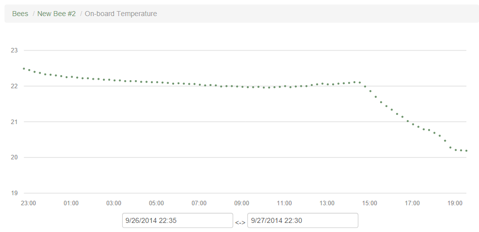
Here's the temperature data (degrees C. on the vertical axis, time on the horizontal):
![]()
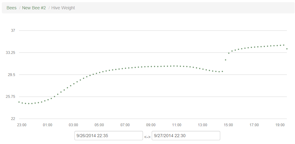
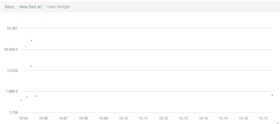
That elbow at 15:00 is right when the air conditioning kicked in. Now here's the weight reading (pounds on the vertical, time on the horizontal):
![]()
The weight of the hive was pretty steady after an initial rise that may be a combination of temperature and relaxation after loading the scale with 30 lbs, however, the sudden jump of 4 pounds when the A/C turns on is huge!
If I'm interpreting the shift right, I've seen much more stable behavior in a more expensive scale, so I'm leaning toward using a large stand-alone load cell right away. I'm also quite unhappy with using an excitation voltage of only 2.8V for the postal scale when I could get almost 4X the signal (vastly improving the signal to noise ratio) by adding a regulator and bumping the voltage up to 10V.
Just in case I make it to the next round of the hackaday prize competition, I think I'm going to get a new HX711 board (I fear the current one may have been compromised by some excessive soldering work) and mount it properly in the Apitronics Bee. If I make it to the next round, I will spend the next month characterizing the system and try to compensate for temperature factors by the new deadline at the end of October so I can have data from a real hive, even if it's less accurate than I'd like.
If I don't make the next round of the hackaday prize competition, I think I'll step back, finish my design of the single-load cell scale, add the 10-12V regulator (paying careful attention to temperature sensitivity of the chosen regulator!) and significantly clean up the HX711 library so I can remove all the disclaimers about what NOT to do in a proper driver!
-
Video: Demonstrating Uploaded Data
09/29/2014 at 00:41 • 0 commentsI wanted to demonstrate uploaded video, but between the difficulty of recording the computer screen and the extra 4 minutes, I couldn't fit it into the official hackaday prize competition semifinals video.
As I mentioned in the video, I'm not too concerned about short-term zero drift when the scale is suddenly loaded, because it's very rare that the beehive will experience a quick change in weight. It's mainly just during inspections when I might add or remove a box, and when I process the data for a long-term trend, I can simply throw out the first few datapoints after a load change.
-
Video: Update on Honeybee Hive Monitoring Prototype
09/28/2014 at 20:31 • 0 commentsHere's a quick update video on the status of the Honeybee Hive Monitoring Prototype. It's under 5 minutes to meet the requirements of the Hackaday Prize competition rules, and I think it's a good summary of where the project stands and some of the future changes that will significantly improve the system's performance.
I'm back on 0.75 MB/s upload speed after switching from a nationally renouned cable company (in the US) to a regionally dominant phone company after I got fed up with supporting questionable business practices by the cable company and barely faster speeds.
That said, as soon as my next video finishes uploading (hours from now), I'll add an update with a link to the video demonstrating that my system is, in fact, sending data via 900 MHz XBee from the Apitronics Bee module to the Beaglebone Black Hive, making it available on the local network via a webpage interface written by Apitronics.
-
Added Github Repository (Licensing is Hard)
09/28/2014 at 01:37 • 0 comments[EDITED 28 September 2014 to replace reference to a CC license with the GPL 3.0 license after Apitronics added the GPL3.0 license to their github repository]
Here's a repository for my edited Apitronics code. I added a lot of disclaimers in the AHX711 library -- don't use that except in an emergency (or as a reference, I suppose, I did point out what not to repeat, like defining pins in a driver)! It works, and my priority is to finish documentation for the hackaday prize competition rather than focusing on code that's a few steps beyond my comfort level (and which will break if I look at it funny, much less try to fix my bad coding practices).
In other news, open source licensing is hard! I've followed open source software and hardware for years, I've read licenses, and I'm fully on board with the goals of open source hardware and software! That's one of the big reasons I backed the Apitronics Kickstarter since their designs and software are all open source too!
That said, supporting a movement is different from trying to comply with copyright law myself, and I have a lot of uncertainty about the details.
The short version is that the Apitronics Bee software is licensed under GPL3.0, a license designed to preserve the following "freedoms" (from this quick guide to GPL 3.0)
Nobody should be restricted by the software they use. There are four freedoms that every user should have:
- the freedom to use the software for any purpose,
- the freedom to change the software to suit your needs,
- the freedom to share the software with your friends and neighbors, and
- the freedom to share the changes you make.
-
I Wrote a Working Library!
09/27/2014 at 01:17 • 0 commentsIn my last update, I had just about given up because adding to the Apitronics Bee code seemed too difficult in the time I had remaining. I actually "gave up" repeatedly, but being an engineer, I just kept thinking about the problem, and I was lucky to be able to take today off work (with a wife who let me lock myself in the basement!) and I got the system working!
It's a messy prototype, but that's fine, and I've got a wonderful (although unscaled) graph of data from a load cell below! The peak on the left is where I pressed on the scale to get a higher reading!
![]()
Scaling should be relatively straightforward and I'll finish that tonight. Then I'll spend the rest of the weekend documenting the prototype for the hackaday.io prize competition. It's down to the wire, and I've got a lot of work to do, but with the prototype running, I don't have to fight with how to write up build instructions for an incomplete project!
-
Foiled by Drivers!
09/21/2014 at 22:16 • 0 commentsI've got everything ready to integrate. I should be able to just slip the HX711 board into a Apitronics Bee enclosure, and bogde has written a lovely, open source HX711 driver with examples here, but the Apitronics Bee firmware has drivers that simplify programming a bit TOO much. Back when I was taking C++ classes, this wouldn't be a problem, but I've forgotten too much to just slip a new sensor into the BeeCore firmware (even sloppily).
That's not the end of this project! I'm sure the Apitronics folks will help me get it working when they have time, and I could probably figure it out within 2-3 weeks on my own, but this might be as far as I get by a week from now, September 29, the Semifinal deadline for the Hackaday Prize.
I'm going to keep plugging away, and I'll update the rest of this project page to reflect my current progress.
In case anybody wants to help with the programming on short notice, I'll describe what I think needs to happen.
In the HX711 example (here) I want to use the function "scale.get_units(10)" to get the average of 10 measurements from the HX711 board. I think this function needs to be written into a driver, along with the definition of HX711.DOUT and HX711.PD_SCK using this function, "HX711 scale(A1, A0);"
The firmware on the Apitronics Bee will be a modified "BeeCore" and the HX711 driver needs to follow the form of the other sensors, for example the WeatherPlug.
The current code is as follows from BeeCore (I'll want to add a 3rd sensor, the HX711):
#define NUM_SENSORS 2
Sensor * sensor[] = {&onboardTemp, &batteryGauge};Sensorhub sensorhub(sensor,NUM_SENSORS);
Finally, here's the code in void loop() that actually samples the sensors. It's been so simplified by the drivers that I can't just slip in a number at the end of an array. I really appreciate the programming work here, I'm just over my head trying to learn or re-learn (sometimes it's hard to tell which) how to modify it to do what I want.
//this if statement just samples if( clock.triggeredByA1() || buttonPressed || firstRun){ Serial.println("Sampling sensors"); sensorhub.sample(true); clock.setAlarm1Delta(0,15); -
Modifying the HX711 Breakout Board for 3.3V operation
09/17/2014 at 01:32 • 1 commentI had a great project update ready this weekend, but when I stopped working on it for a while to attend to real life, my computer decided to reboot (even though I have it set to manual update only!). I suppose that's the price for using an alpha service like this that doesn't allow draft updates!
Anyway, I'll give an abbreviated update (and I'll probably add some more minor updates instead of trying to write out complete little articles).
As I mentioned before, the HX711 breakout boards I've found work at 5V. That's fine for many applications, but the Apitronics Bees run at 3.3V, and for the prototype, I don't want to mess with other voltages. This will cut the resolution of the system since the signal from a load cell scales linearly with the excitation voltage whereas the noise floor is likely to stay roughly constant. However, adding a higher voltage (probably 10-12V just to energize the load cell presents another set of complications. The resolution is technically going to be higher, but without really careful engineering, the temperature sensitivity could get out of hand if the 10V regulator drifted relative to the 3.3V regulator in the Apitronics Bee, or worse, the 1.25V voltage reference in the HX711 chip.
I'd rather lose sensitivity in my early prototype than have additional complex temperature coefficients, so I'm going to just drop the HX711 excitation voltage to 3.3V for now.
Another, less temperature-sensitive method would be to run the board at 5V (the HX711 chip can't take more than 5.5V) and simply use a level shifter board to get the signal back to the Apitronics Bee, but again, if I can manage to do this prototype without adding more regulators and breakout boards, I'll keep it simple at the expense of some resolution.
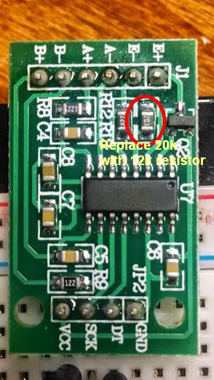
![]()
Here's a picture of my breakout board showing the resistor that needs to be swapped out with a 12k resistor to drop the excitation voltage (E+ to E-) from 4.35V down to around 3.1V (at least 0.1V below the input voltage of 3.3V). This is based on the equation in the HX71`1 datasheet that gives voltage as VAVDD=VBG*(R1+R2)/ R1. Note that this equation in the datasheet is wrong and gets the simple voltage divider backwards -- R1 and R2 should be swapped either in the equation or in figure 1 (!) to get near the measured 4.35V rather than well under 2V.
A quick calculation (with the error corrected) shows that swapping the 20k Ohm resistor (R12 on the board and on the schematic here) with a 12k Ohm resistor should drop the voltage to 3.1V. I pulled out my trusty soldering iron and Voila, the voltage dropped to 3.14V, just as expected!
Another quick note: while this breakout board is usually marketed as a 5V board (mainly due to the values of R12 and R13, there's no reason it won't work at 3.3V since the HX711 is well within specification at that voltage. I'll admit, it's possible there's something I haven't thought of that will cause a problem when I hook it up to the lower voltage, but I'll give it a quick test with a protected voltage supply before hooking it up to the Apitronics Bee.
[EDIT 27 Sep 14] I noticed that the input voltage can droop to as low as 3.0V for some reason. It could be an issue with the power regulator, or some excessive resistance in my setup (which includes a cheap breadboard) or maybe my cheap multimeter is off. Still, I wanted to be safe, so I swapped out the 12k Ohm resistor I put in for a lower, 10k Ohm resistor for an excitation of around 2.8V.
-
Choosing the HX711 over the MCP3551
08/21/2014 at 01:39 • 0 commentsFrankly, the choice of high resolution ADC was primarily due to my having trouble with PIC programming! I had a program that was very close to what I needed, and I could trigger the MCP3551 to take a measurement and verify that the data was being sent back to the PIC with a logic analyzer, but I just couldn't get the PIC to read the data, and I didn't have the hours of dedicated debug time to find the solution.
Here's a video showing the board I designed in KiCAD to hold a PIC microcontroller and the MCP3551 (as well as various regulators and connectors) along with the HX711 board I am ultimately working with now.
Honeybee Hive Monitoring
Recording weight, hive temperature, and weather data toward better management and understanding of honeybees.