-
50Watt to 70Watt Upgrade
10/06/2022 at 23:28 • 1 commentHi All,
It's been quite a while since I checked in on this project, but realized there was a super cheap upgrade that is almost a 'why not' for anyone with decent soldering tools!
So the TPA3116D2 is rated at 50W into 4ohms, and in that same family of amp chips is the TPA3156D2, which is 70W into 4 ohm.... it's a drop-in replacement, just has 20W more power with the same exact specs.
(highest upgrade that seems available as a drop-in replacement)
You do need a decent hot air station (or something similar) in order to heat the chip up enough to remove it, and because there's a good amount of GND connections to the chip and gnd planes under it, you really need to heat it up high.... I'd recommend 350C or higher... I was at about 325C, and it wasn't quite enough, I ended up damaging a small trace being a bit too aggressive and i didn't get enough solder good and melted...
You can get the TPA3156D2 for about $4-5 or so, I just bought a pack of 5 from mouser...https://www.mouser.com/ProductDetail/Texas-Instruments/TPA3156D2DADR?qs=W0yvOO0ixfHhsPcFy51aQQ%3D%3D
I did a quick test with a DB meter on my phone, about 6 inches away from the speakers, running a few acoustic songs, and then did the same test with the upgrade, looks like at least a 5db increase at least at full volume, seems good to me!
** note: the increase may even be much more than that, I realized I didn't even have my bluetooth source volume pushed up... so it gets super loud now :)
**
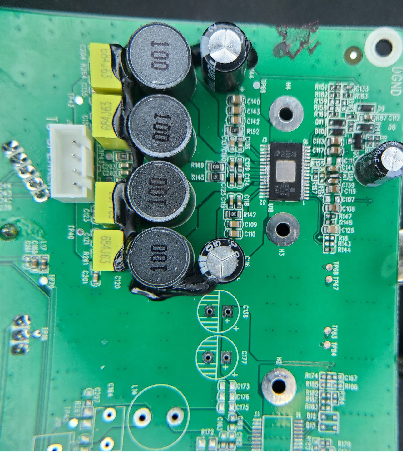
you definitely want to use a good amount of flux to clean up the pads after the chip removal (ie flux and copper braid)... and then use a good bit of flux when soldering, to help prevent bridges!Pic of the original TPA3116D2 (heat sink removed)
![]()
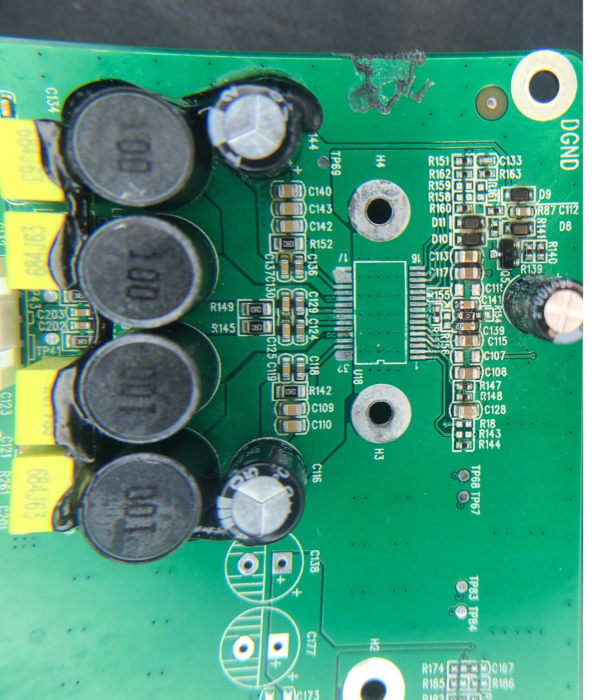
Pic of the board with the chip removed (notice the small damaged trace from not enough heat and me being too aggressive..
![]()
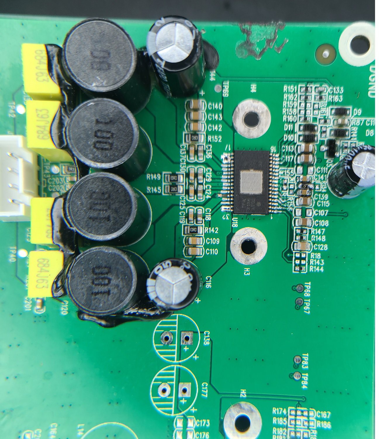
Final pic with the TPA3156D2 installed (before applying new heatsink compound along with heatsink)
![]()
-
Speaker Replacment
09/12/2020 at 02:21 • 3 commentsWell,
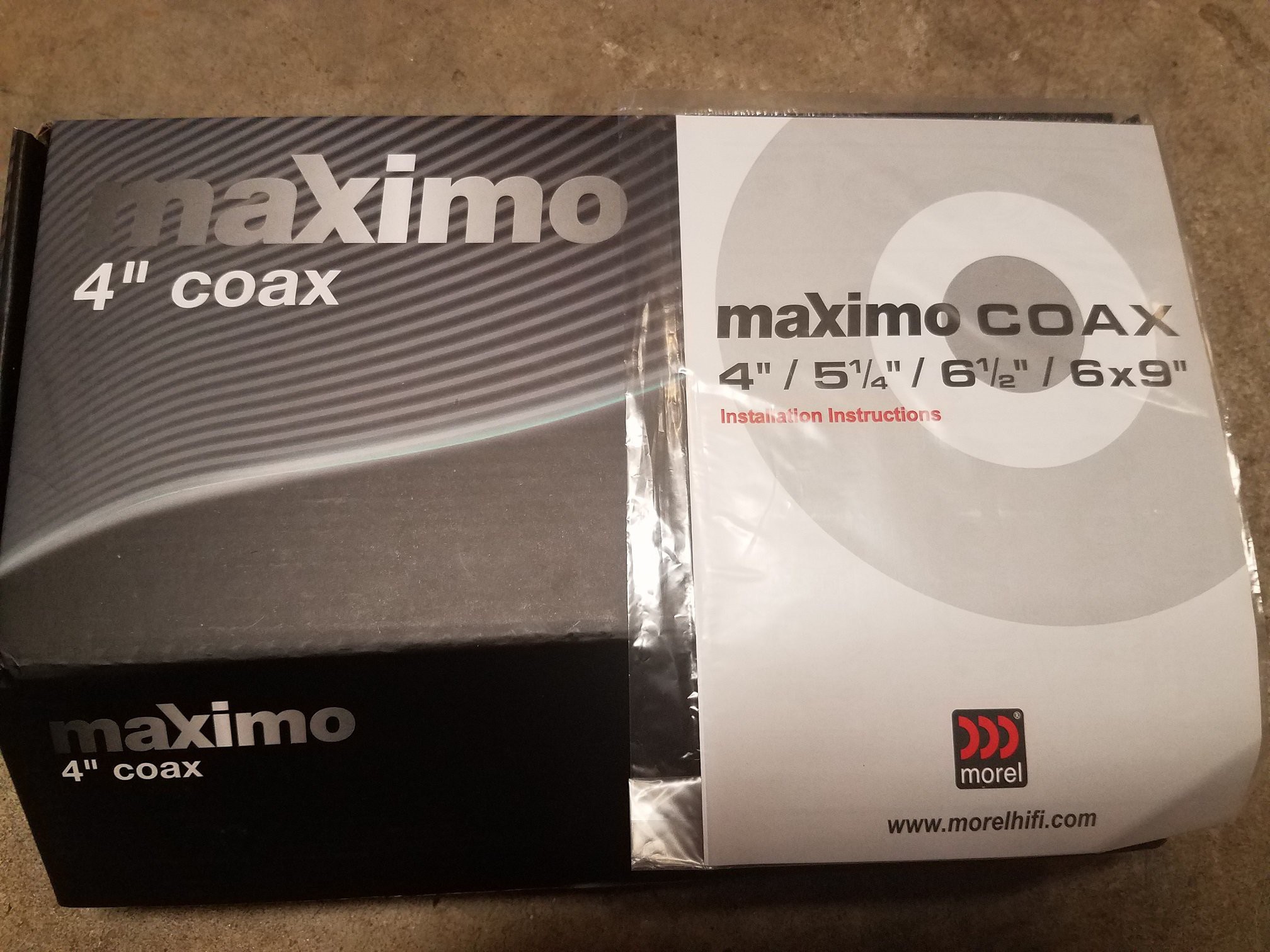
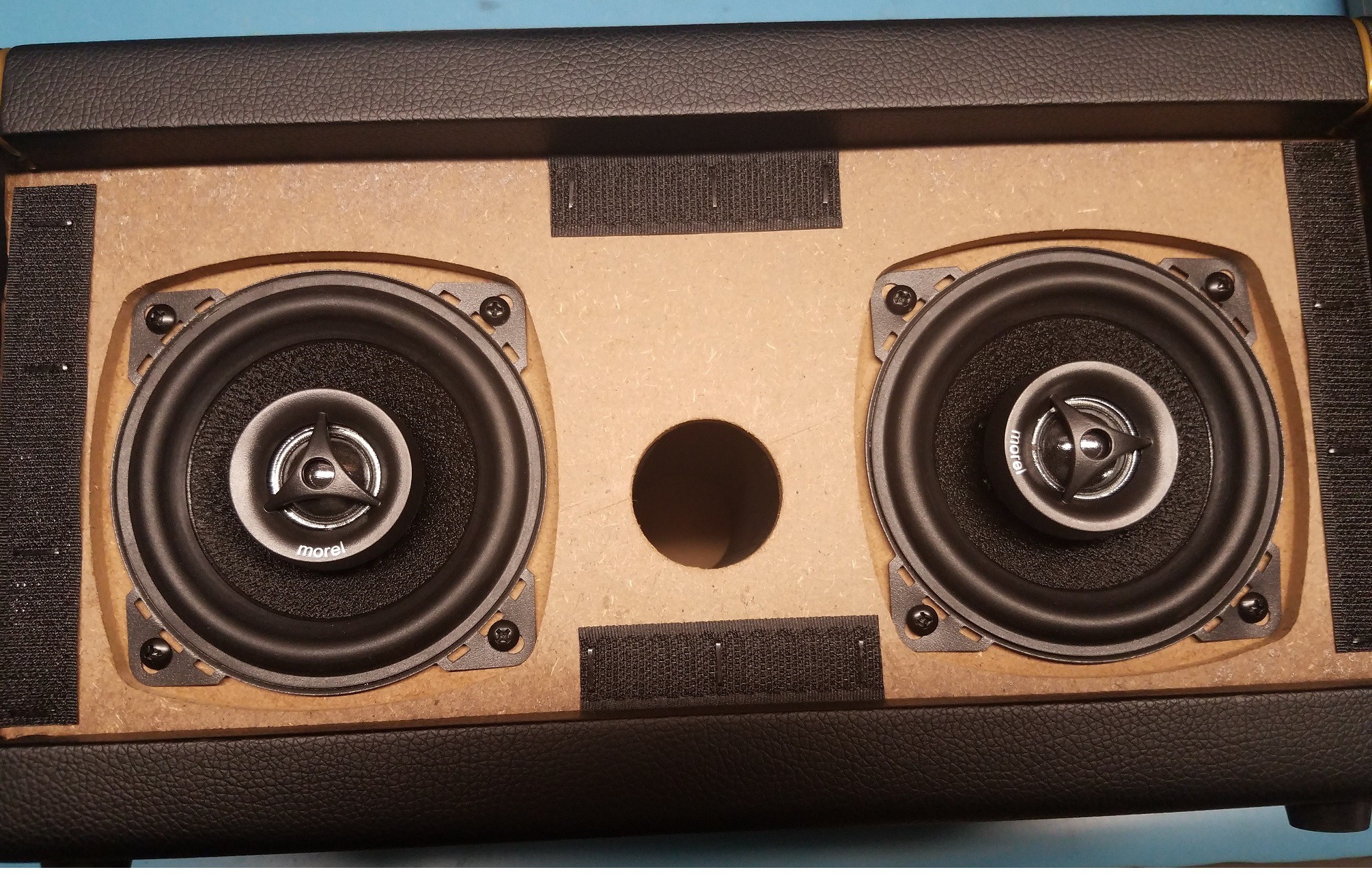
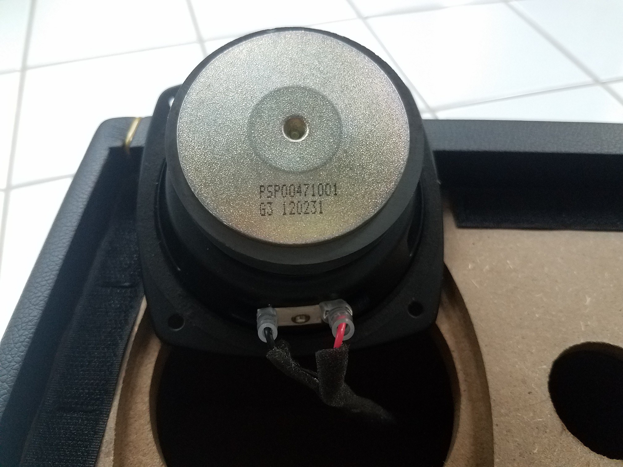
I decided to try out these Morel 2-way car audio 4" speakers, as they looked to be the right dimensions. And voila, they fit perfect, even the mounting holes lined up just enough to use the already existing screw holes.
https://www.crutchfield.com/p_210MAXIM4/Morel-Maximo-Coax-4.html
Even the crimp connectors are the standard for these car audio speakers, so it was a quick removal of the old ones, and install the new ones, 30 secs to replace each.So, adding these speakers definitely added much more high range, the treble is much clearer and streaming music sounds so much better...
BUT, I do feel the amp in this unit is really underpowered for the design. You really can't get it that loud, if it just had at least another 25W per channel I think it would be so much better. Anyhow, even though it doesn't get real loud, it did really clear up the sound spectrum...
![]()
![]()
-
STM32F4 - Processor Module
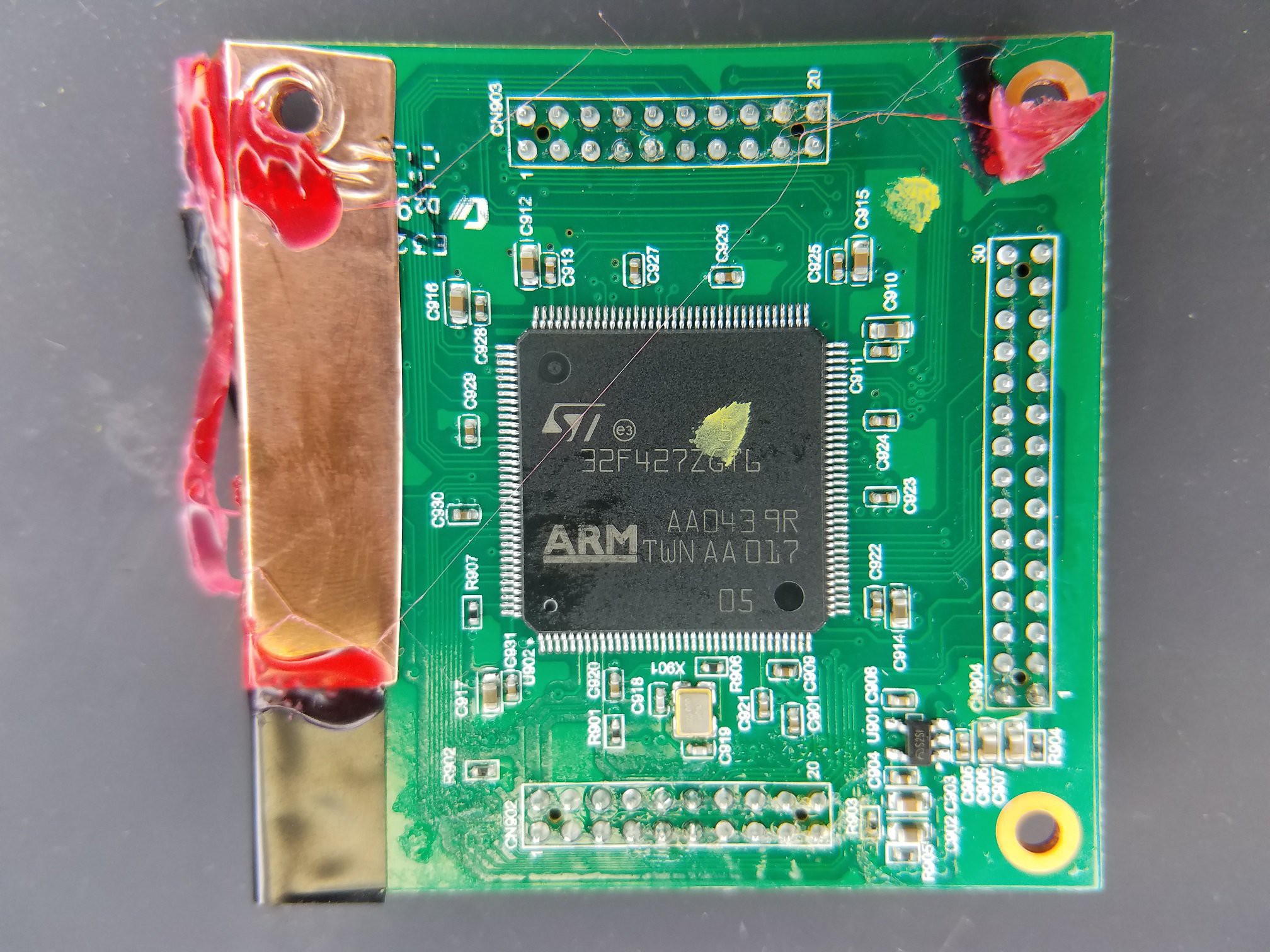
09/02/2020 at 17:54 • 1 commentThe Spark 40 uses the STM32F427 as the main CPU of this amp. The processor is mounted on a 'removable' pcb module, using standard .050" (1.27mm) M/F headers for the ease of removing the module from the main PCB.
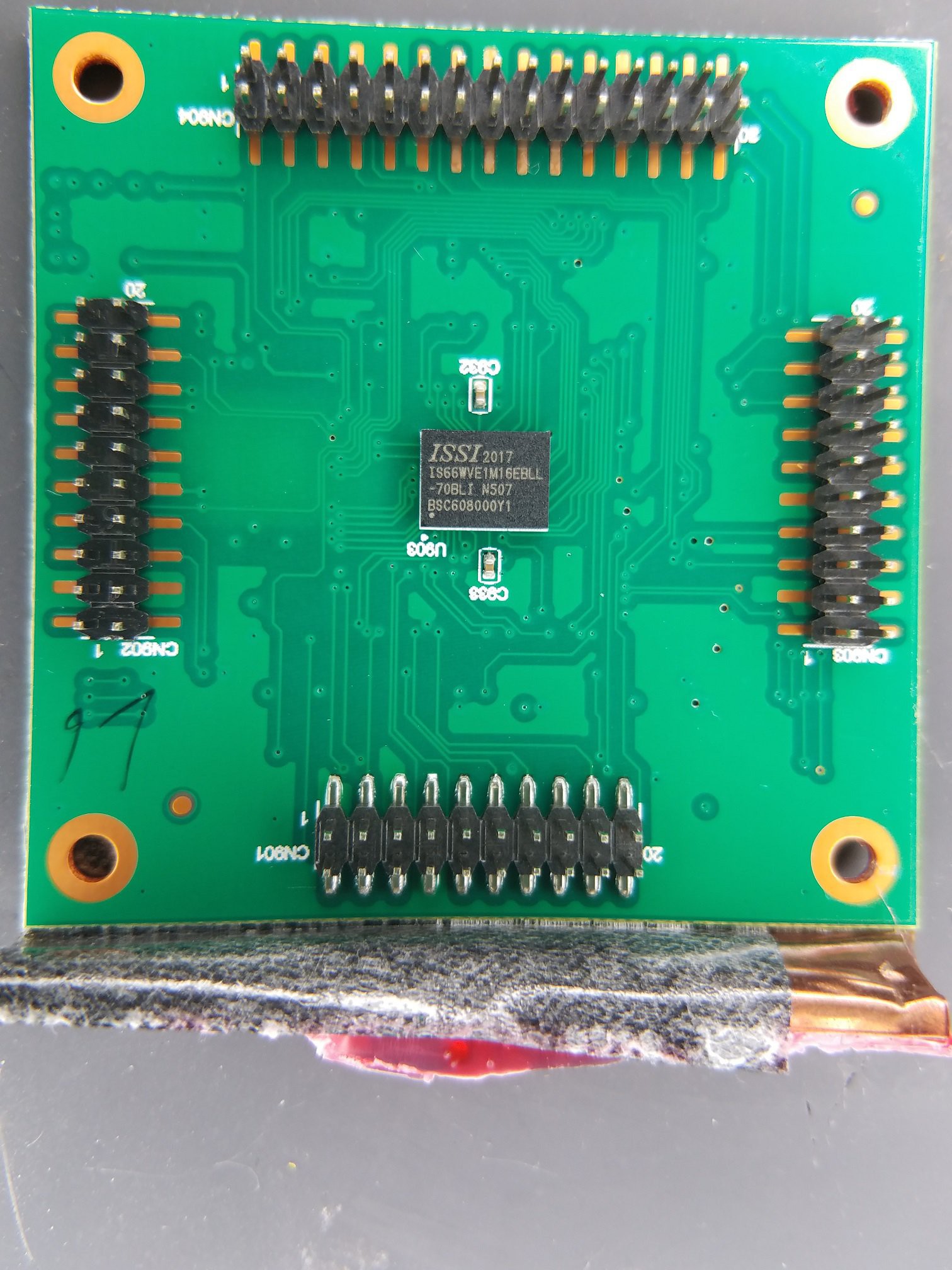
On the underside of the processor module is the ISSI 16Mbit (2MB) SRAM, added on for extra external SRAM to the CPU, since the STM32F4 really doesn't have much internal SRAM.
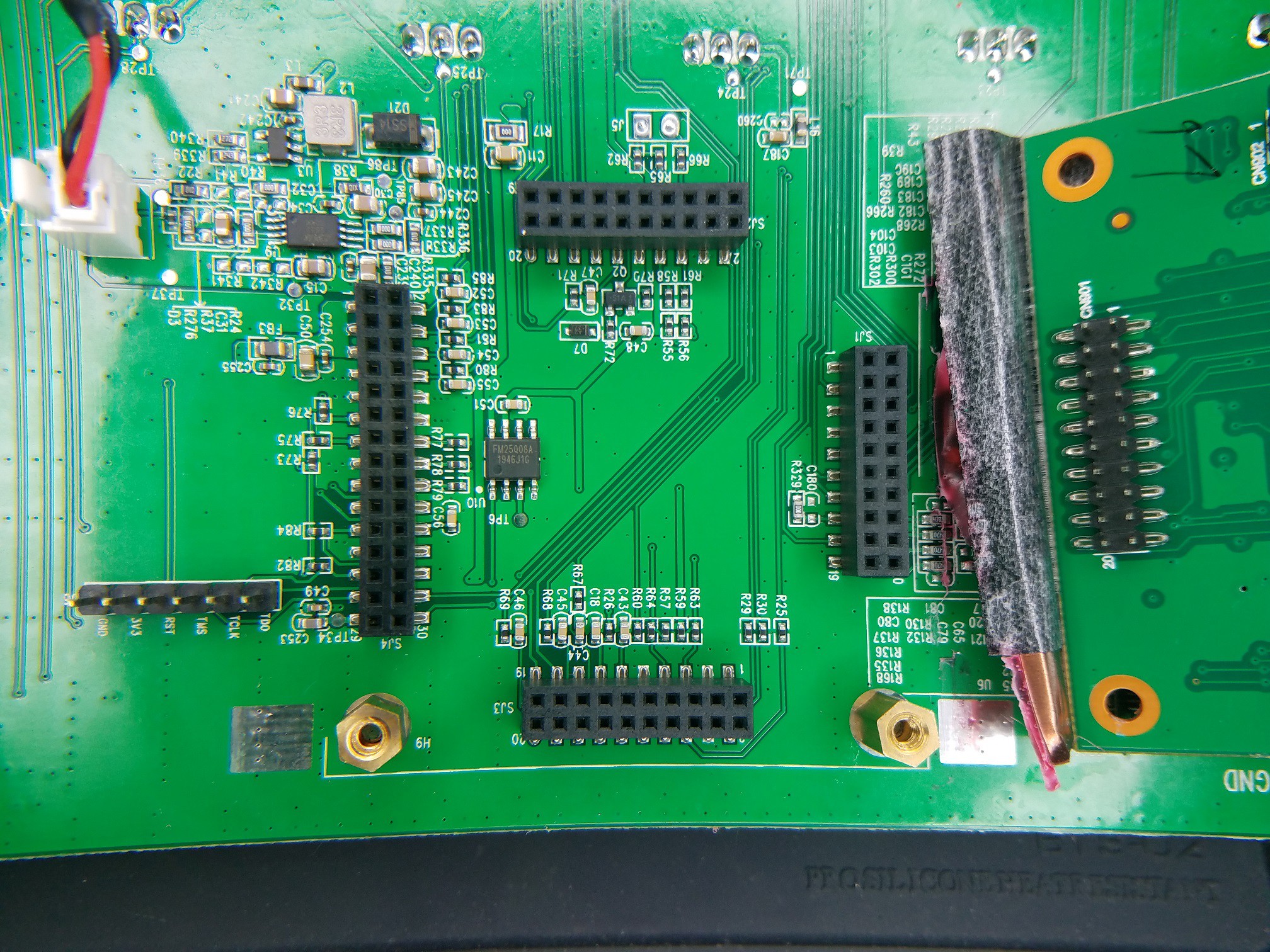
Underneath the processor module on the main board is not much at all, some passive components, and one IC, the FM25Q08A 'Serial 8Mbit (1MB) Flash'. Not sure what exactly they are storing in here... maybe the 4 profiles on the amp, not entirely sure....
You can actually use the processor's 'flash program area' to also store things that the program can use (ie like the profiles), but you also have to be careful to not overwrite this when updating the firmware itself.So they may have found it easier to just hang a serial flash off of one of the SPI/I2c interfaces on this chip, as the STM32 family has plenty of these.
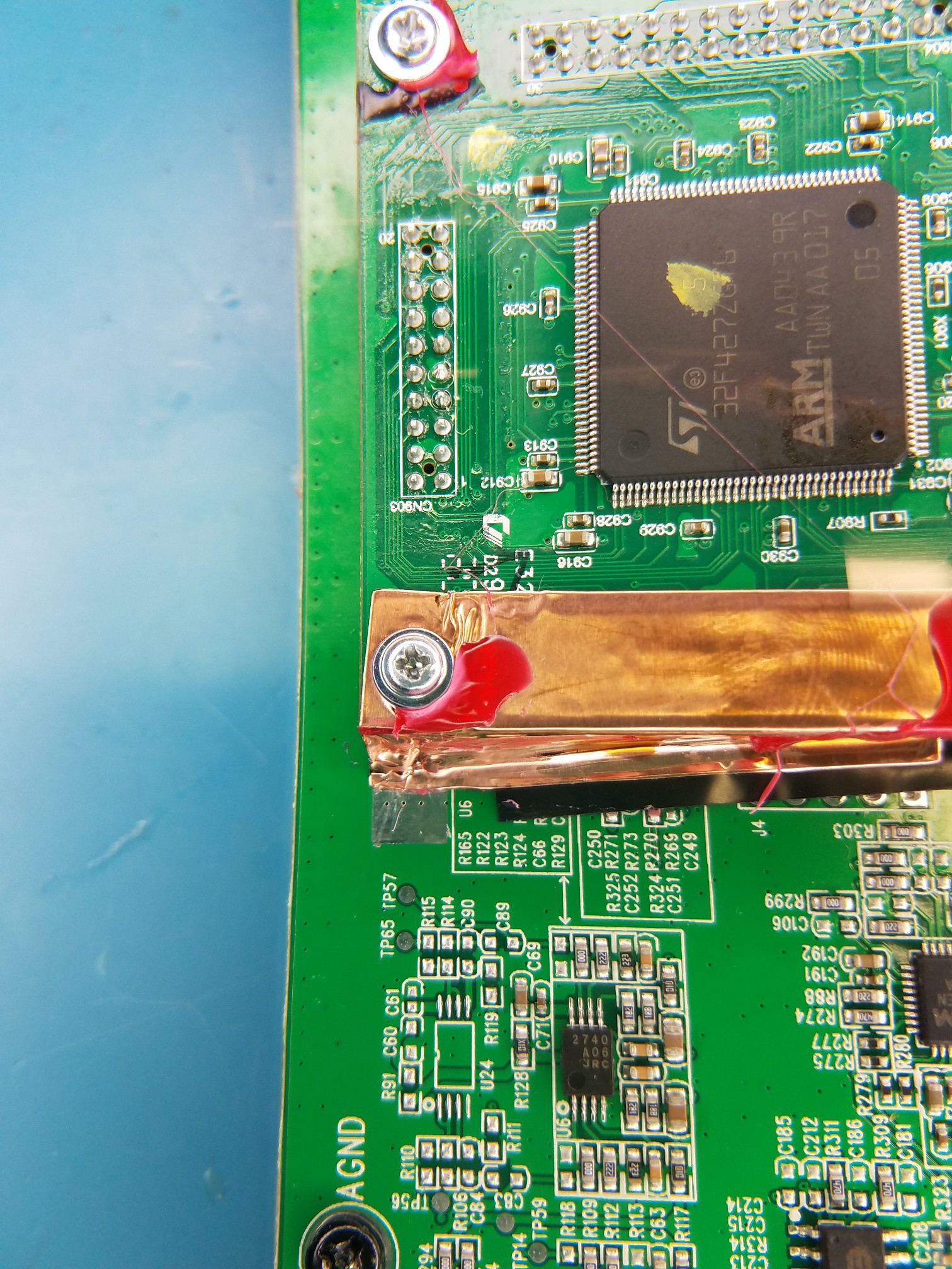
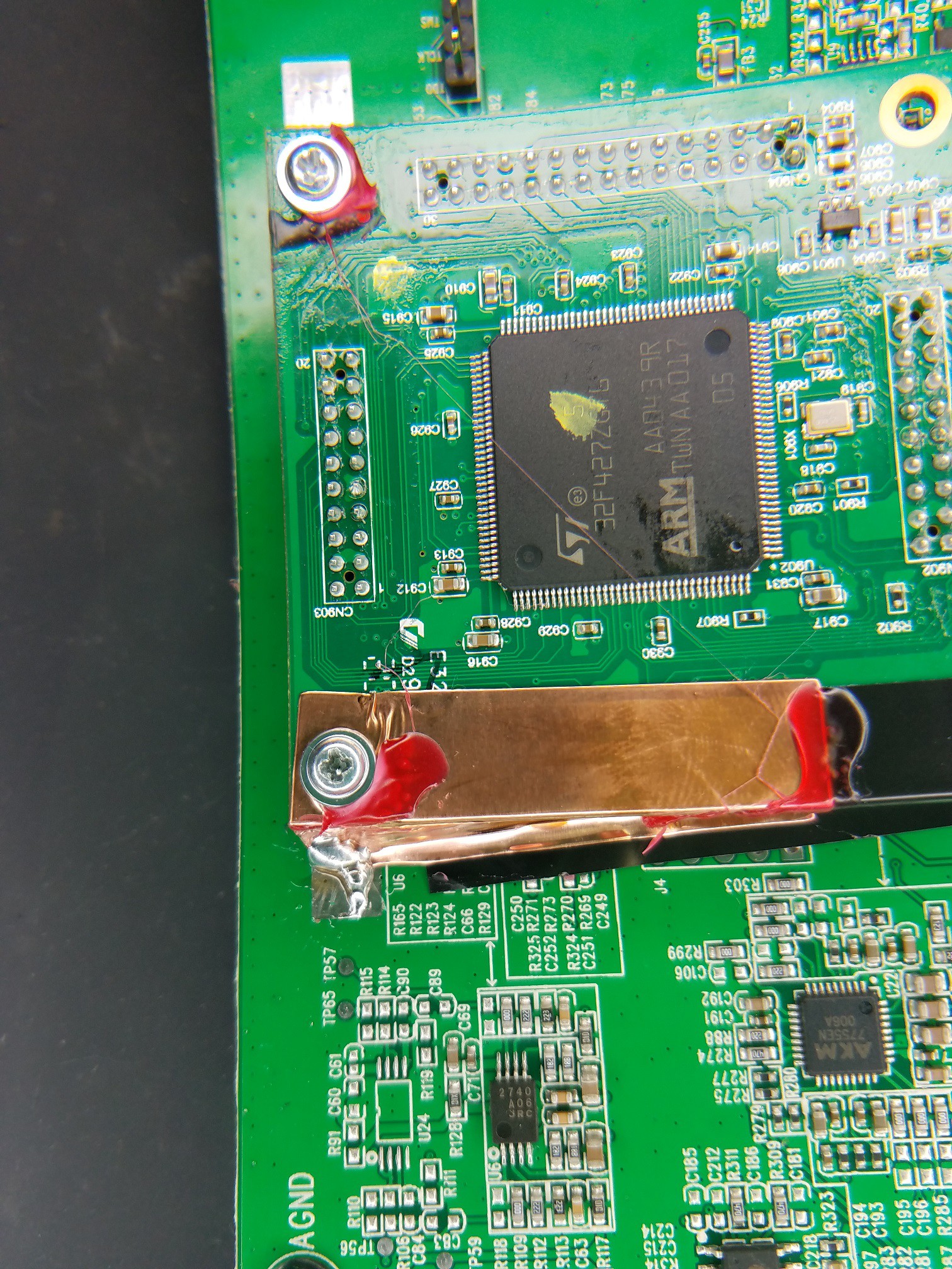
The processor module also has an interesting piece of copper strip, looks like they wanted to use it as some extra grounding between the processor module and the main PCB? But I'm sure they added GND pins through the headers, so not sure why they added this... Also it wasn't really connected to the GND pad that it was touching, only through some contact glue..
But I added some actual solder between them to make a real connection :)![]()
![]()
![]()
![]()
![]()
-
SPEAKERS - 4 OHM
08/05/2020 at 18:02 • 1 commentThe two woofer/driver speakers are one-way speakers (ie no mids or tweets), which is pretty much the usual with a guitar amp anyhow, since the lows to mids are the usual frequences we worry about in the guitar amp world.
But... considering this IS also a 'bluetooth' speaker you can play your own music on, would be nice to add a couple two-way coaxial speakers, commonly found in the car-audio realm.... I honestly don't know if they are passing the full freq. spectrum to the AMP section anyhow, they may have a low-pass filter setup somewhere along the circuit to cut all mids and highs out...
The amp is stereo (2x 50W), so each 4 Ohm speaker is connected to one channel of the 2 channel amp. My guess is that these speakers are rated at 40W, which is why it appears the TPA31162 amp chip (PLIMIT pin 6) is setup with a value, to limit the max output power. (ie 40W max versus 50W full power of this chip).
*** UPDATE: ****
I did check out the PLIMIT SETUP, there is NO resistor divider setup, they had the footprints there if they wanted to drop the output power, but currently PLIMIT is tied directly to GVDD, so indeed this AMP is setup as full power, 50W x 2.
*******************
So really we will just have to test it out unless we can identify filters on the PCB....
The 'cutout' holes are 3.75" diameter, and the mounting area for the speaker 'flange' is around 4 1/8", a little more in the areas where the corners/screw holes are because of the odd shaped mounting flange.
Shouldn't be too hard to find some car audio 2-way coaxials that have a 3.75" (or smaller) cutout size, as long as the mounting area is larger than the 3.75" hole so we can mount them!
![]()
-
USB 2.0 SECTION
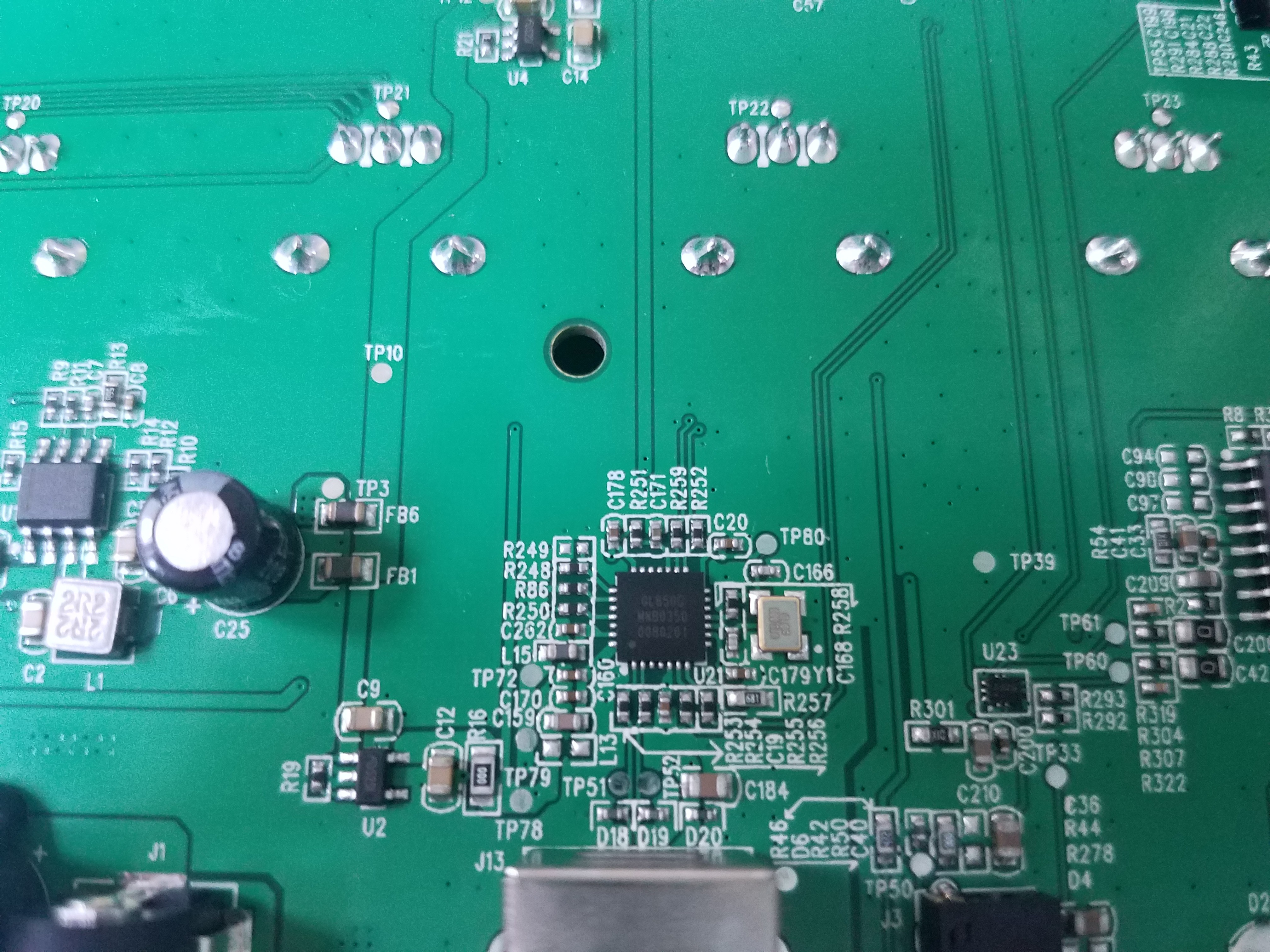
08/05/2020 at 16:46 • 0 commentsThe picture below shows the USB section of the pcb, nothing too exciting, a standard USB interface IC...
(GL805G)![]()
-
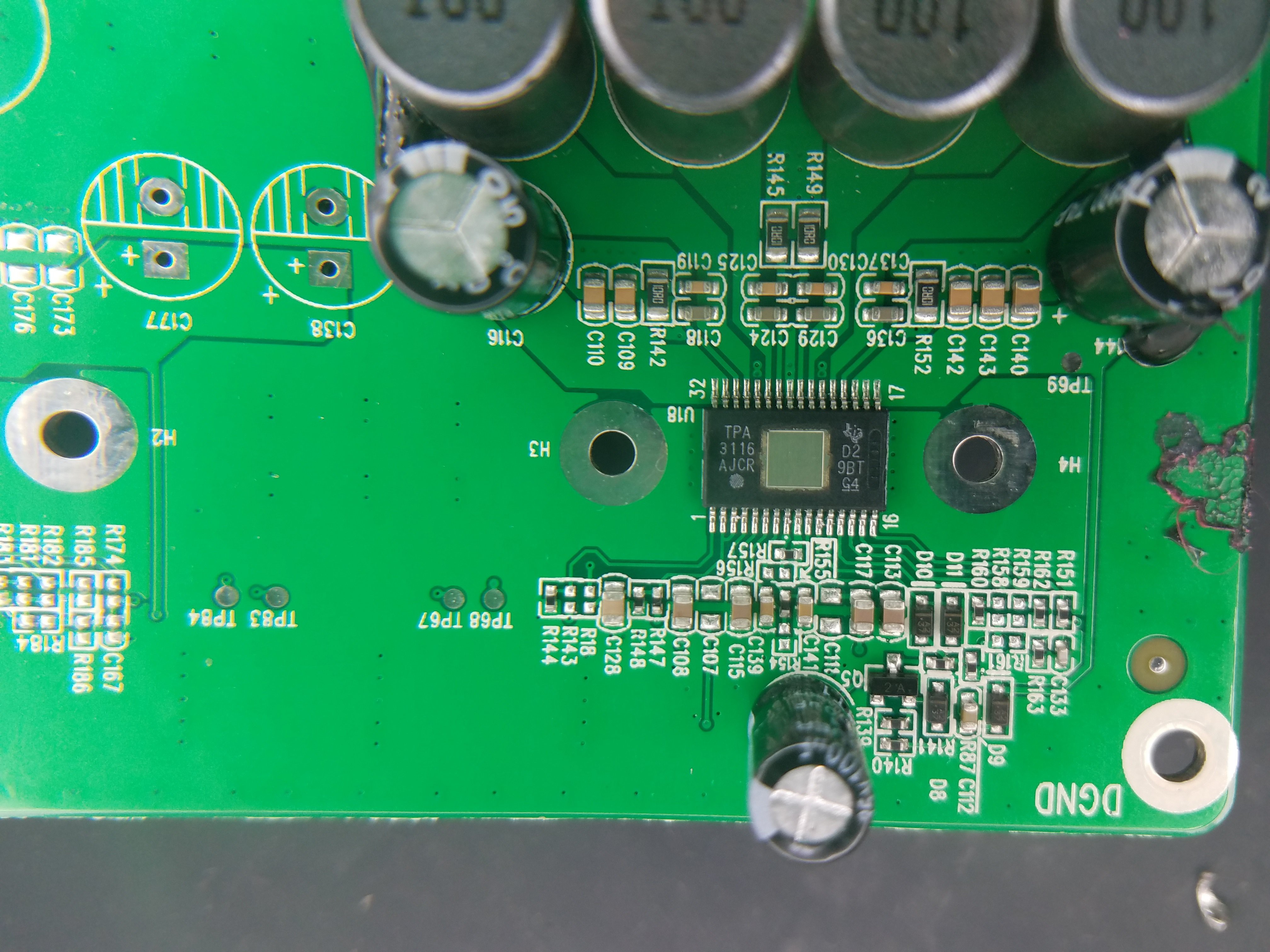
CLASS-D AMP SECTION
08/05/2020 at 16:40 • 0 commentsBelow is a close up of the Class-D amplifier section, which uses the TPA3116D2 50W x 2 (Stereo) amplifier IC. The heatsink and heatsink compound has been cleaned off to show the pinout and associated components.
(https://www.ti.com/product/TPA3116D2)
I've been looking at the input audio signals on my scope, and I'm starting to get suspicious that the input gain range is too low, which would explain why the volume doesn't get very loud. Normally a 2x50W system at full volume can get really loud. This thing at full volume almost sounds like a 2x20W radio.
I'll probably at some point post up a partial schematic of the DSP, OpAmps, to TPA3116 connectivity, to show how the DSP outputs through the op-amps and out to AMP.....
![]()
-
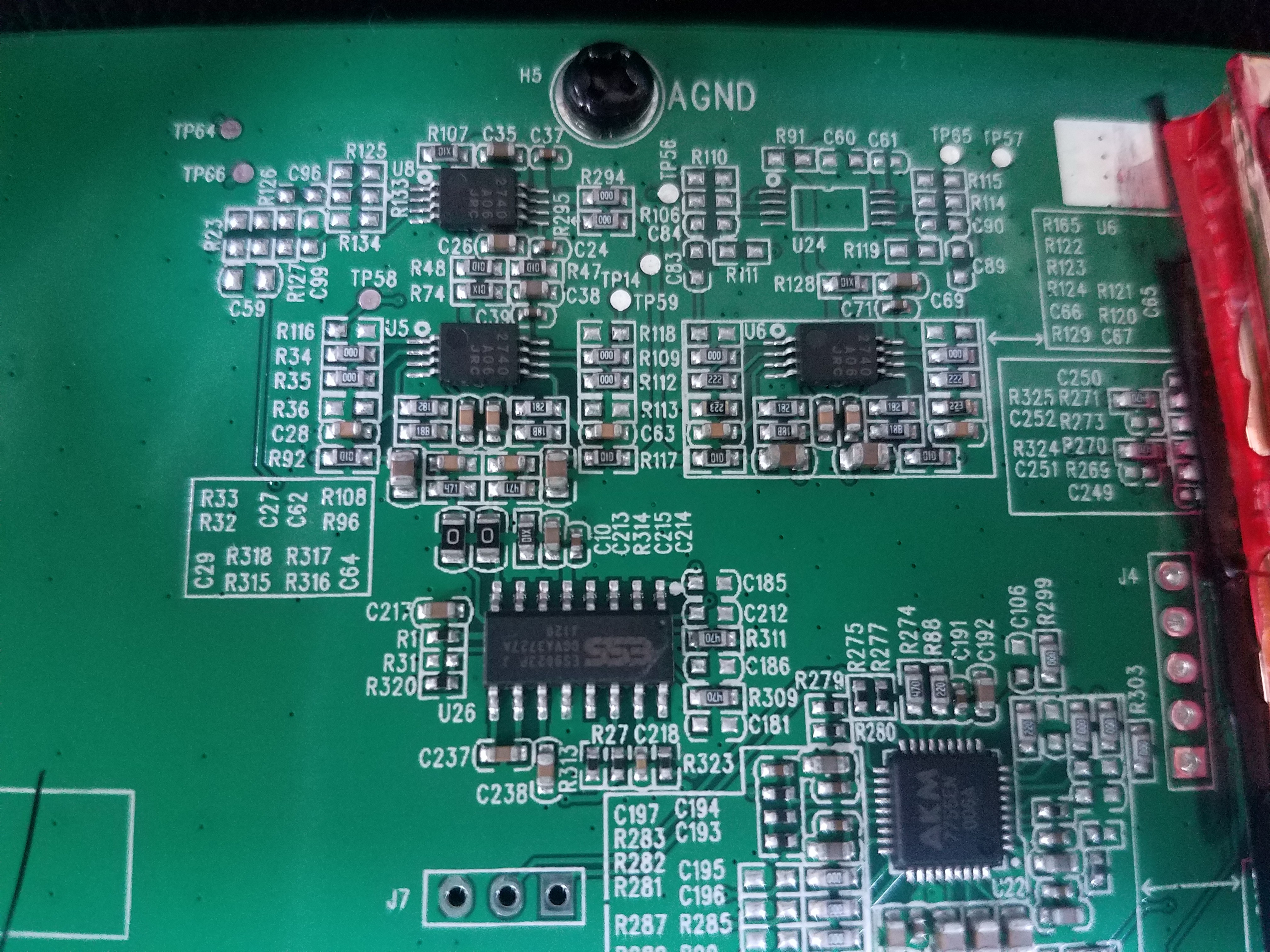
DSP SECTION
08/05/2020 at 16:33 • 0 commentsBelow is the close-up of the DSP and related section, showing the three NJM2740 op-amps, around the ES9023 Stereo DAC, and the AK7755 DSP.
![]()
-
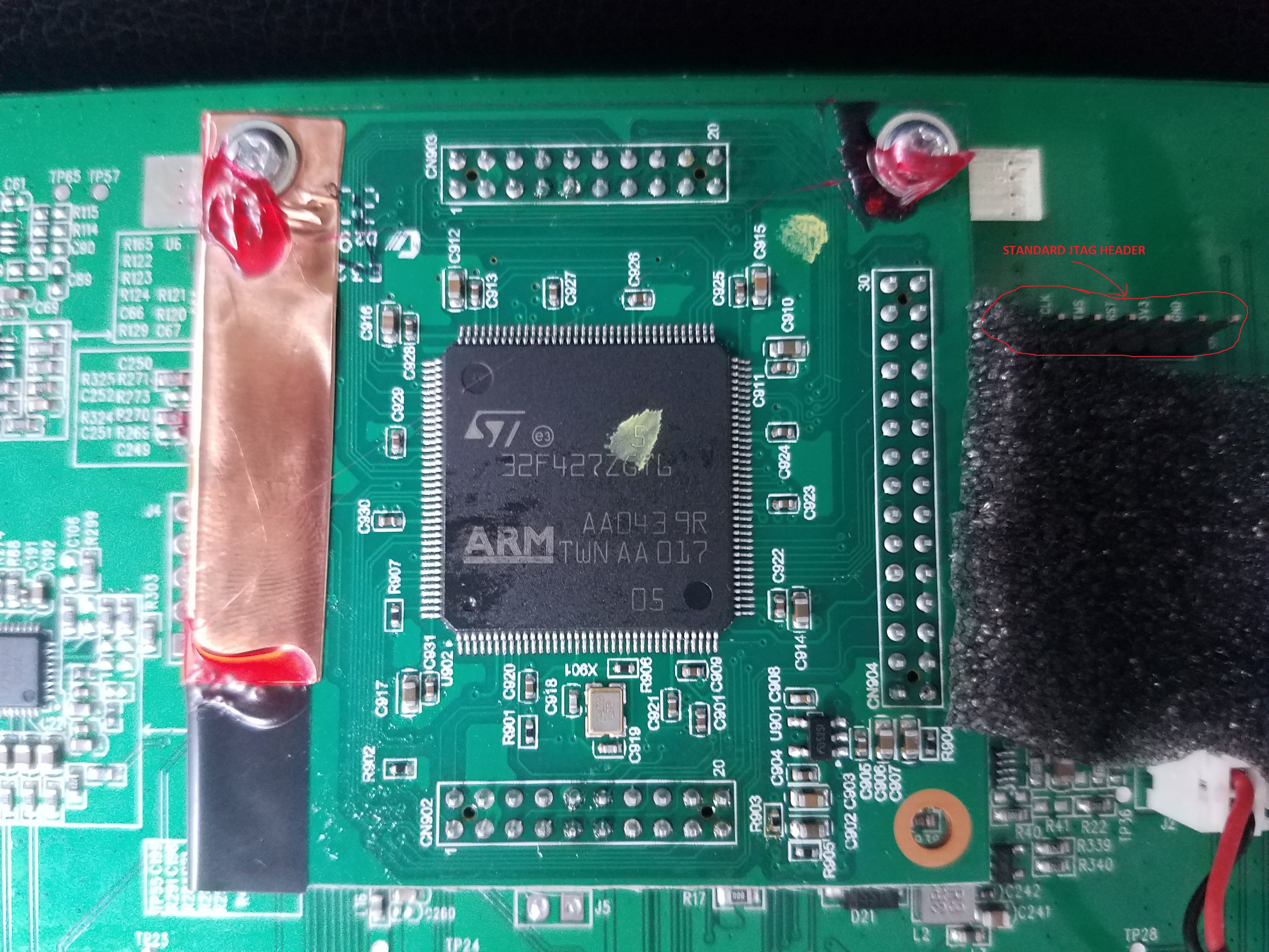
JTAG HEADER
08/05/2020 at 16:30 • 0 comments![]()
The main PCB has a populated JTAG header, for standard 5-pin JTAG debug and flashing of the firmware.
I did not test out the header to see if the STM32F4 has the 'ROP' (read-out protection) enabled or not. This is a feature on most of the STM32 family. You can set 'level's of the ROP protection, protecting the flash contents of the chip from being read from the debug interface.
Positive Grid - Spark 40 Teardown/Mods
This project is to document the teardown of the Positive Grid Spark 40 Amp, the internal components, and any cool mods!