Close
0%
0%

Simple 16-bit Computer

Simplified 16-bit computer using mostly 74LSxx logic

Similar projects worth following
Custom designed 16-bit computer with 128KB of memory (64K words) . Uses a modular design with a central bus, allowing for future extensions. The aim is to implement a full CPU with custom hardware, micro-instructions and compiler. Programs can be run from program cartridges for Harvard (or von Neumann using a program loader in EEPROM) architecture.

This has been an ongoing project for over a year before being added here, so in addition to the overall design here, I will merge everything done so far into a the first log rather than trying to separate everything as it happened.

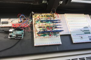
Several years ago, there was a number of very interesting tutorial on making an 8-bit computer in breadboards produced by Ben Eater. While I had done some electronics before (mostly for school), this was my first large scale project which. With the help of these tutorials I was able to build it myself:
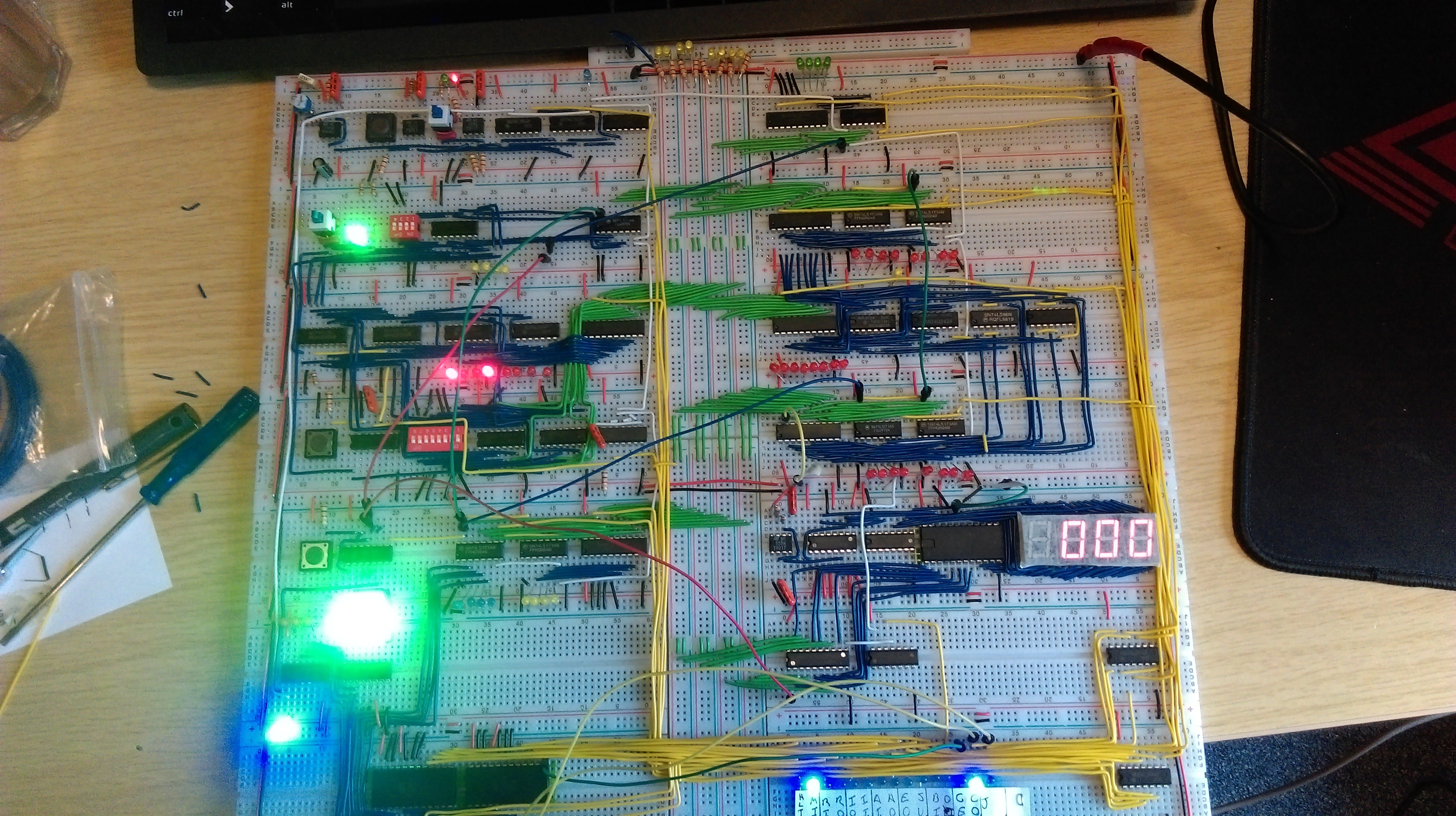
This computer uses 74LSxx chips for almost everything, with the exception being 555 timers for clocks, and AT28C16 EEPROMs as configurable logic to prevent some parts getting way to large. While I could get it running, it only has 16 bytes of memory, and to program it you need to set each byte individually. This firstly isn't much memory to do anything in, and secondly doesn't scale well even with an expanded memory. It also wasn't exactly my project as I had just followed a tutorial. As such I decided to build my own better, bigger, and as it turns out very troublesome version. There where several design considerations I set as rules:

  • The computer would use a 16-bit word
  • The computer would mostly use 74LSxx chips
  • I was allowed to use more complicated chips for RAM and again use EEPROMs for configurable logic where size would get out of hand
  • Use PCBs rather than breadboards to make it a bit more permanent
  • Be able to store a program in EEPROM chips rather than enter it manually
  • Have as much RAM as is feasible for the word size (64K words)
  • Be able to add new modules for future expansion
  • Keep the same rough design as the Ben Eater computer
  • LEDs, lots of LEDs

The computer has this overall design:
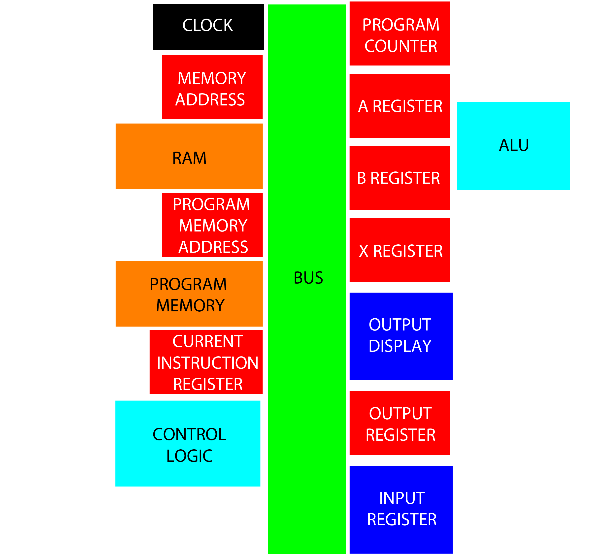
  • Clock: Synchronize the computer with both variable frequency free run and single step modes
  • Program Counter (PC): Stores the address of the current instruction
  • Memory Address (MAR): Stores the address of the value to fetch from RAM
  • RAM: Stores all variable data during runtime
  • A Register: Stores the current working value, and result from ALU
  • B Register: Stores secondary value for ALU to perform calculation
  • ALU: Performs some calculations using A and B registers, must at least to addition and subtraction
  • X Register: Index register which can be incremented using a single instruction without affecting A register
  • Program Memory Address (PMAR): Stores the address of the value to fetch from program memory
  • Program Memory: Stores the program in EEPROM
  • Output Register: Stores a value to be displayed
  • Output Display: Displays  16-bit value as decimal
  • Input Register: Allows user input of some form, should allow for both wait for input and read current value
  • Current Instruction Register (IR): Stores the current instruction being used, must be 16 bits plus the opcode size (likely just use 2 word register)
  • Control Logic: Decodes what is in IR to generate control signals for the rest of the computer, also handles flags and reset

ToDo: Write about choice of RAM and EEPROM, and some other design stuff (either here of in log)

With everything designed the full computer looks like this:
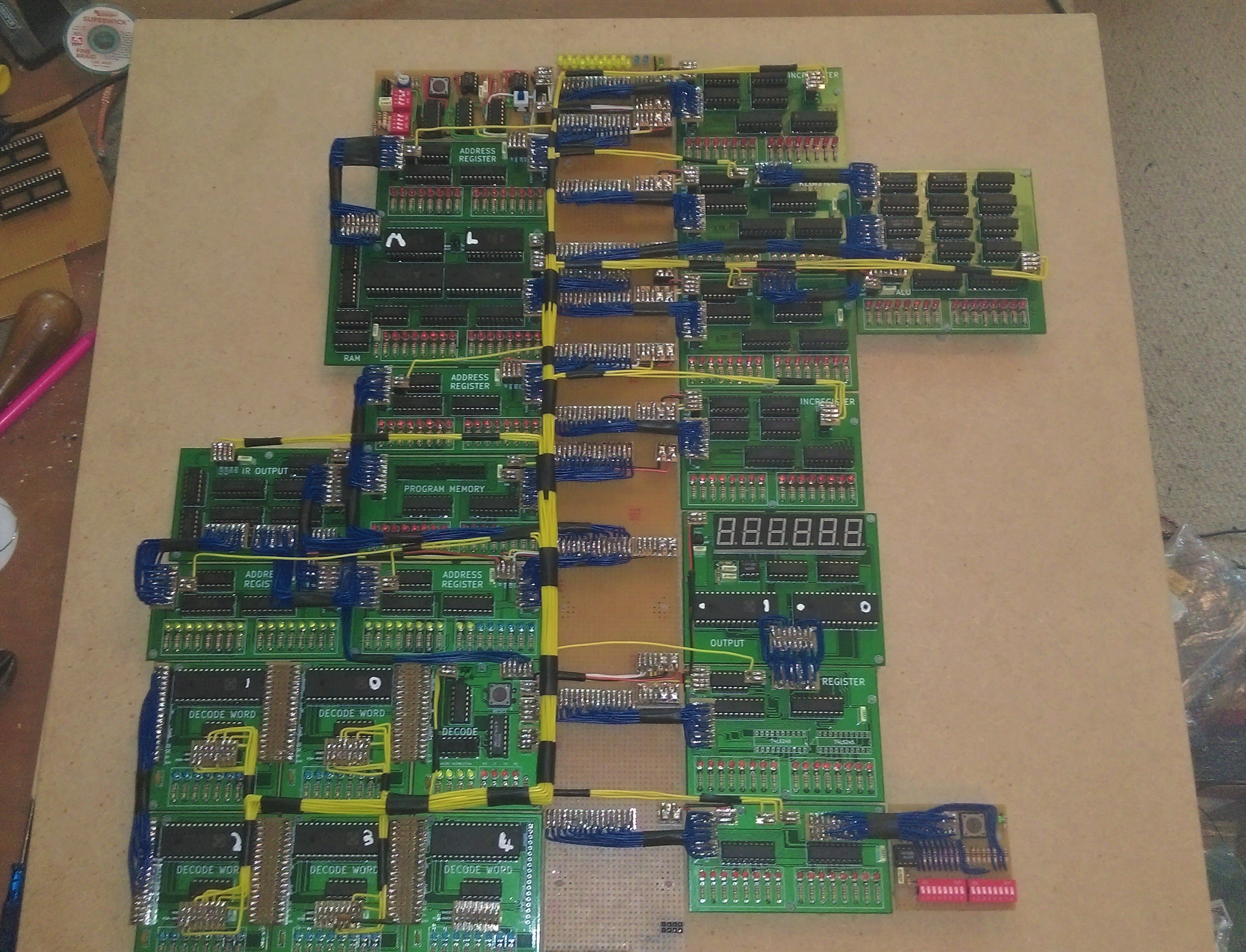
Unfortunately the computer isn't fully functioning. All separate modules have been tested, however the complete thing does not operate correctly. There are several problems to solve:

  • Clock does not have a fast enough slew rate to function with 74LSxx logic.
    • This has temporarily been replaced with the clock from the original Ben Eater computer.
  • Control logic EEPROM 4 outputs high on each bit, regardless of being programed (and checked) to be all 0x00. This isn't really a problem as it is an extension to the control word and non of the bits are being used.
  • Rough control signals are being generated. This causes modules to not perform correctly, mostly reading values whenever another register reads. THIS IS THE MAIN PROBLEM TO DEAL WITH
    • It seems adding a 10nF capacitor to ground on the control lines somewhat helps with some modules. This has not been tested for all affected control lines,...
Read more »

Factorial.asm

The assembly code for a simple factorial program, using an emulated stack.

plain - 3.36 kB - 10/14/2020 at 23:20

Download

Microcode.cs

This generates the control word for each instruction based on what flags are set, and what the current micro-instruction is. This can be used to generate the data for the EEPROM of each control byte.

plain - 16.88 kB - 08/10/2020 at 00:27

Download

Instructions.csv

The compiler data for each instruction available to the computer

ms-excel - 6.00 kB - 08/10/2020 at 00:26

Download

  • Programing

    Charlie Smith10/14/2020 at 22:49 2 comments

    Since the last log I have got the program card to be fully working, so the only incomplete parts to the computer are the input module and the clock. The input module still isn't a priority, and I will talk more about the clock below. I am now able to easily program the computer using my EEPROM programmer and a program card. So I can now start looking at areas to improve, as well as writing more complex programs.

    The Stack

    This is pretty much my first time using an assembly language properly, so while I could attempt to write some super complex program, it would be better to understand a bit more about how to write programs. Well there is a clear feature I should look into: the stack. The general idea is that we can store values in memory without having to allocate a variable in advanced. By using a stack data structure, we can either push a value onto the stack, or pop a value of the top (you can also peek to look at the top value without removing it). This is often compared to a tall pile of plates. You can either add one to the top or remove one from the top, you can't remove one from the middle (without being very careful). The implementation of this is fairly simple, all that is needed is a large region of memory that isn't used for anything else, and an address pointer (stack pointer) to the top of the stack. To push a value onto the stack we can increment the stack pointer and then place the value in memory at this new address. To pop a value from the stack we can read the value at the current stack pointer, and then decrement the pointer. As this tends to be used a lot, the stack pointer is often implemented at a hardware level, although this isn't required.

    While, we have no dedicated hardware module for a stack pointer, it isn't too difficult to come up with an emulated stack pointer. This can be done by having a global variable in memory for the stack pointer itself. This pointer can go anywhere in memory, but will need to be set to some where the stack should be in memory when the program starts. 

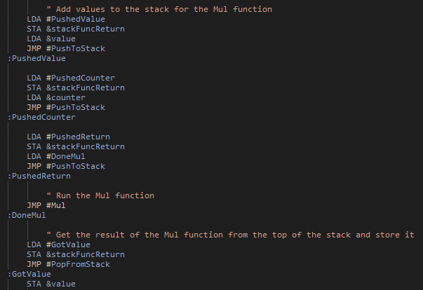
    We next need to consider how the Push, Pop and Peek functions should be called. Clearly this can't be done in the same way that normal functions are done, as they will use the stack. So for this the general idea is that the function either puts or uses a value in register A, and then jumps the code back to where we where just running. I don't really think there is much use right now of having a dynamic method of getting the current instruction address as a piece of data, so instead we will just set another global variable to where we should jump back too using a label. This example then shows the rough way that a function is used. For each argument (and return location) the value is loaded into register A, the location to return from the stack function is set and then we jump to that stack function. We can then go to that function, which will need to pop the values from the stack, before putting the result back onto the stack. Finally we can pop that value and save it to memory.

    With that in place we can start building more complex programs, making use of functions. For this first example I've defines a multiply function, taking two values from the stack, and putting the result back onto the stack. I think this should actually put the return location onto the stack before the arguments, so as to make calling multiple function calls easier. Anyway, with this function we can now do some more interesting tasks. For example, we can compute factorial numbers up to the maximum we can store (1, 2, 6, 24, 120, 720, 5040, 40320). It will be interesting to implement 32 or 64 bit numbers in the future to allow for larger values, although then we will also need a better method for displaying a number. It did take me a few attempts to get this program (Factorial.asm) working, but was extremely satisfying when it did:

    I should note that to get the program working, I was making use of a simulated version of my computer...

    Read more »

  • It Actually Works (Mostly)

    Charlie Smith09/22/2020 at 02:02 0 comments

    This project has been was sort of put on hold again shortly after the last log. While at the time I had made significant progress to getting it working (it could run most unconditional instructions), it promptly stopped working again. I also had only been working on it while I was unable to work on another project as I was waiting on something to arrive, so when I could continue with that this was put back on hold. However, as I decided to take a short break with that other project I decided to have another look at this one. 

    Additionally thank you for the comments, and sorry for not replying till now. Firstly for the clock I will probably use a Schmitt trigger to buffer the signal, but currently I don't have any so will stick to the 555 timer which does the job for now. Secondly, I'm not sure if there is a race condition, control bits should be set out of phase with the clock being active. But even after the fixes I will talk about shortly, I very much still need to use capacitors on the control lines to slow the signals down. Possibly the GLS29EE010 EEPROMS can't drive chips that far away in addition to an LED, and need a buffered output (dimming the LED may also help, and probably should be done anyway). For all data LEDs in modules, they are actually buffered using 74LS245 octal bus transceivers, so while it probably doesn't affect the ability for data to be moved around, it does result in quite a large current draw (especially when lots of modules have data). Finally, yes simple probably isn't the best term to use. But in comparison with even fairly simple microcontrollers or existing CPUs, it is relatively simple. At the very least I can built it and not worry too much about some aspects of the design.


    So lets start looking at some of the problems the computer had. The first issue was that the output control bits for the current instruction register (CIR) where done incorrectly. This is mostly due to some unnecessary complication I added to allow for some extra functionality which is probably not going to be used. The CIR is a two word register where the 6 least significant bits give the OPCODE of the current instruction, while the remaining 26 bits give the OPERAND. This is needed because with only a single word, only a 10 bit OPERAND would be available and so only 1K words over RAM. Because I wanted the full 64K words available I need to allow instructions to make use of two words when the OPERAND is a memory address. This mean I need to be able to output a 16 bit value to the bus. However, if the OPERAND is a number less than 1024, then only a single word is needed and I only need to output a 10 bit value to the bus. Finally the overcomplication: With 26 bits of OPERAND available, I can allow for instructions to use two 13 bit arguments as an OPERAND. This lets me make full use of the two word CIR, but does mean that I need to allow for two 13 bit values to be outputted to the bus, one offset by an additional 13 bits. This gives 4 total output modes:

    • FAST: The last 10 bits, from the first word
    • FULL: The last 10 bits from the first word and the fist 6 bits from the second word
    • MLT_0: The last 10 bits from the first word and the first 3 bits from the second word
    • MLT_1: The last 13 bits from the second word

    However, having multiple arguments isn't all that helpful (especially with a quite limiting 6 bit OPCODE, I should have made it 8 bits). The issue is that somewhere along the line the control logic for getting these different outputs got messed up. Firstly the FAST, FULL and MLT_0 control bits where being inverted, and secondly they where not being combined correctly anyway. Luckily, I could correct the problem quite easily by replacing an 74LS32 quad OR gate with a 74LS02 quad NOR gate, and redoing a few traces:

    I also needed to un-invert the control bits. This is also quite easy, as each control word allows contains not only a GLS29EE010 EEPROM, but also a 74LS04 hex inverter....

    Read more »

  • Build Summery

    Charlie Smith08/15/2020 at 01:56 0 comments

    Again this will just be a summery of the build of the computer, to get mostly up to date with the project. Mostly of the actual work was done a little over a year ago, and unfortunately I didn't take as many pictures as I should have done at the time.


    Build Method

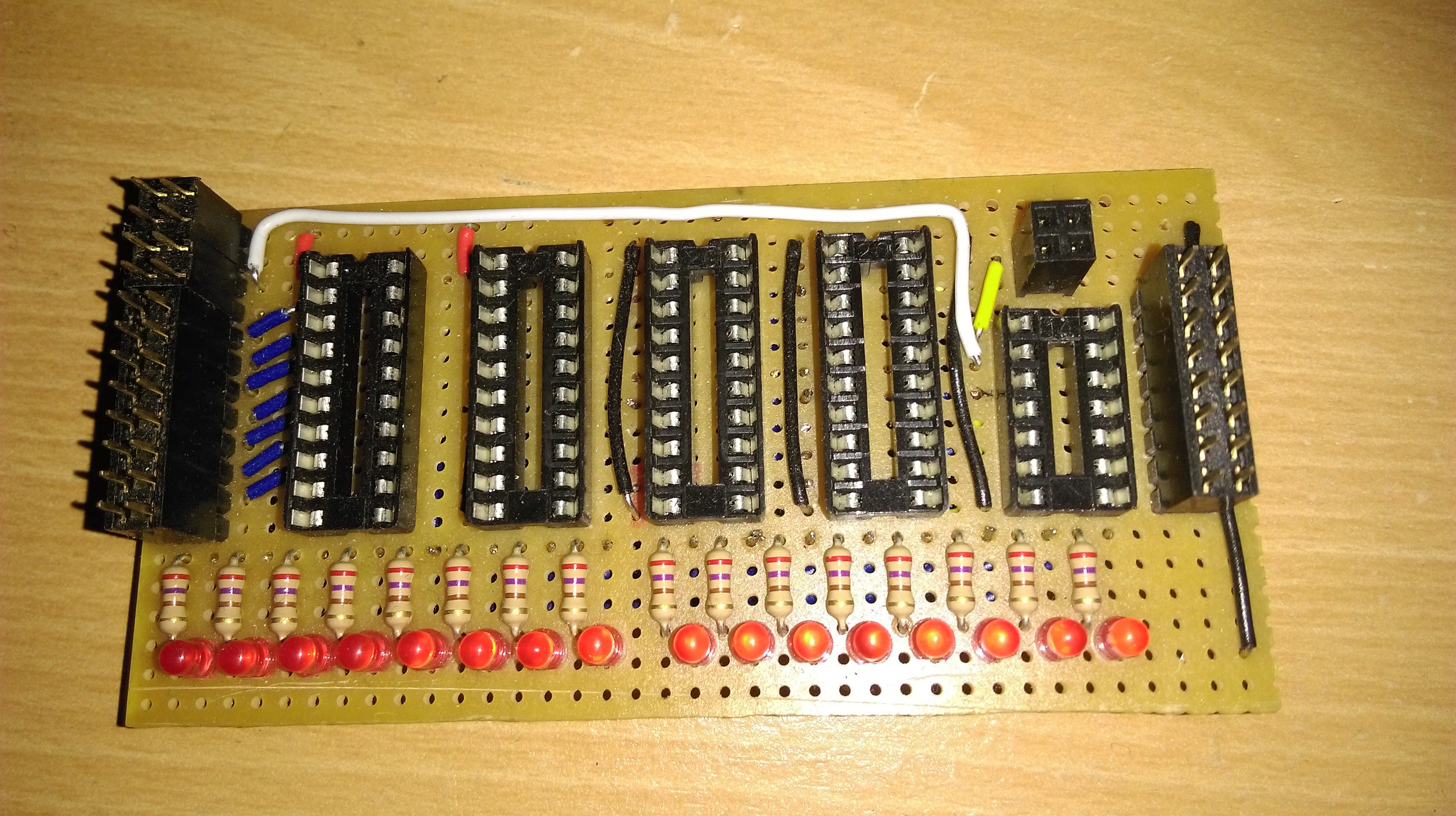
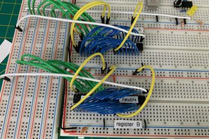
    The first decision was exactly how to build all the modules. Clearly PCBs are a really good option (and the one I used) but there are still choices over how to have them made. However, originally I planned on using strip-board. This seemed a reasonable upgrade over breadboards, and so I started experimenting with building a register. That resulted in this:


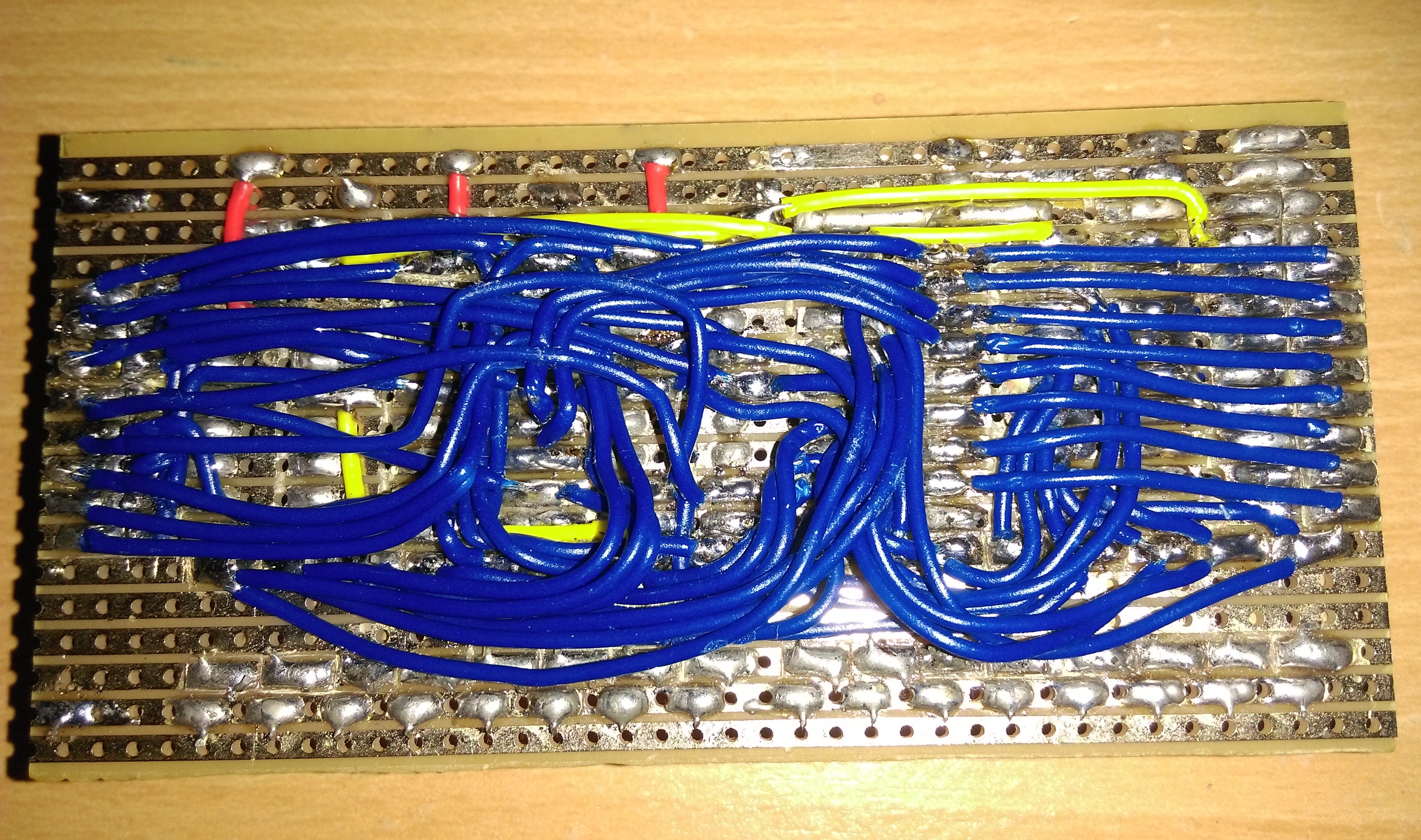
    While this looks rather promising and allows for fixes and modifications when needed, there is the slight problem of the other side:This is clearly a mess (and I'm surprised that I did so much of it before giving up). It was very tedious to build, prone to error, and extremely difficult to debug and fix. The main issue being that with 16 data lines (needing a connection from the bus connection to the flip-flops, from the flip flops to the LEDs, from the flip-flops to the bus driver, and finally from the bus driver to the bus connection), and the remaining signal and power wired: over 70 individual wires are needed, and this is one of the simpler modules. As such I gave up building the entire system in this way. There are still some parts I still decided to used strip-board. Most notably the bus as it is so large, and mostly just a lot of parallel strips (i.e. exactly what a strip-board is). As an alternative fabrication method I had an experiment with making my own PCBs. For this I tested an EEPROM programmer for the AT28C16 ICs. For this I set up a headed container of Sodium Persulfate (as its apparently cleaner and more controllable than ferric chloride) with an air bubbler. To place a mask for the copper to keep, I experimented with laser printing onto paper, placing the paper toner side down onto copper clad board, heating the lot with an iron, and then removing the paper after soaking it in water for some time (there are definitely better tutorials out there that explain this). After a couple of attempts at transferring the mask I ended up with one I was happy with, etched and added the components:
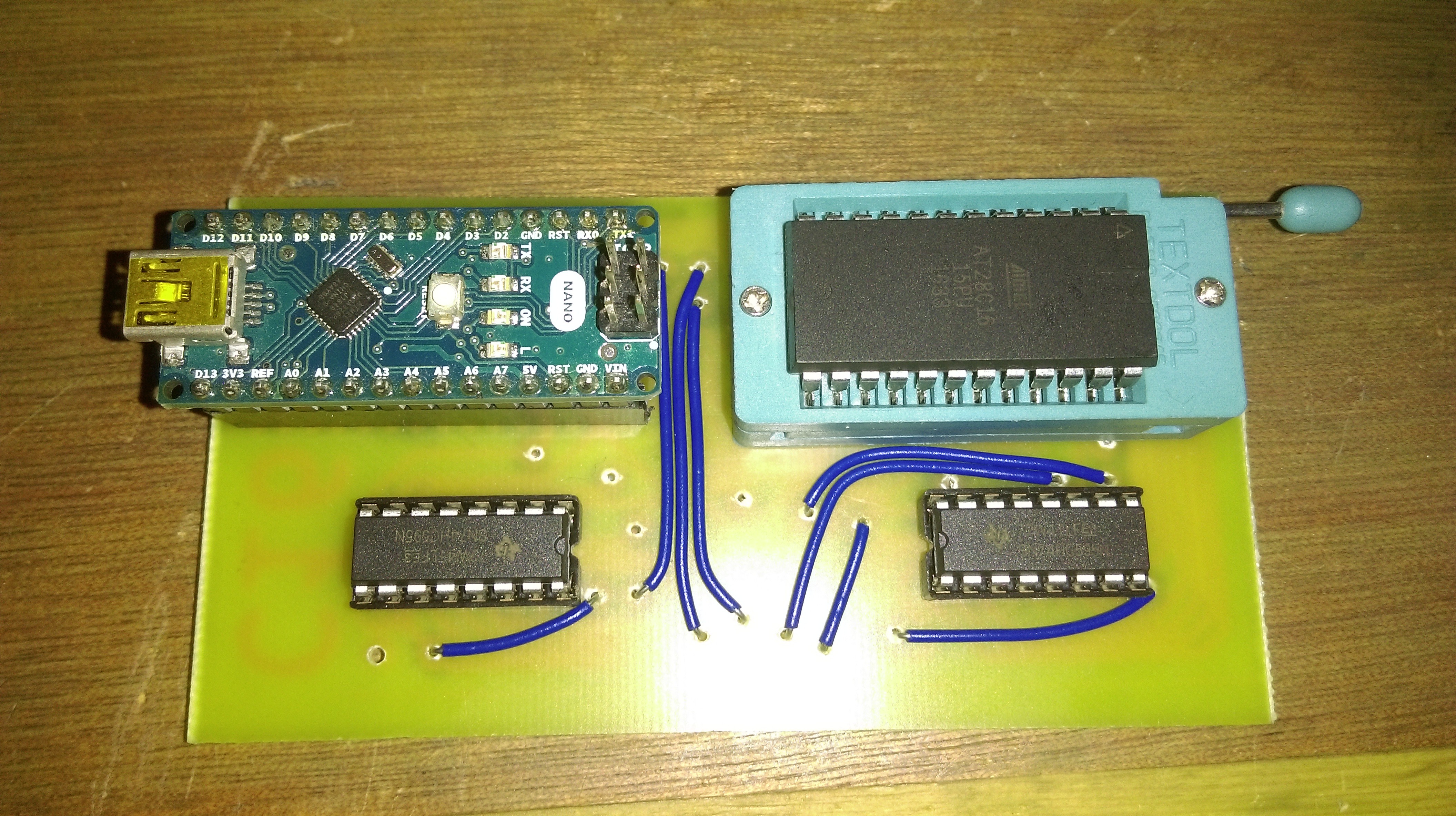
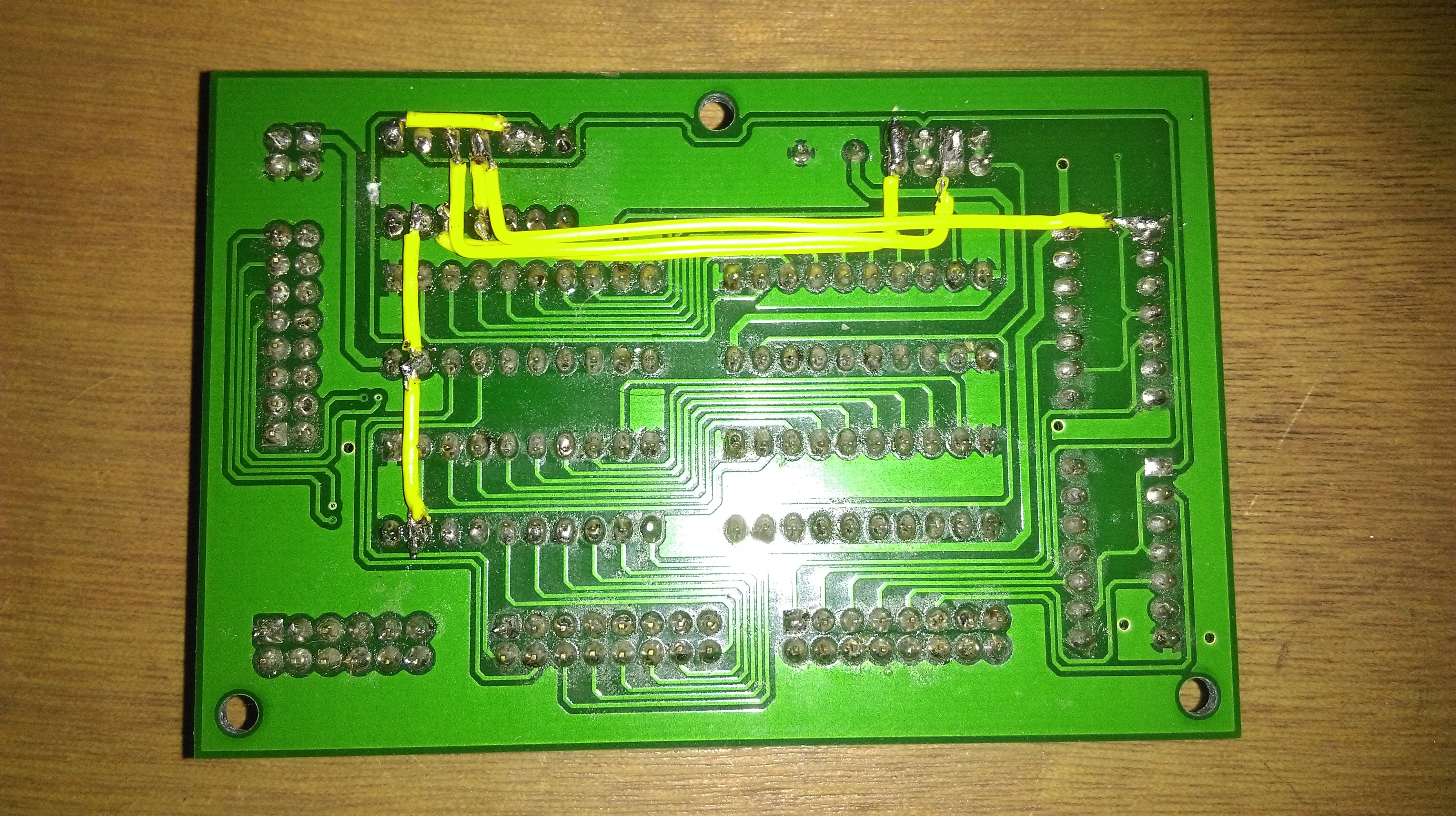
    This needed a few extra wires as it is a single sided board (double sided like this sounds difficult), but this needs far fewer than on the strip-board. The other side:
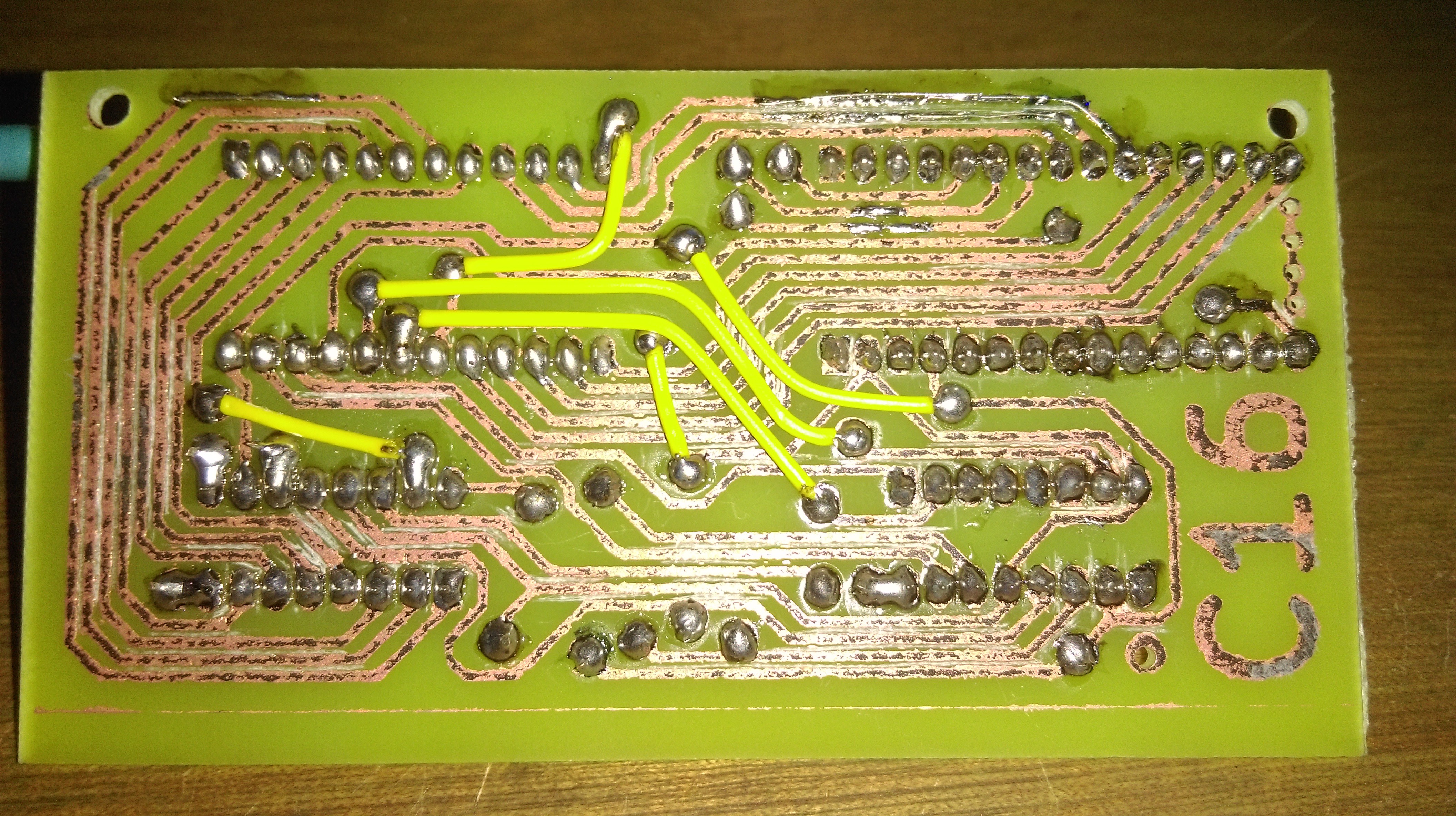
    Amazingly this worked with only a few traces needing to be fixed (some extra solder on traces at the top of the picture). There were a few issues with the process of making this. Firstly transferring the mask wasn't very reliable, perhaps I need to consider printing on thinner paper to stop the toner being pulled off when the paper is removed. Secondly, etching was rather inconsistent with the bubbler I used. The bubbler only really did anything directly above it, this can probably be fixed by using one that bubbles in a line, rather than from a point. Finally, and most importantly, the board stopped working shortly after it was made. This is likely due to damage to one of the traces from the lack of solder mask. Overall the process was somewhat successful, but probably a bit too unpredictable for what I want. What's more, I then discovered JLCPCB as an extremely cheap way to get two layer boards manufactured properly. I even got free 3ish day shipping with a test order I made (so I spent an entire £1.53 to get 5 test register PCBs). These tests looked very good, and let me use two layer PCBs so I ordered a full set of boards (unfortunately I had to pay shipping this time) along with all the ICs I expected I should need.

    Modules

    To build the computer I started with a roughly 560mm x 560mm x 6mm sheet of MDF. I then sketched out in pencil some construction lines before adding mounting points which the PCBs can clip onto. These have an M3 bolt going through the MDF into the post , so require some fairly well placed holes, based on each PCB. To make sure...

    Read more »

  • Initial Design Summary

    Charlie Smith08/10/2020 at 00:22 0 comments

    Because this project has been going for a while (started about 20 months ago as of writing this), I will make a summary of the progress made up to to when I created the project here.

    The general idea of the computer is the same as the one designed by Ben Eater. However, I want to make a computer which firstly I have designed, and secondly is capable of running something interesting. As such, the general design will be the same. However, the computer will be 16-bit and have some redesigned modules.

    Before this project I had done some electronics projects, but basically only for GSCE electronic at school. This was my first large scale unguided project, and also my first with properly build PCBs. So take that as a warning that there are going to be some stupid choices made in the design.


    DESIGN

    Firstly, I needed to pick the modules to include in the initial design of the computer (with the idea that mode would be added later). Clearly there are some that are required for the computer to function which I will call core modules while others add additional abilities to the computer which I will call function modules. Also all modules should have LEDs to display the value currently stored in the module.

    CORE:

    • Clock
      • Synchronizes the computer so everything will work correctly
    • Program counter (PC)
      • Stores the memory address of the next instruction to read
    • Memory Address Register (MAR)
      • Stores the memory address which the RAM either read or write to
    • Random Access Memory (RAM)
      • Stores all the working data and instructions (instructions could be read from some other memory)
    • Current Instruction Register (IR)
      • Stores the data for the current instruction being run
      • Made of an 6-bit OPCODE and OPERAND
      • To allow access to all of RAM, this needs 6 bits for the OPCODE and 16-bits for the OPERAND. As such this can be a 2 word register.
      • With 26 bits for the OPERAND we can have several modes of outputting the OPERAND to the bus
        • FAST: 10-bit OPERAND so only the first word needs data make the operation faster to execute
        • FULL: 16-bit OPERAND so all of memory is accessible, but both words need data
        • MLT_0: First of two 13-bit OPERANDS allowing for two arguments to an instruction
        • MIL_1: Second of two 13-bit OPERANDS allowing for two arguments to an instruction
    • Control Logic
      • Decodes the OPCODE and any flags to a control word used to control all parts of the computer

    FUNCTION:

    • Arithmetic Logic Unit (ALU)
      • Performs all mathematical and logical operations using values in the A and B register
      • Initially this is limited to addition and subtraction
    • A Register
      • Stores the value currently being worked on by the ALU
    • B Register
      • Stores a modifier value which the ALU uses to act on register A
    • X Register
      • Index register, used to store a pointer to a value in an array
      • Needs to be able to increment by 1 without using the ALU
    • Output Register
      • Stores a value to be displayed in some way
      • Should also have a decimal decoder of the value stored
    • Input Register
      • Used to store a user input
    • Program Memory Address Register (PMAR)
      • Stores an address in program memory for an instruction or constant to fetch
    • Program Memory
      • EEPROM storage of write only data to store instructions and constant for a program
      • The actual storage should be easily removable such that the program being run can be changed easily
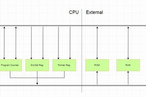
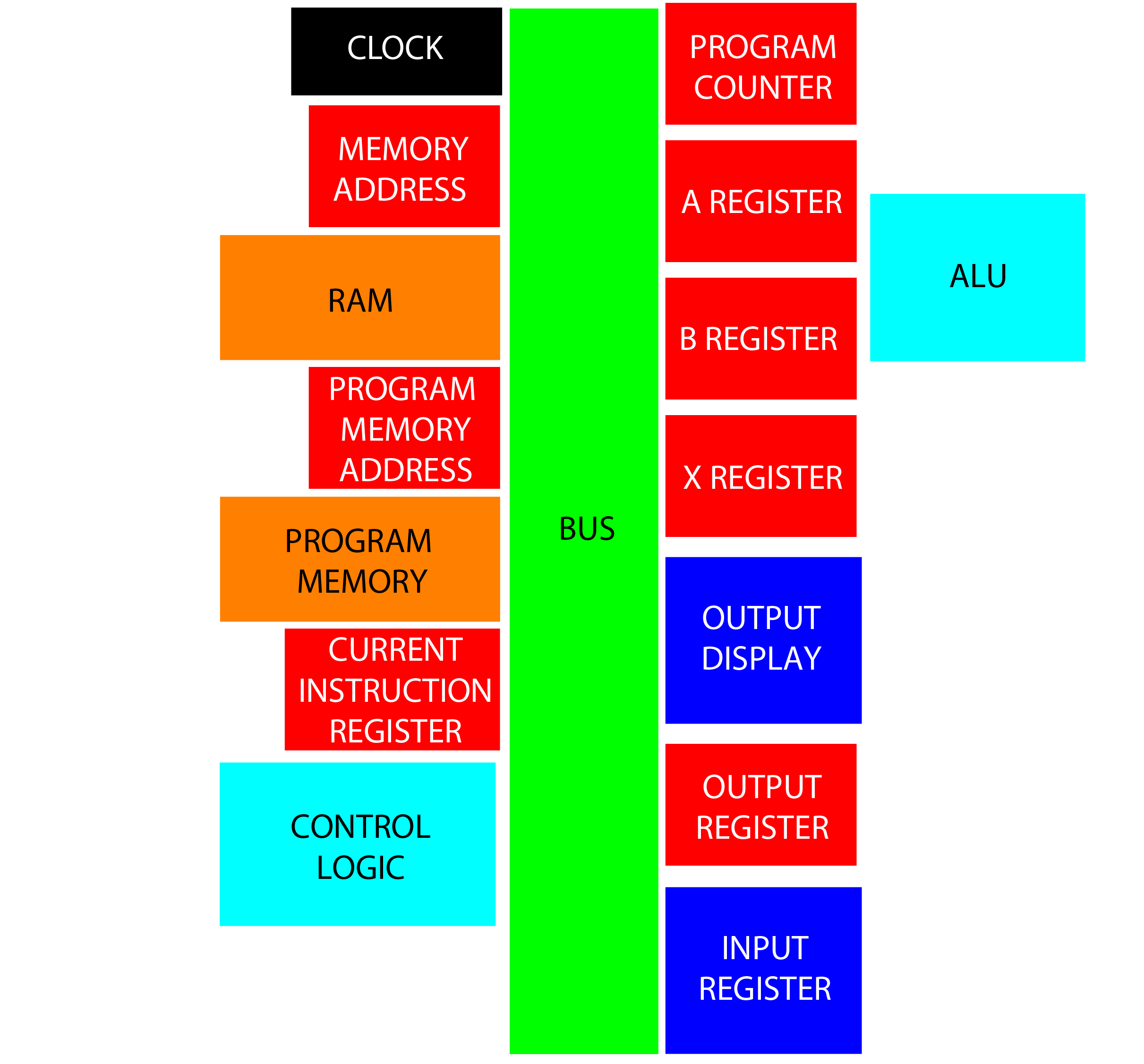
    These will all be connected with a central bus, and can have the following rough layout:

    While I could go into the design of each of these modules, this would end up being rather long. So I will summarize the main parts. Firstly a number of the modules are functionally identical, so can use the same base module, possibly with some small changes. So the A and B registers use the same hardware, while the output register is also the same, but does not need the components to output to the bus to be populated. Similarly PC and X have the same hardware, as do MAR and PMAR. The IR can also use the same parts as MAR, but will need to modules to get a 32-bit word, and also need a module to allow for each output mode to the bus. Here are a rough design...

    Read more »

View all 4 project logs

Enjoy this project?

Share

Discussions

Michael Möller wrote 08/14/2020 at 19:49 point

Thoughts and suggestions - no guarantees ;-)

"Clock does not have a fast enough slew rate" - use a schmitt trigger buffer? Especially as you mention "using a Resistor/capacitor" to decouple".

"Control logic EEPROM 4 outputs high on each bit" - sounds like somewhere you have parallel wired another output. If you disconnect the EEPROM are the lines still high (enough to llight a LED)?

"Rough control signals ... modules to not perform correctly" - You may have race conditions, ie some signal needs to arrive simultaneously with another, but one of them is transient.

"Adding a 10nF capacitor to controlines ... somewhat helps" - reinforces my racecondition suspicion. It would slow down the signal.  It also stresses the chips, as they have to supply/sink lots of current at the transition (no resistor to limit current). 

"LEDs are far too bright" - have you measured voltage? They may pull down your logic high to a few volts - still enough to be a high ... some of the time. I'd buffer them (ie use a on lines where the fanout is more than 1, or at least on the bus (I have on my project)

  Are you sure? yes | no

Mike Szczys wrote 08/14/2020 at 16:49 point

Your use of the word "simple" is different from mine. This a complex build and very exciting. Sounds like the chip selection is kind of stopped you from getting it running but I hope you'll keep hunting for a solution.

  Are you sure? yes | no

Similar Projects

Does this project spark your interest?

Become a member to follow this project and never miss any updates