-
1Step 1
Choose your design after reading as much background as you can. Prepare for ridicule from everyone you know. Have a load of loft space set aside. Avoid some of my mistakes. Don't try to fly the big ring with anything other than a rigid ring (or a swivel (if you don't want power)) on the ground. Don't make the ring out of a toy inflatable trampoline. (fun and easy but breaks easily.) Don't custom make a beautiful ply ring from local timber. Don't use a bendy pole for auto alignment... It bends not follows, use a universal joint when you (and I) eventually get there.
Keep going and get ready to have a lot of fun
-
2Step 2
Respect the hard work and dedication to a better existence given by the open source community.
Thanks must go to Grasshopper 3d algorithmic modeling language for rhino
And Thanks now in no particular order to...
David Aberdeen use of your surfplan clark-y model for Dasiy and other systems modeling
AWE yahoo forum members. Amazing feedback and analytics
SY fishermans coop having rope by the Kg
Gordon Diesels rapid development of hardware
Ivor Murrays Engineering Hardware
Leominster Kite Festival Teaching me about light wind
Rosie and Netty Sewing lessons
Murdo MacLeans having coats duet nr.30 thread by the spool
Wife, family, neighbors, kite testers, passers by for scones, scrutiny & kinship
Point North fabrics rip stop
Rhino3D developers
Evernote
Gmail it's not the only email system available
Dyneema It's not the only rope available
HQ for the symphony beach 1.3 designs
Teachers in sports, physics, maths, engineering…
Tea, coffee, chocolate for yummyness
Ubuntu, Android and windows for thinky computer stuff
Make, Letting me know other nutters were keen enough
Arduino, raspberry-pi, os hardware makers, Light Blue Bean
value accounting can be done open source
Cyanogenmod for letting me tether my kite mobile signal to ground
OpenFoam CFD I'm hoping to use it for physics modelling at home soon
Falco emotors Rakesh is a straight talking genius. His wireless controlled hub generator system may give Daisy a near off the shelf hackable connected generation solution in itself. Skull to Rakesh.
HTC and Samsung for android hardware. My old phones can now be used as an airborne tacho at the top end of a spinning kite... and as an internet enabled wifi hotspot at the same time. yay
FAA for sensible consideration of regulations governing integration of airborne wind energy systems into civil airspace... no easy task
-
3Step 3
Read over this system design note...
Daisy Project System Design
Introduction
The Daisy project is an attempt to realize competitive open source airborne wind energy generation.
Project Executive Summary
The Daisy project is part of the rapid AWE development program by Roderick Read, Windswept and Interesting Limited.
AWE can power world energy demand many tens of times over.This project is open source hardware.
Shared open design led to obvious, organic looking devices. Some biomimetics and derivatives of natural pumping organisms, formed from engineering, environmental and business needs.
New materials have been mixed with ancient technologies to change the scale of wind power.
The designs are massively scalable. AWE can change our relationship with energy sourcing. Everybody is invited to participate in open AWE forums, open development, open prototype testing and product development.
Roderick Read was brought up sailing, windsurfing, surfing and kiting in a tight community on the windy, religious and ancient Isle of Lewis.
System Overview
- 1.A stable lifting kite, able to weathercock, optimized for smooth relative lift
- 2.A Ram air driven kite ring system spins transmitting torque through tethering
- 3.Ground anchoring appropriate to lift, weather cocking, and torque power conversion
- 4.Electrical generation set
- 5.Electronic control set
Design Constraints
Where possible use tension systems and constrained mass of air for structural rigidity aloft. This reduces weight requirements considerably and allows scaling.
Optimise for continual autonomous operation, ease of handling, price to performance, power to weight, modularity, marketability, safety, minimal environmental impact of power extraction.
Stay within FAA guidelines for AWES. Adhere to advice of TACO1.0
Future Contingencies
Proprietary certified radar transceivers and manual NOTAMS may provide additional cost and time restraints on installations intended to operate over 60m AGL. This would be factored into scaled system costing.
Automated layer interfacing and panel detach and reattach systems could dramatically improve deployment of multi layered ring sets and lift kite surfaces. Proposals have been openly discussed ofthe desire for machine developments to provide for the problem outlined in these scenarios thus prior art is established in the field allowing open development unhindered by patents.
Membrane structural analysis and certification requirements do not as yet exist for this system. FEA and CFD Models of system strengths and weak points will help to optimise and suggest where reinforcements may be needed to meet standards.
Document Organization
For this project will be done on Hackaday
Contact
Roderick Read, 15a Aiginish, Isle of Lewis, HS2 0PB. MOB 07899057227 rod.read@windswept-and-interesting.co.uk
Project References
Springer Airborne Wind Energy book http://www.springer.com/energy/renewable+and+green+energy/book/978-3-642-39964-0
Yahoo airborne wind energy forum https://groups.yahoo.com/neo/groups/AirborneWindEnergy/info
SYSTEM ARCHITECTURE
Hardware Architecture
- 1.Lift
- 2.Wind to Rotary
- 3.Rotary to Electrical
- 4.Tethering, Anchoring and Weathercocking
Lift
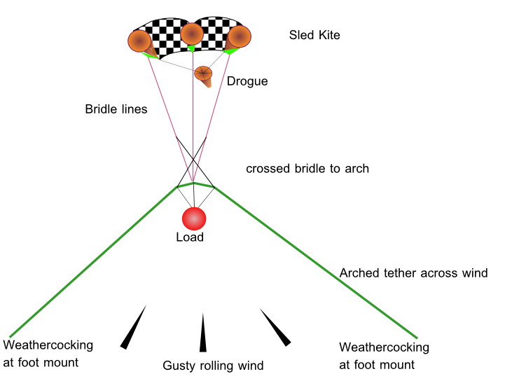
Open developments in “Mothra” single paneled skin, arched loadpath lift kites by Dave Santos of Kitelab and Roderick Read of Windswept and Interesting allow for very large lift structures and arrays to be implemented. Mothra’s use multiple ground anchoring points for safety. Mothra’s can be anchored on radial tracks for weather alignment. Mothra power control is easily adjusted by foot anchor trimming and nose tether. A simple version will be used for initial intended market scale device prototyping and tests. Mothra kites can be flown with or without loading. Thus Daisy rings can be hoisted into place when ready to be set. A Mothra can have various configurations of lift application points, thus Daisy rings can be arrayed to effectively fill the frontal area of the arch.
A narrower post and boom centric version is proposed for initial weather cocking lift models. Wide systems as shown will be applicable to small human movable beach installations.
Wind to Rotary
Very large ram air and inflated kites have already proven successful up to and beyond 300sqm approx 2MW with simple kite window position flight optimization of a single line kite from a ship. The benefits of cross wind kite flight dynamics for stationary ground generation devices are impossible to ignore. Rotary systems which keep the kite in the downwind power zone are ideal. Tether drag is a serious problem for fast kite energy conversion. A rotary system does well by avoiding tethering at the outer tips of rotation.
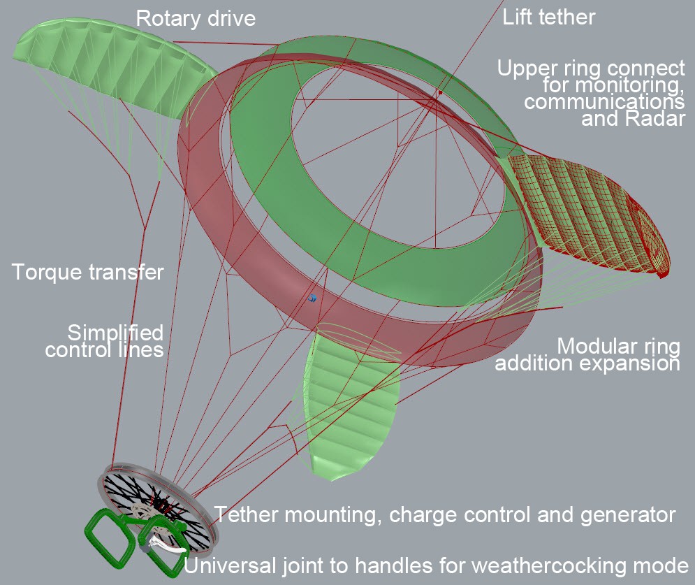
To maintain all of the most desirable flying and energy capture dynamics a ring system of kites was devised.We simplify the design to a parametric algorithmic describing the kite system, whereby the relationship of the number of kites per ring depends on the predicted speed of the foil being used and the radius of rotation. Further parametric relationships describe such as the layering evolution properties of subsequent rings, ring area to kite area ratios, foil setting, tether routing, ring dynamic and panel cutting. Many other system parameter inter relationships have been explored. Designing kites specifically constructed to be faster and tethered from their dynamic root will also help.
Where the lift line links to the rotary set, we used a rollerblade wheel to join the systems in the prototype to good effect.
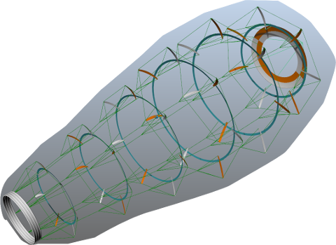
Investigation shows alternative configuration based on more rigid blades inflating their mount ring. Tip to tip tethering as shown is unlikely.
Rotary to electrical
Initial prototype power extraction was demonstrated by driving the kite set against a mountain bike wheel and braking against a squealing disk brake.
For the initial “campsite and ecobuild” scale generation systems we intend to adapt an off the shelf e-bicycle regenerative braking system such as the Falco emotors Hxm2.0 .
The regeneration characteristics of the synchronous motor can be easily programmed to adapt to the current driving characteristics of the kite set by using the existing falco software interface.
An off the shelf inverter should be supplied to compliment the battery system.
Larger scale grid tied systems have more stringent generation control needs and are not a part of the scope of this project. This integration of Daisy kite generator systems with grid systems will occur once a lower levelised cost of energy is demonstrated.
Tethering, Anchoring and Weathercocking
Multi point tethering provides safety through redundancy. The strength to weight ratio afforded by modern rope allows us to build lightweight tethering systems over large spans. It is desirable that failure of any component does not incur catastrophic system failure. This failsafe redundancy design principle includes the tethering of any single component. The Mothra arch and kite ring systems have incorporated this simple design safety principle.
Driver kite tether drag can be reduced dramatically by appropriate bridling, ring layering distance reduction, inter layer tether setting point and appropriately doped tether selection. The goal is basically making less tether move through less air for the same energy transfer.
As the wind moves so too should the whole kite system. This includes the anchoring system.The current prototype has shown itself to be capable of accepting 40deg wind shifts over the Daisy ring frontal surface without total loss of rotation or kite collapse. On initial trials the prototype demonstrated a single unattended inline lightweight parafoil sled lift kite can maintain Daisy to wind over a 3 hour test. However (without dropped base loop line backup) a single inline lift breaks the rule of redundancy. A kite stabilized to the sides of its wind window is a safer and steadier lifter, but the sides need able to weathercock. The weather cocking of spread lift kite tethering needs to be done at a radius greater than the ring kite tip radius. Several open solution proposals exist; ground belay sets set by operators, ring rope and carriage/trolley anchor sets, car anchor sets, rail anchoring, hex meshed lift kite upper ring weather cocking anchoring, hex meshed valley upper ring weather cocking anchoring, turret balanced kite bar booms wider than ring radius.
For the initial camp / ecobuild scale model a simple spread anchored tethering of a Mothra like lift kite is proposed. This model has proven effective already in prototype testing. Tested stabilising results of our tethering system has been welcomed by open science group publiclaboratory.
Software Architecture
In order to maintain inherent system safety we decided to first prove the system without any onboard software necessary to run. However software systems have been invaluable in design and will be invaluable for the potential monitoring, control and communication benefits of the system.
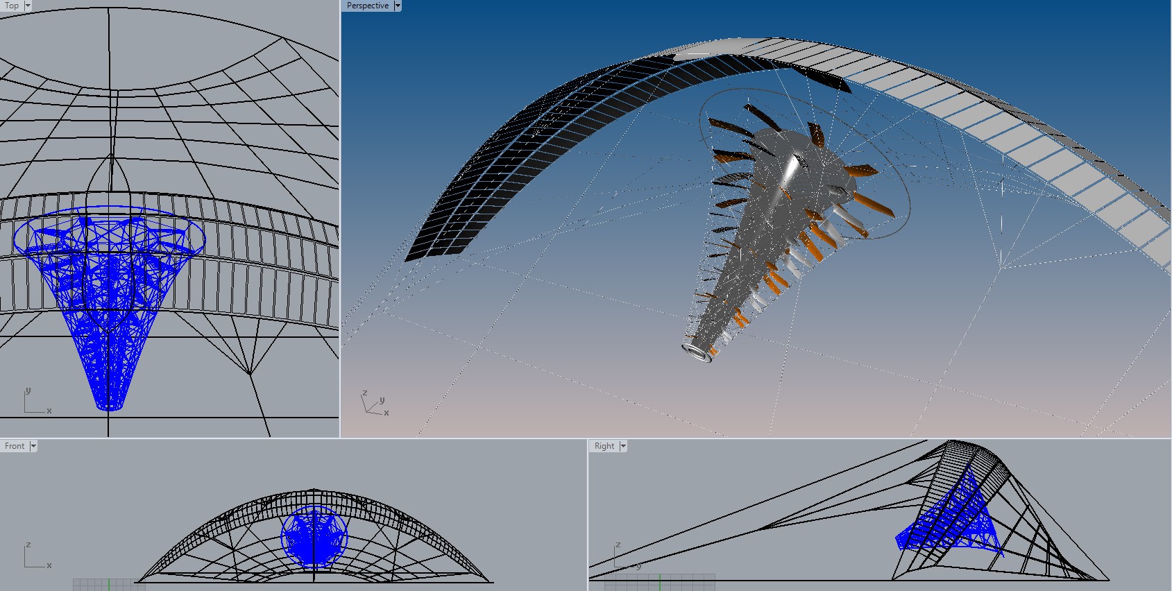
Grasshopper parametric algorithm 3d development language was used to model many possible system configurations before a likely looking prototype was chosen. Likely was based on years of kite experience and feedback from the yahoo AWE forum.
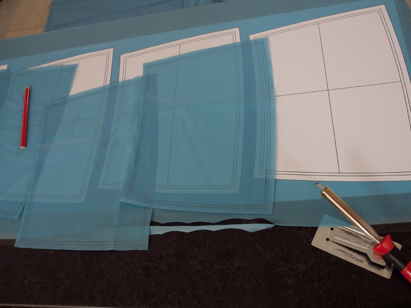
To build the kite kite ring prototype, measurements were first taken from 1.3m ram air kites, which had approx ¼ span (half of the right hand side) removed. Once these sizes were set in grasshopper, the ring chute was developed to fit 3 driver kites. The ring was then divided into smaller parts in multiples of 3 until a neat pattern for bridling and kite mounting was found … and also so that each panel of the ring could be cut from a pattern able to fit on an A3 sheet of paper. Determination of the exact panel shape required used the squish function in Rhino… not an exact surface 2 axis bending tool… but good enough… it worked quite well I think.
NASA machine vision systems are available for experimentation, as are track and control software from TU Delft, other open source kite tracking is also available. Their use has previously been tailored to optimization of kite trajectory in kite yoyo generation systems. It was felt this approach may be too complex for the simple needs of the Daisy system.
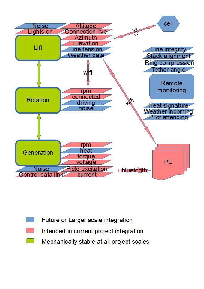
Useful electronics and software can be applied to Kite sheeting power control feedback, Lift kite position monitoring broadcasting and regulation, ensuring top and bottom rpm matching to avoid hockled lines, extended and improved access to radio comms, Falco emotors generator charging control and performance feedback, acoustic analysis of line and bearing performance, inspection, safety lighting, lofted generation for localized operations, weather data, network broadcast availability, line tension data ... and more besides.
For this project I plan to use easily accessible and replicable software platforms with reliable operating systems, simple programming, stock open source wireless solutions… yes old android phones will be repurposed to perform a lot of jobs.An old android phone with wifi tethering makes any kite a valuable new tool in it’s own right. Free software (such as RPMMeter) is available for rpm monitoring using either the accelerometer or the proximity sensor. Giri software can tell you the speed of your gear wheels with acoustic monitoring.
Software demands of heavy duty controls such as would be used on a kite sheeting system with through axis relative tensioning will again need to be made failsafe. This feature will not be attempted in the camping ecobuild scale project. It is a feature very suited to a post and universal joint mounted model.
3d system file models are available from http://kitepowercoop.org or emailing rod directly
Rod dot read at windswept-and-interesting co uk
Communications Architecture
Assuming that the lift kite has a good 3G+ data signal, It is logical to use this as the chief means of accessing kite data remotely. Software such as the “Wireless Tether For Root Users” app for android combined with phone state monitoring software such as stealthgenie can allow recycled phones to take on new uses.
The Falco emotors generator has a proprietary dongle device for remote pc configuration. I think it’s Bluetooth . I’ll explore this further.
File and Database Management
Assuming this device proves popular, it would be best that people with sewing, design, kite, sales, installation and other interests would be able to share in the project.
Details of possible partnerships for delivering a distributed open network enterprise management solution are currently being considered.
HUMAN-MACHINE INTERFACE
Lift kites can be extremely powerful and are not to be toyed with. Thin lines under tension can cut like cheese wire or give really bad friction burns. Special precautions must be taken to ensure safe lift kite operations. Always have correct fitting protective clothing. Operators should always have an emergency rope cutting device available. Never leave a kite which is un doused or readied to launch. Stay upwind of kite surfaces. Keep control lines neatly laid and obvious.
Once the lift kite is launched, prepare the Daisy rings upper end to be hoisted up to flying position. Hold and lift the handles fitted to the daisy generation wheel. Apply the Daisy brake. Hoist the Daisy back end to flying height. If all of the driving kites are set and open ready to drive, Release the brake. If some of the driving kites are collapsed to the inside, slowly release the brake until you can reach the collapsed driver kite, prime the driver kite (throw it outward) and when ready release the brake.
Section still to be completed
DETAILED DESIGN
Hardware Detailed Design
Software Detailed Design
Internal Communications Detailed Design
EXTERNAL INTERFACES
Interface Architecture
Interface Detailed Design
SYSTEM INTEGRITY CONTROLS
-
4Step 4
First steps toward data integration.
The uppermost level lift data will be the most simple to implement. And has in effect already been tested by me logging into my kite then onto the internet over 3G from the ground.
The next step of relaying data from the rotating set will be tricky, and currently it's value will be limited unless rpm data can accurately be cross checked against generation rpm. As I don't want a fast moving heavy brick phone spinning around ... the data is best captured near the top or bottom bearings. If both points are used then referencing coded rotary disk progression becomes more feasible.
However my main problem is going to be understanding and documenting the licensing trail required to transmit the generation data from a falco emotors Hxm2.0 bike generator through the pc over wifi and relaying it to internet.
Daisy Kite Airborne Wind Turbine
Ram air kites spin a parachute and transfer torque to ground
 Roddy "Rags" Read

Discussions
Become a Hackaday.io Member
Create an account to leave a comment. Already have an account? Log In.