Close
0%
0%

Raspberry Pi SDR Cyberdeck

A portable, rugged, self-contained system to suit all your RF SIGINT needs in every environment.

Public Chat
Similar projects worth following
This Raspberry Pi based SDR Cyberdeck is unlike any other as it is based around RF situational awareness.

- Ham radio monitoring
- Spectrum surveillance
- General coverage worldwide HF receiver
- Weather balloon tracking and ranging
- Signal identification
- Quick deployment/mobile operations
- Portable air traffic monitor
- AIS Marine traffic monitoring
- Remote SDR receiver (stream via network)
- Asset tracking
- Weather fax/teletype receiver
- Signals intelligence
- Portable hackstation

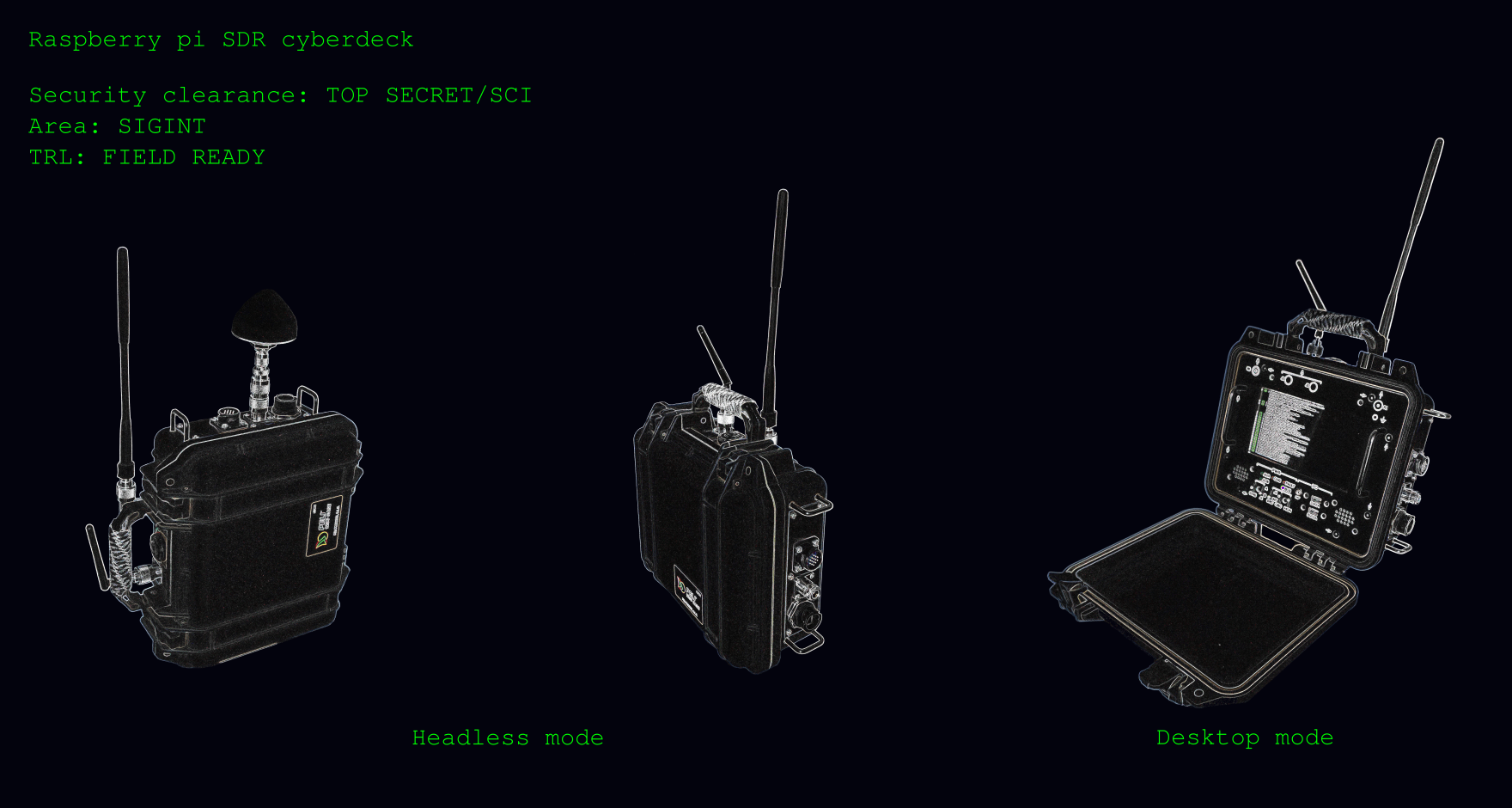
Many Cyberdecks that use Pelicases mostly use the Peli 1300 case, this cyberdeck takes it one step further and integrates everything into a super-compact Peli 1200 case. This shoebox sized unit easily fits into a backpack with room to spare. Official Raspberry Pi 7" touch screen. This unit is all about plug'n play, use the internal powerbank to power the unit, or hookup an external power source between 9-36V from which the internal powerbank can be additionally charged.

Raspberry Pi SDR Cyberdeck

The SDR Cyberdeck is a self-contained unit that allows the operator to adapt to any operational situation where RF monitoring is required. It features built-in GPS, dual channel Software Defined Radio, Real-Time clock, audio system, internal batterypack offering 8+ hours autonomy at normal usage, remote operation via an HTTP REST API, web dashboards for sensor telemetry, VNC for remote control and more...
Hardware

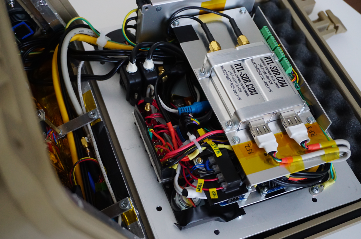
The HW is based around a Raspberry Pi 3 Model B sandwiched between passive cooling elements and a stack of dual Software Defined Radios (SDRs) and power switching, routing, signaling and a small audio system consisting of 2x 3W frontpanel speakers that is driven by the RPi audio 3.5mm jack output.
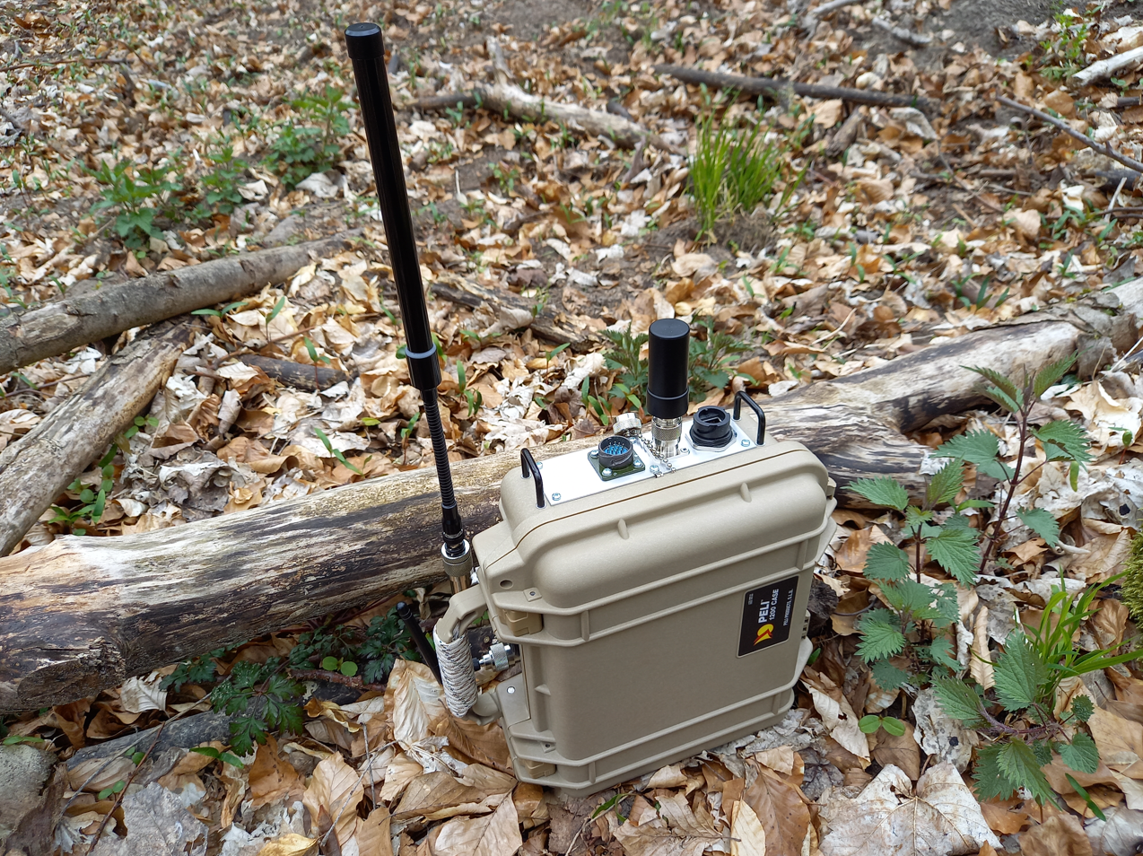
Unit shown in operation below during RF monitoring and surveillance of forest area during training operations. Left antenna is general wideband coverage, smaller stub antenna is an active helix GPS antenna.

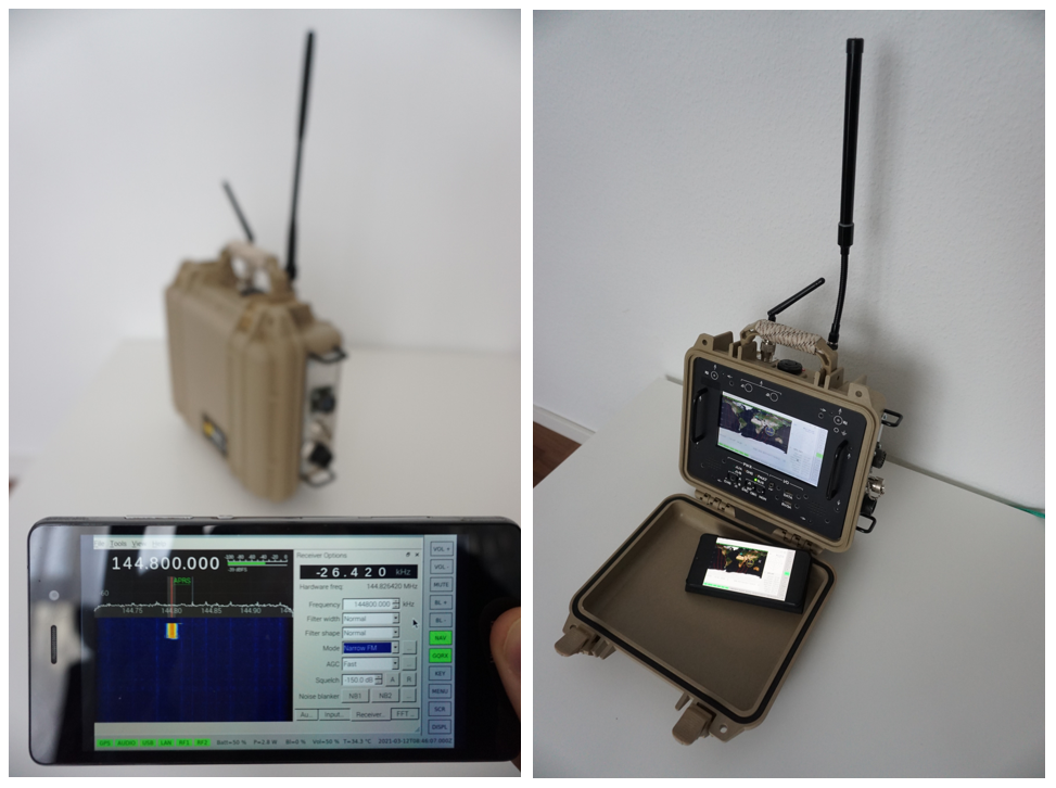
Headless mode:
Spectrum monitoring in headless mode (left), desktop mode with shared session available on remote device (right.)
Software

The Raspberry Pi SDR cyberdeck runs on a software framework with at it's core an ASGI (Asynchronous Server Gateway Interface), in this case uvicorn. The ASGI interface connects to FastAPI which performs the function invocations in the Python threads which control the Devices, Processes and Applications. This allows for easy system manipulation via HTTP1.1 GET/PUT/POSTS methods. The Python threads controlling the processes can range from a commandline decoder to decode APRS via an audio interface, through to starting a VNC session or starting navigation/mapping software. The intention is to make complex application flow, configuration and control easily accessible via the Cyberdeck API interface (which performs HTTP requests to the server), therefore eliminating local commandline interaction with the system. In parallel system data is dumped to an influxdb database, and exposed via Grafana, allowing easy system monitoring over longer periods of time.

The software is still in development and actively maintained at is hosted at GitHub.

Remote Visualisation

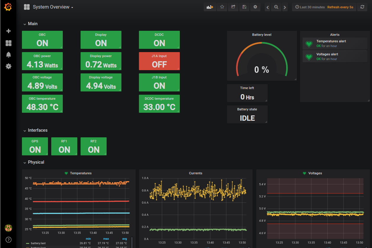
Grafana serves as the entrypoint for any remote visualisation over longer periods of time, or general status monitoring. It can be used to view currents/voltages/temperatures and the status of different peripherals.
Remote Documentation

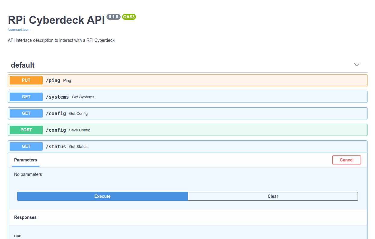
FastAPI has a handy feature where it serves an easy-to-use test interface on http://x.x.x.x:5000/docs. This can be used to test out methods and check if they have the desired effect on the system.
RCC

The remote control client is a simple Python application which uses PyQt5 and grid widgets which get populated based on the structured JSON data that is received via the Cyberdeck API. From this interface, devices can be switched on/off, status monitored, etc...
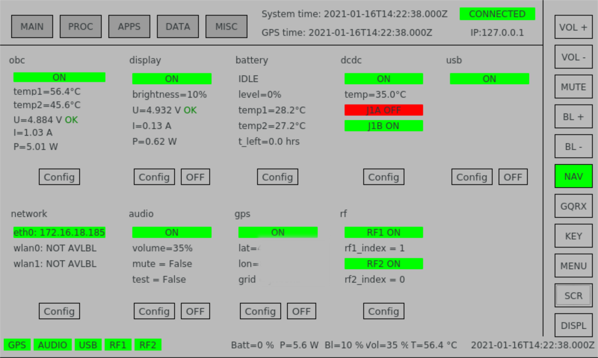
The native size of the GUI is intended for use on the Official Raspberry pi 7" touchscreen.

rpi_cyberdeck_schematics_v2.pdf

Adobe Portable Document Format - 1.30 MB - 01/11/2021 at 22:58

Preview

cyberdeck_frontpanel.svg

Frontpanel drawing, outside dimensions of panel: 237.5 x 182.9 mm

svg+xml - 86.46 kB - 08/14/2020 at 19:39

Preview

  • 1 × Peli 1200 case - color of your choice
  • 1 × Frame for Peli 1200/1300 case Can also be 3D-printed if you want to save some bucks
  • 2 × Hammond Manufacturing rack handle set 1427P1BK (frontpanel rack handles)
  • 2 × Hammond Manufacturing rack handle set 1427B2BK (side panel rack handles)
  • 2 × Miniature speakers type VIS K28.40-8

View all 19 components

  • Patchpanel

    Tom Mladenov01/11/2021 at 23:29 0 comments

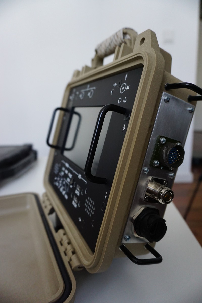
    The last part of the integration consisted of the addition of the side interfacing panel - containing network connection, power and external GPS antenna connector. Early on in the design process, it was chosen to not put these interfaces on the front user panel, as the network and power interface need to be accessible when the unit is closed when operated in remote mode for example. 

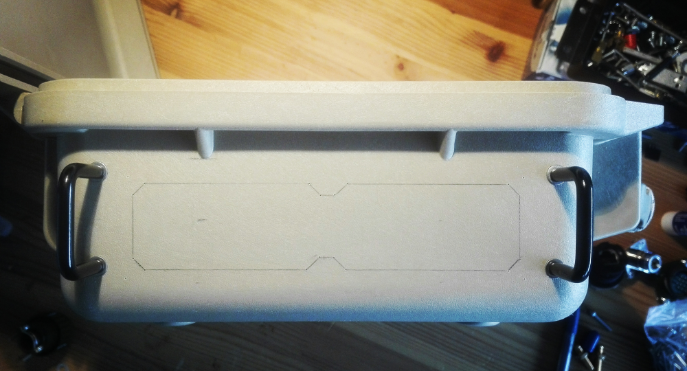
    2 handles (Hammond mfg 1427B2BK) normally used for rack modules were used as connector protection rails if the unit is placed on the respective side. The connectors are mounted in a 2mm thick aluminium plate which is in turn bolted to the case after a back-supporting section was cut out. This has the advantage that another plate with different connectors could still be placed afterwards, or other connectors added, and not needing any modifications of the case itself.

    Finished panel showing the RJ45, GPS antenna and Power connector:

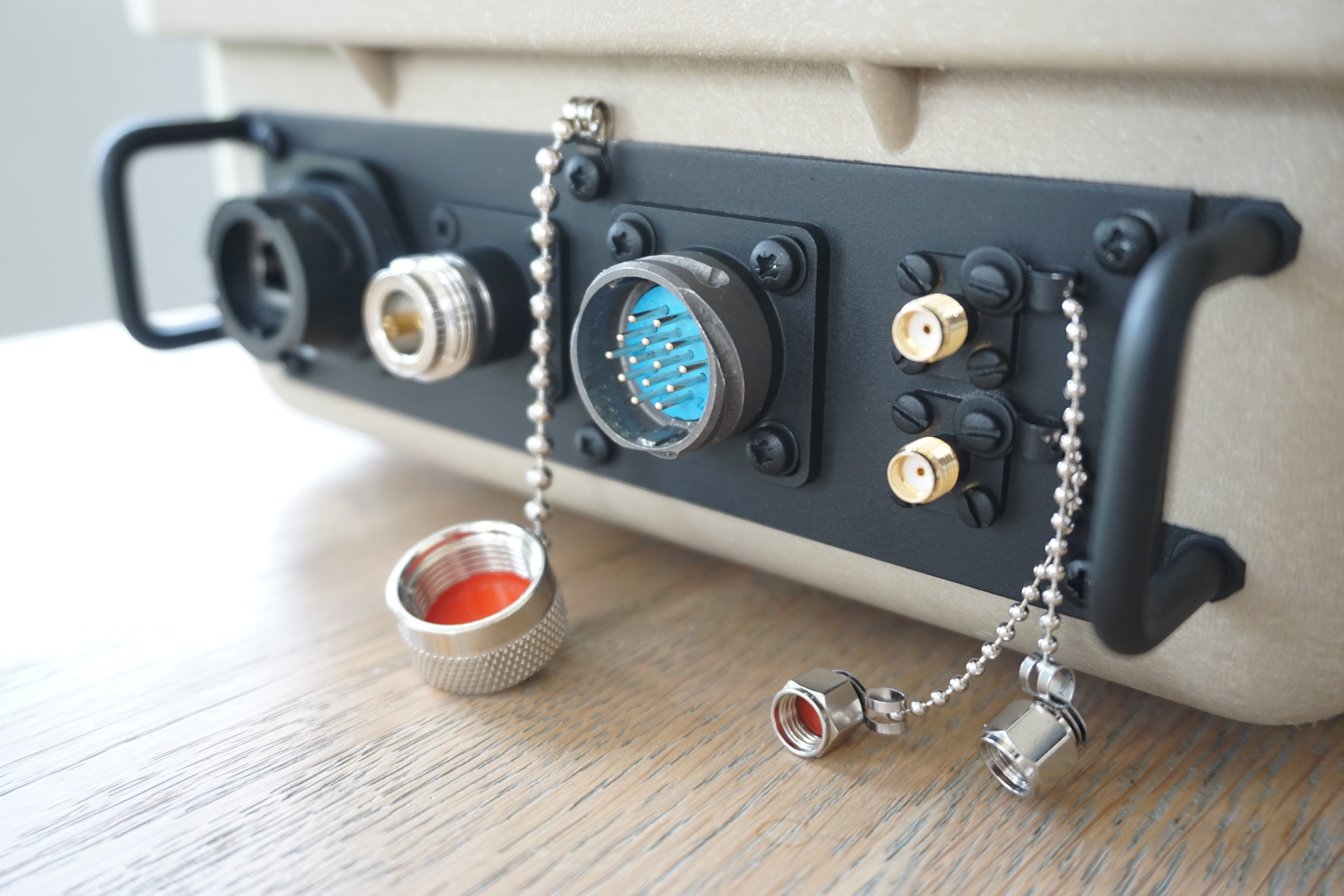
    The finished patchpanel is shown below.

    Connectors from left to right:

    1. Ethernet
    2. N-connector (for external GPS antenna)
    3. Multipurpose 14-pin PWR + IO
    4. 2x SMA (WLAN + auxiliary RF feedthrough)

  • Enabling APRS support

    Tom Mladenov11/03/2020 at 23:48 0 comments

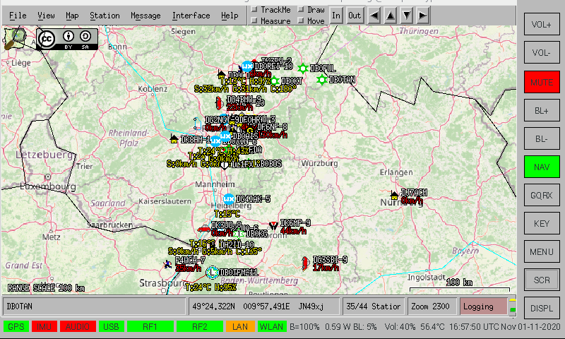
    Support was added to monitor and view APRS (Automatic Packet Reporting System). The concept is that generic data provisioning services (APRS, etc) can be launched with one button without need to run commands or start servers/processes.

    A networked AGWPE engine was added to Xastir with localhost:8000 address.

    To get APRS data, rtl_fm is used to tune to 144.8 MHz (in Europe) and pipe the samples into direwolf which acts as a server and accepts clients connections on port 8000. Upon launching the service from the GUI, the following command is run:

    rtl_fm -M fm -d $INDEX -f 144.800M -s 24000 - | direwolf -t 0 -r 24000 -D 1 -B 1200 - & > /dev/null && echo $! > /home/pi/tmp/aprs.pid

     The .pid file is later used to stop the monitoring using:

    pkill -F /home/pi/tmp/aprs.pid

  • Operation mode concepts

    Tom Mladenov09/07/2020 at 20:20 0 comments

    This log entry covers the various operation modes that are currently being taken into account in designing the power routing and switching of the unit, as well as the usability and accessibility of the communications interfaces.

    To operate the unit, several operational scenarios have been defined and have been separated into user modes and power modes, which can each be combined with each other.

    User modes:

    • Local mode
      • User is in close proximity to the unit and interacts directly with the touch-panel
    • Remote mode - controller
      • Remote mode - (controller) is intended to be used when the user cannot access the unit directly and is closed, but is still in close proximity to the unit. For this purpose it is foreseen to design a small hand controller/handheld unit with a simple dot matrix LCD display to view frequency/mode/GPS info/altimeter/time/... This mode can be used when the unit is in a backpack for example or located in a vehicle without direct access but still required to be operated.
    • Remote mode - Ethernet
      • Remote mode - (Ethernet) is foreseen to be used when the unit is located relatively far away from the user (>10 meters). In this case an Ethernet link is established to the unit via a network cable and all unit operations can be carried out and monitored via a remote computer. Use cases include remote spectrum monitoring for example.

    In the remote modes, the initial setup consists of opening the unit, configuring the desired power mode and then powering the Raspberry Pi. The screen does not need to be powered, saving energy. The unit can then be closed and is ready for remote operations.

    Any of the above user modes can be combined with a power mode below.

    Power modes:

    • Run on internal power
    • Run on 5VDC external power
    • Run on 9-36VDC external power
    • Run on 5VDC external power + charge internal powerbank
    • Run on 9-36VDC external power + charge internal powerbank
    • Run on 5VDC external power + charge internal powerbank from 9-36VDC input
    • Run on 9-36VDC external power + charge internal powerbank from 5VDC input

  • Adding shielding

    Tom Mladenov09/01/2020 at 21:29 0 comments

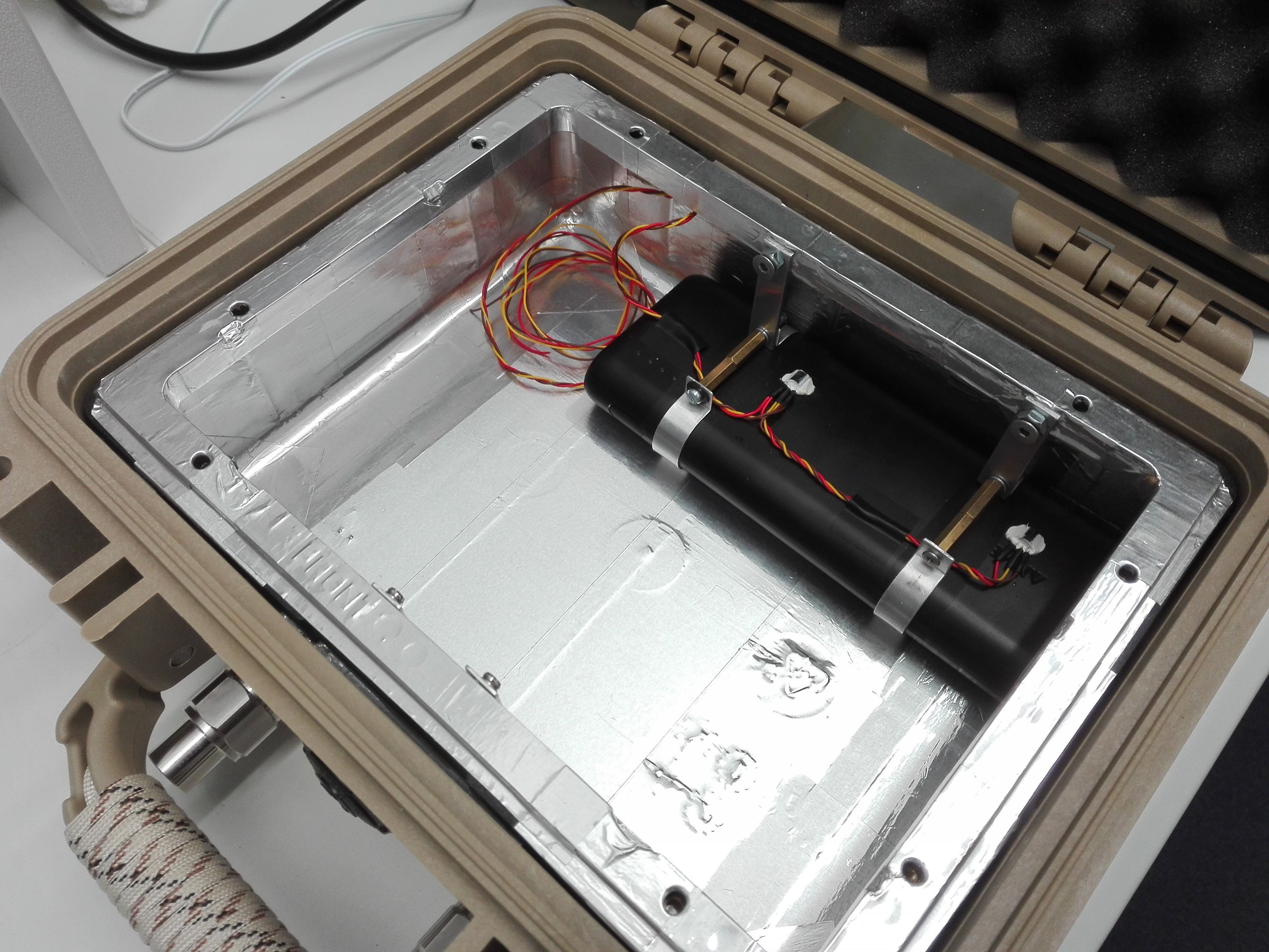
    Shielding has been added to the inside of the unit using aluminium foil tape. The backside of the frontpanel makes contact with the aluminium tape strips that extend over the edges of the panel frame. An opening was left in the shielding for GPS antenna at the top.

  • GPS Module Integration

    Tom Mladenov08/14/2020 at 19:27 0 comments

    Bench tests indicated an active GPS antenna placed under the top of the Cyberdeck acquired plenty of satellites with good signal strength, hence the next step was an internal GPS module.

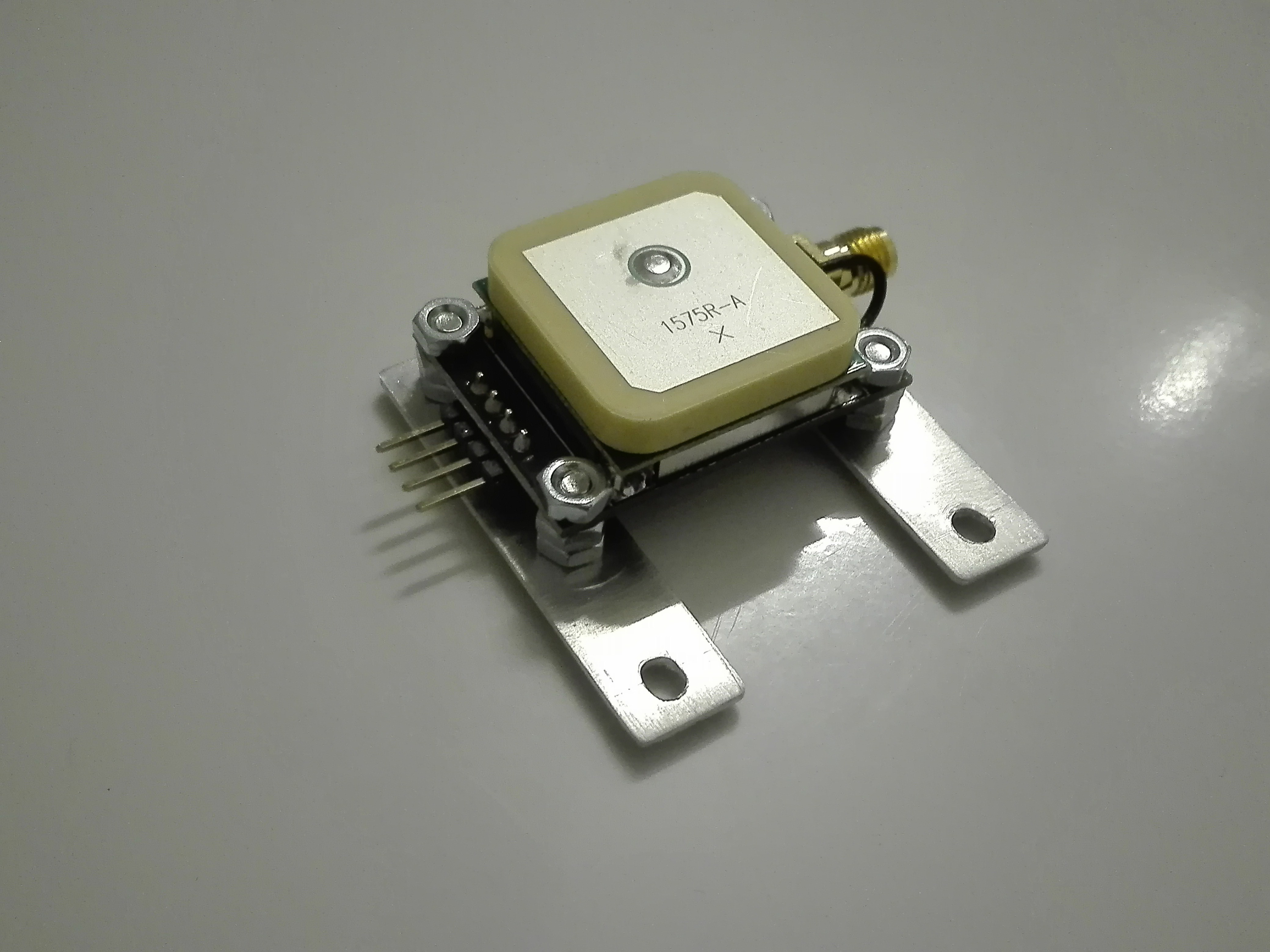
    The active patch antenna and corresponding NEO-6M receiver PCB conveniently had exposed PCB pads which were used to solder the 2 together forming a stack. An SMA connector was additionally soldered to the exposed pads on the receiver board to facilitate an external antenna when the unit is being used inside a vehicle for example. After some brackets and screws the unit is ready for integration. 

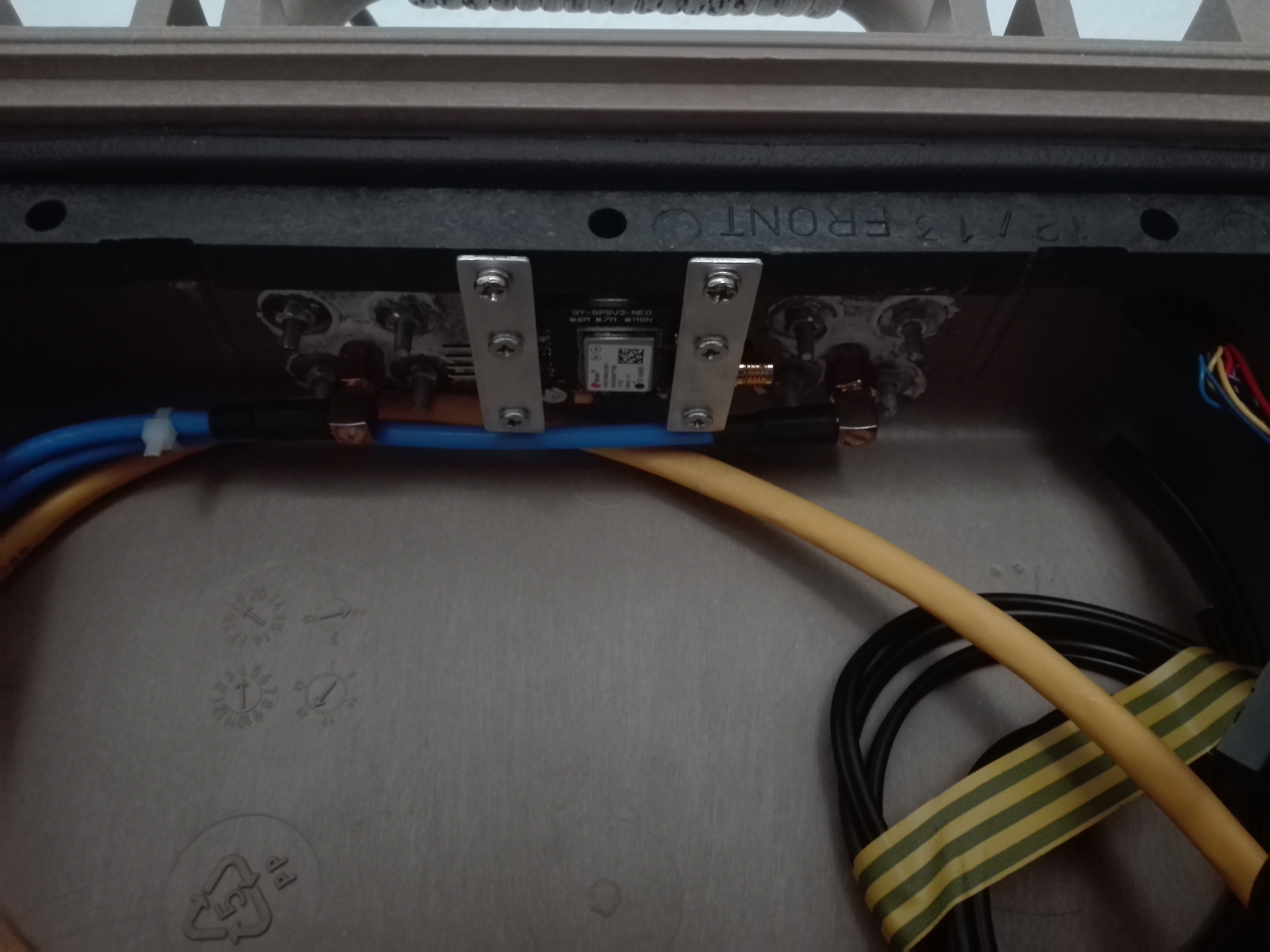
    2x M3 inserts were inserted into the inside of the panel frame and secured with bolts and locking washers. (Note the white silicone in the background for the waterproofed N-connector feedthroughs, maintaining the case's IP-rating).

View all 5 project logs

Enjoy this project?

Share

Discussions

equinitry wrote 09/03/2020 at 17:34 point

Like it! Nice idea with the Aluminium foil for shielding^^

  Are you sure? yes | no

Devin St. Clair wrote 08/19/2020 at 22:20 point

Great looking project, instructions and even a RaspberryPi image that has all the software and configurations would be greatly appreciated.

  Are you sure? yes | no

Dan Maloney wrote 08/17/2020 at 20:17 point

Nice! Been thinking about building something like this for a while. Maybe now that I have something to copy -- err, inspiration -- I'll give it a whirl. Thanks!

  Are you sure? yes | no

Tom Mladenov wrote 08/18/2020 at 17:13 point

Cool Dan! Good luck in the build. Expect some more updates here over the following days/weeks as I add some features/clear up some details.

  Are you sure? yes | no

Similar Projects

Does this project spark your interest?

Become a member to follow this project and never miss any updates