Tom Mladenov
-
Patchpanel
01/11/2021 at 23:29 • 0 commentsThe last part of the integration consisted of the addition of the side interfacing panel - containing network connection, power and external GPS antenna connector. Early on in the design process, it was chosen to not put these interfaces on the front user panel, as the network and power interface need to be accessible when the unit is closed when operated in remote mode for example.
![]()
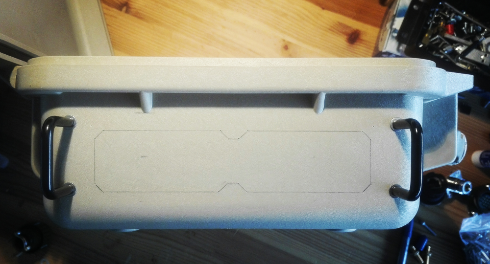
2 handles (Hammond mfg 1427B2BK) normally used for rack modules were used as connector protection rails if the unit is placed on the respective side. The connectors are mounted in a 2mm thick aluminium plate which is in turn bolted to the case after a back-supporting section was cut out. This has the advantage that another plate with different connectors could still be placed afterwards, or other connectors added, and not needing any modifications of the case itself.
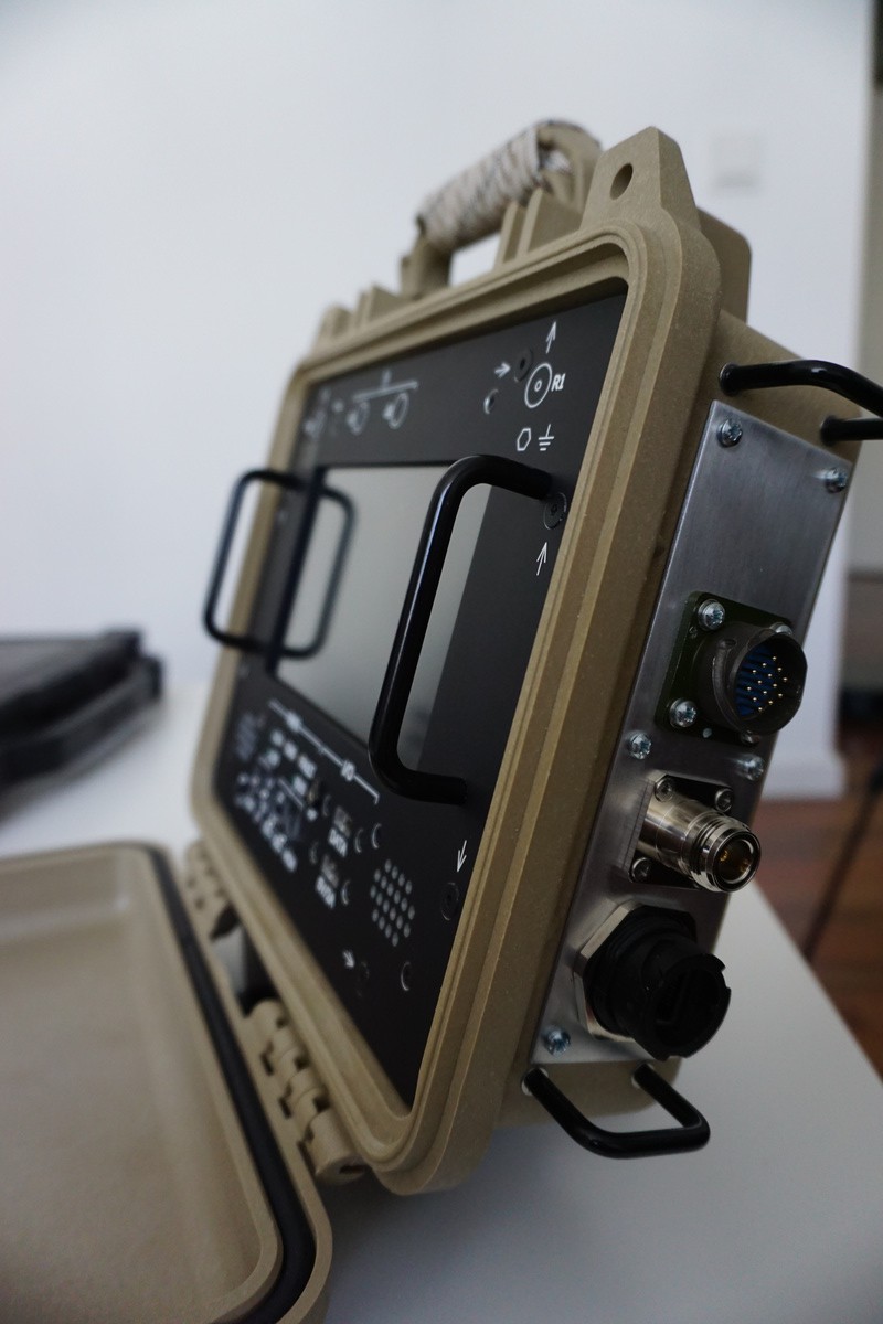
Finished panel showing the RJ45, GPS antenna and Power connector:
![]()
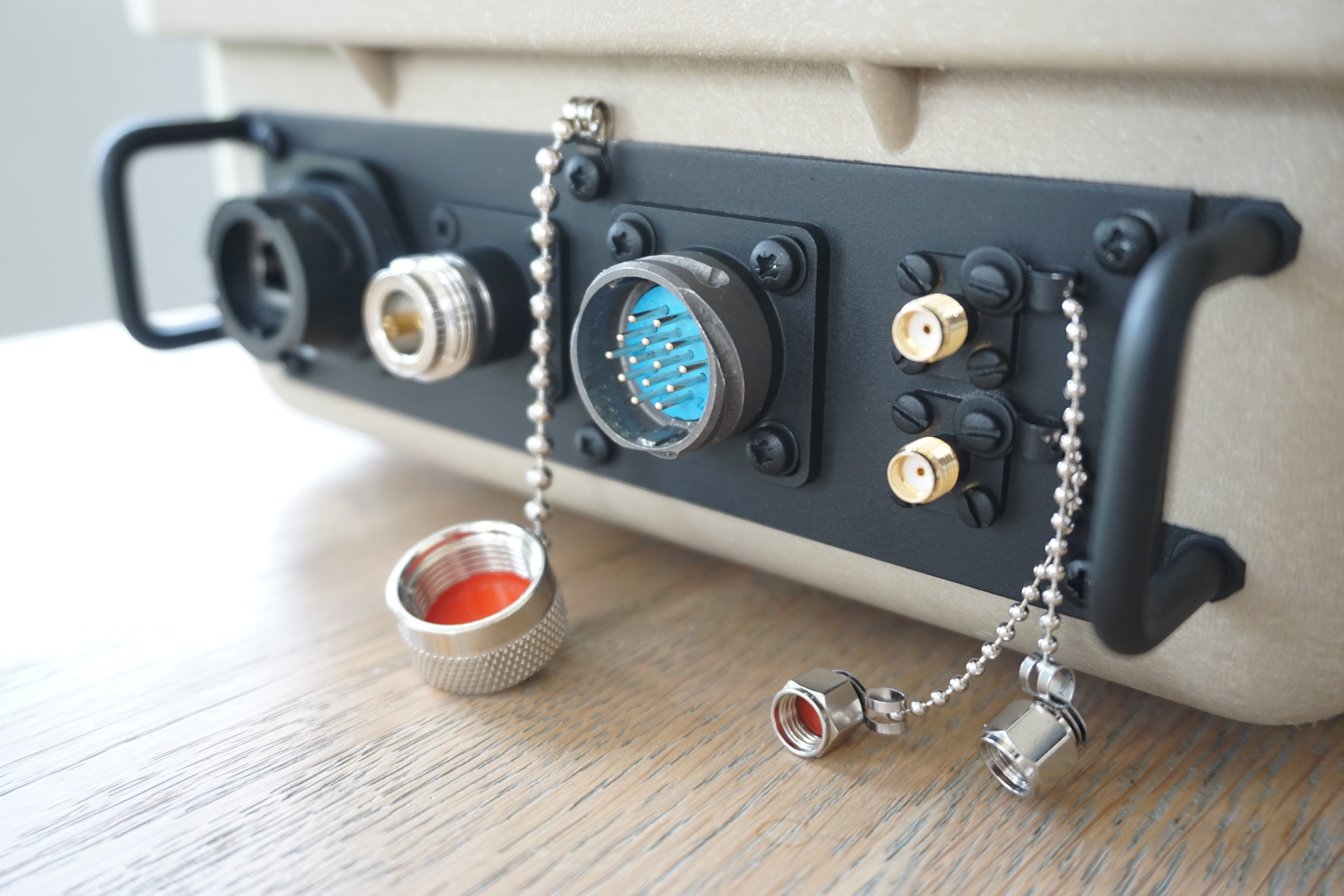
The finished patchpanel is shown below.
Connectors from left to right:
- Ethernet
- N-connector (for external GPS antenna)
- Multipurpose 14-pin PWR + IO
- 2x SMA (WLAN + auxiliary RF feedthrough)
![]()
-
Enabling APRS support
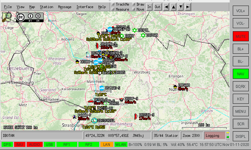
11/03/2020 at 23:48 • 0 commentsSupport was added to monitor and view APRS (Automatic Packet Reporting System). The concept is that generic data provisioning services (APRS, etc) can be launched with one button without need to run commands or start servers/processes.
![]()
![]()
A networked AGWPE engine was added to Xastir with localhost:8000 address.
To get APRS data, rtl_fm is used to tune to 144.8 MHz (in Europe) and pipe the samples into direwolf which acts as a server and accepts clients connections on port 8000. Upon launching the service from the GUI, the following command is run:
rtl_fm -M fm -d $INDEX -f 144.800M -s 24000 - | direwolf -t 0 -r 24000 -D 1 -B 1200 - & > /dev/null && echo $! > /home/pi/tmp/aprs.pidThe .pid file is later used to stop the monitoring using:
pkill -F /home/pi/tmp/aprs.pid -
Operation mode concepts
09/07/2020 at 20:20 • 0 commentsThis log entry covers the various operation modes that are currently being taken into account in designing the power routing and switching of the unit, as well as the usability and accessibility of the communications interfaces.
To operate the unit, several operational scenarios have been defined and have been separated into user modes and power modes, which can each be combined with each other.
User modes:
- Local mode
- User is in close proximity to the unit and interacts directly with the touch-panel
- Remote mode - controller
- Remote mode - (controller) is intended to be used when the user cannot access the unit directly and is closed, but is still in close proximity to the unit. For this purpose it is foreseen to design a small hand controller/handheld unit with a simple dot matrix LCD display to view frequency/mode/GPS info/altimeter/time/... This mode can be used when the unit is in a backpack for example or located in a vehicle without direct access but still required to be operated.
- Remote mode - Ethernet
- Remote mode - (Ethernet) is foreseen to be used when the unit is located relatively far away from the user (>10 meters). In this case an Ethernet link is established to the unit via a network cable and all unit operations can be carried out and monitored via a remote computer. Use cases include remote spectrum monitoring for example.
In the remote modes, the initial setup consists of opening the unit, configuring the desired power mode and then powering the Raspberry Pi. The screen does not need to be powered, saving energy. The unit can then be closed and is ready for remote operations.
Any of the above user modes can be combined with a power mode below.
Power modes:
- Run on internal power
- Run on 5VDC external power
- Run on 9-36VDC external power
- Run on 5VDC external power + charge internal powerbank
- Run on 9-36VDC external power + charge internal powerbank
- Run on 5VDC external power + charge internal powerbank from 9-36VDC input
- Run on 9-36VDC external power + charge internal powerbank from 5VDC input
- Local mode
-
Adding shielding
09/01/2020 at 21:29 • 0 commentsShielding has been added to the inside of the unit using aluminium foil tape. The backside of the frontpanel makes contact with the aluminium tape strips that extend over the edges of the panel frame. An opening was left in the shielding for GPS antenna at the top.
![]()
-
GPS Module Integration
08/14/2020 at 19:27 • 0 commentsBench tests indicated an active GPS antenna placed under the top of the Cyberdeck acquired plenty of satellites with good signal strength, hence the next step was an internal GPS module.
The active patch antenna and corresponding NEO-6M receiver PCB conveniently had exposed PCB pads which were used to solder the 2 together forming a stack. An SMA connector was additionally soldered to the exposed pads on the receiver board to facilitate an external antenna when the unit is being used inside a vehicle for example. After some brackets and screws the unit is ready for integration.
![]()
2x M3 inserts were inserted into the inside of the panel frame and secured with bolts and locking washers. (Note the white silicone in the background for the waterproofed N-connector feedthroughs, maintaining the case's IP-rating).
![]()
Raspberry Pi SDR Cyberdeck
A portable, rugged, self-contained system to suit all your RF SIGINT needs in every environment.