Paul McClay
-
sane(ish) AC achieved, I think -- and bootstrap circuit board
04/19/2024 at 01:17 • 0 commentsLog catch-up campaign: closing in on caught up so I can get back to work getting ahead of logs again.
So I've got this box with a few compartments and a plan to keep all the AC power wiring in the top compartment in order to separate "high" voltage from low voltage DC.
This iteration of the AC stuff seems to be at least ok. For me; for now.
![]()
I've made this harder for myself by chasing conflicting ̶r̶e̶q̶u̶i̶r̶e̶m̶e̶n̶t̶s̶ aspirations.
And I don't know jack about "best practices" for making stuff with line voltage AC in it. If I may quote myself from elsewhere:
Dear reader: this is random Internet "content" by an unqualified author for entertainment only. Misuse of [mains AC] can kill you and burn your house, which may entail killing other people. How to do anything with [AC] other than what the label says without burning stuff or killing people is beyond the scope of this writeup. Consider this first-person account as a pre-staged footnote for my eventual Darwin Award and not as instructions for anything you should do.
For AC stuff, I wanted
- onboard DC supply
- inlet - because I wanted a clean box exterior without a hardwired cord (hardwired out the top was an option)
- fuse
- switch
- relay-switched outlet for "spindle"
- logic-switched relay
- US ungrounded, polarized outlet (NEMA 1-15R)
Not rocket science.
I figured that could fit in something less than all of the volume of the upper compartment, leaving some room to stash stuff like the power cord and most of the dremeloid cord. I started out thinking that would get done with a simple partition to divide the space into AC (closed) and storage (open). But I didn't come up with a simple partition that seemed like a good use of the space. Which got me thinking about a less simple, more conformal, probably 3d printed, enclosure for the AC stuff inside that compartment. Which lead to greed for the most space for storage which meant fitting the AC stuff into the least space without crowding stuff that shouldn't touch or mashing soft insulation between hard parts.
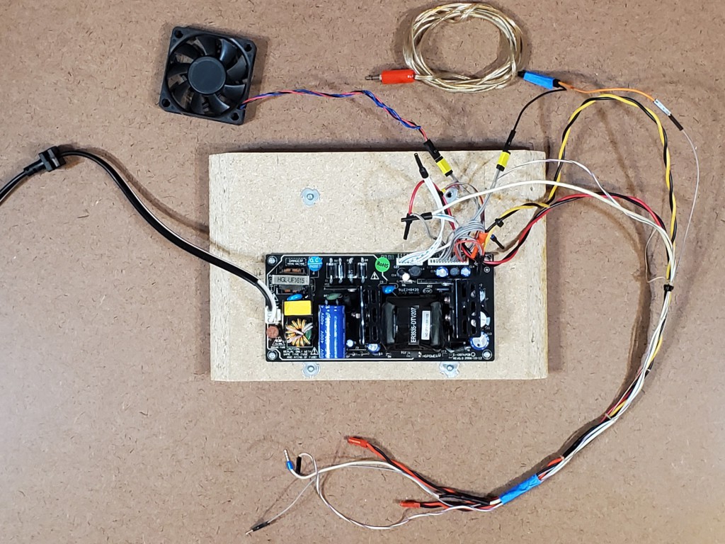
For this iteration, I decided to use a double-insulated power brick with a C8 inlet for the benefits of having that already robustly enclosed/insulated and also the more compact power cord vs the common grounded 15A "IEC" type (i.e. C13) cord.
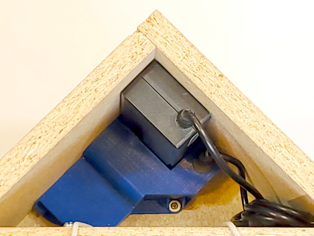
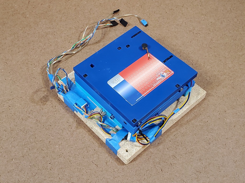
The Unified AC Widget fits into the corner with the power supply.
![]() The DC-out cord from the supply could be cut down to the minimum needed to make the connection.
The DC-out cord from the supply could be cut down to the minimum needed to make the connection.
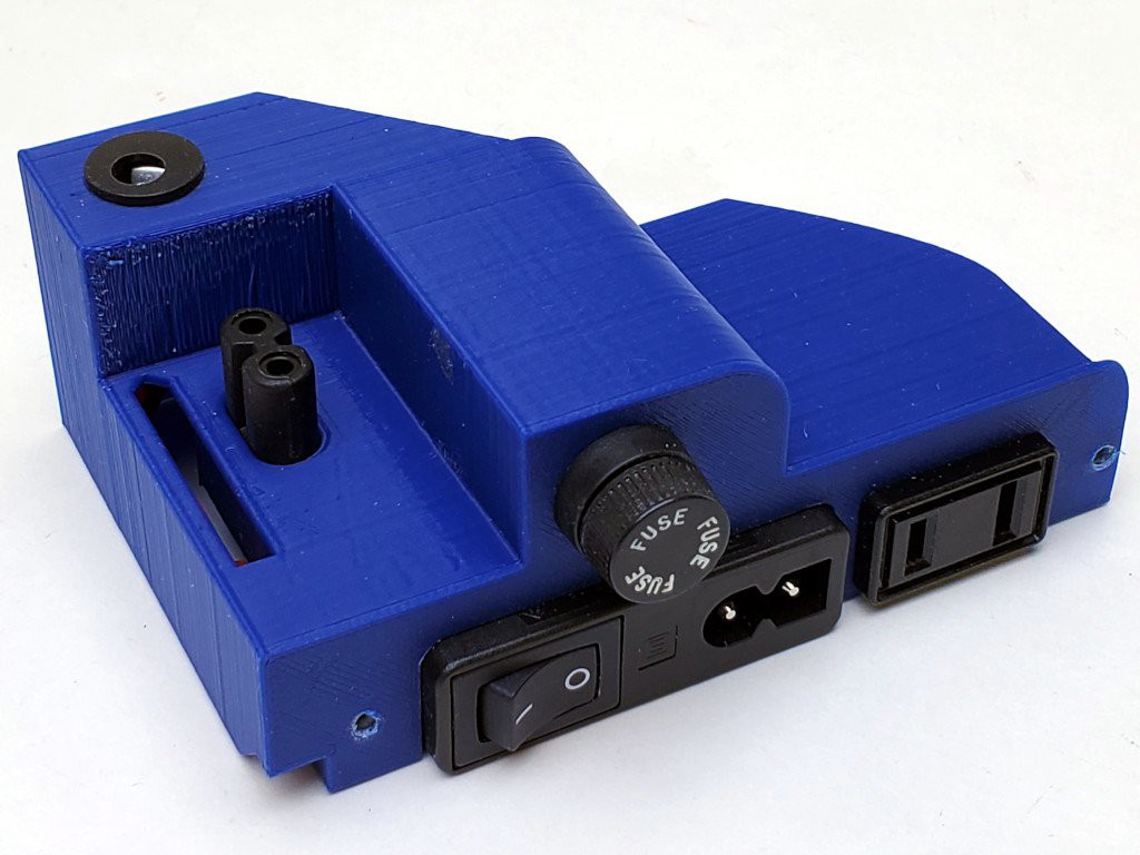
Cutouts in the back wall of the box expose the interactive bits.
![]()
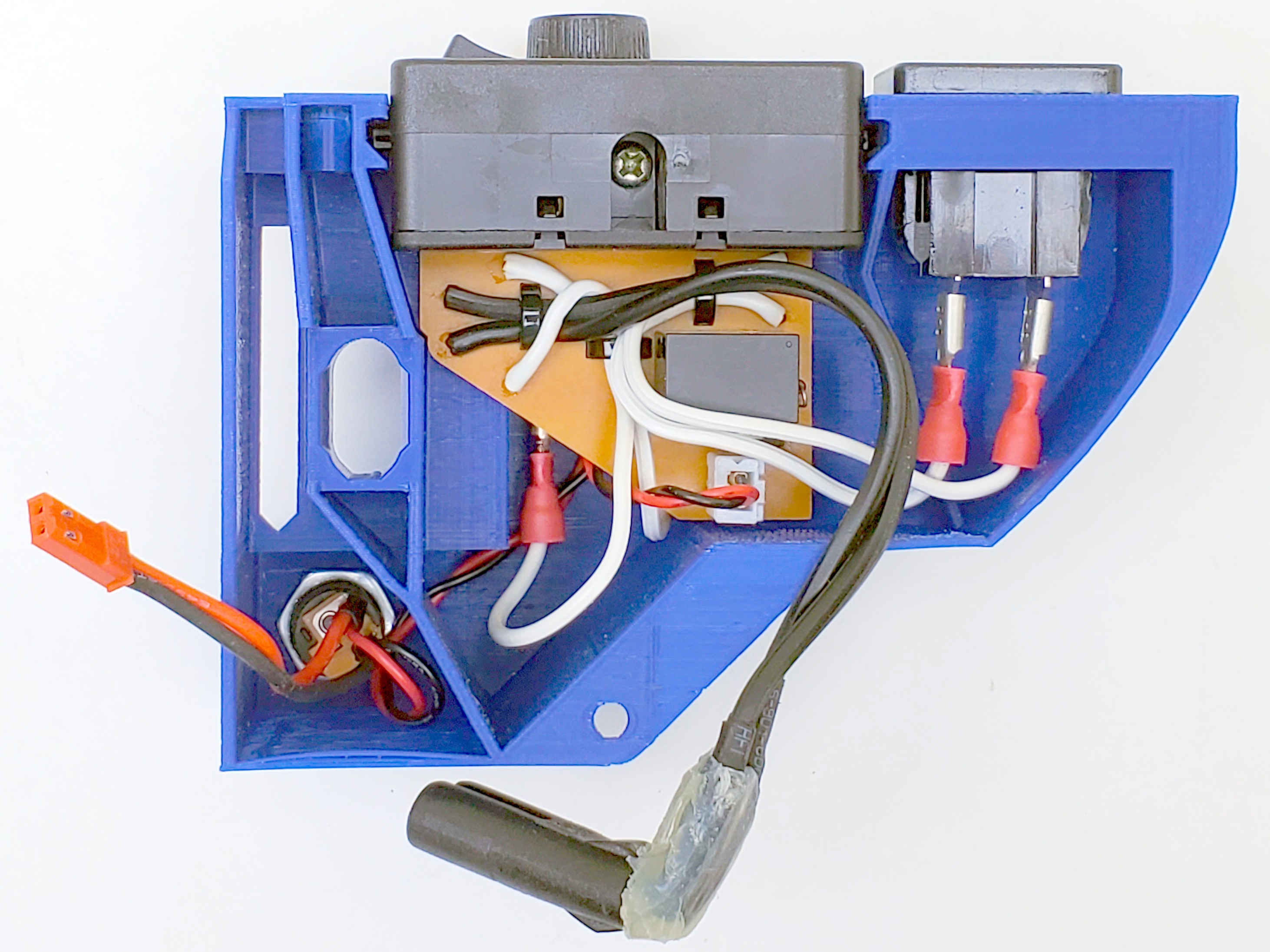
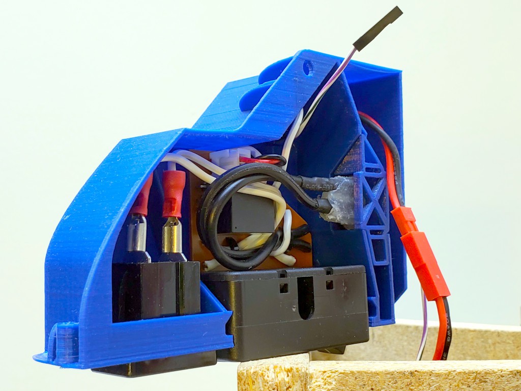
Stuff inside is compact without crowding.
![]()
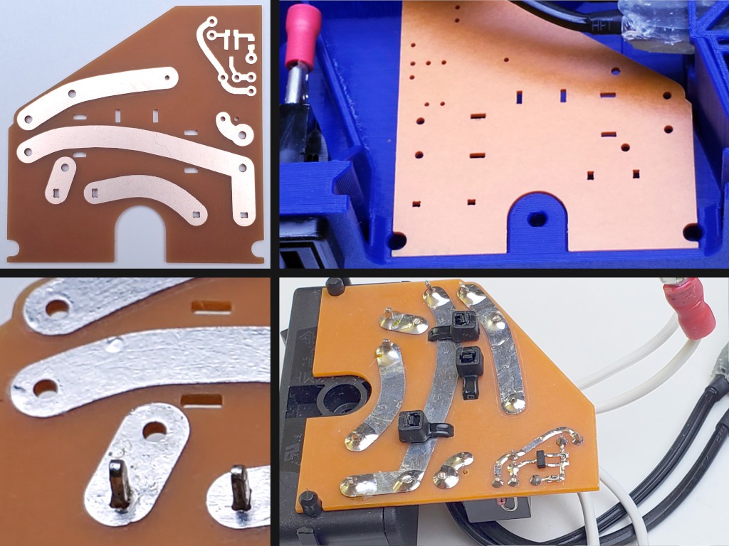
In addition to the inlet/outlet/fuse/switch out the back, this includes a ̶b̶u̶t̶c̶h̶e̶r̶e̶d̶ right-angle C7 plug for the power brick, the red connector for 12VDC power down to the low voltage electronics & motors below, and the mostly hidden connector for the logic-level spindle enable signal coming back up. A second tap off the DC input jack feeds the relay coil, relying on the relay & trace separation on the circuit board for galvanic isolation from the high voltage stuff.
If I build this configuration again, I'll get a right-angle plug for the power supply instead of farting around for the usual longer-than-expected time to make one with random dimensions.
I should probably use insulated quick-connects or some such to make this unit itself more nearly something like double insulated.
The circuit board helps compactify this and make it less of a crammed jumble of wires. That was something of a flag day for the project:
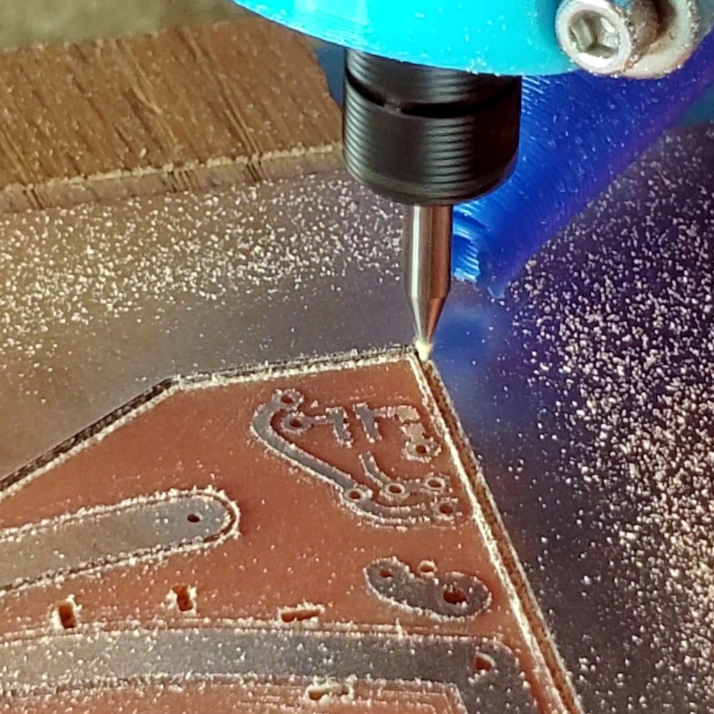
Minamil mills a circuit board for itself
![]()
I think that's kind of a thing. Part of the RepRap quest is (was, now that manufactured 3d printers are cheaper than BoM for DIY) the self-replicating machine that can make its own wiring. Here, with very little additional hardware, a 3d printer can print a very little sidekick that can make circuit boards.
![]()
Lessons learned from earlier iterations include:
- this needs to be disconnectable from the writing that stays with the frame
- dis/connecting stuff in the bottom of a deep hole is hard
- hoping a bunch of extra wire can be randomly stuffed into a small space isn't a great plan
As applied in this iteration, that looks like:
![]()
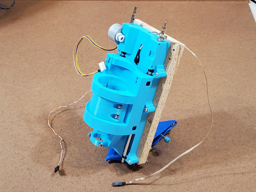
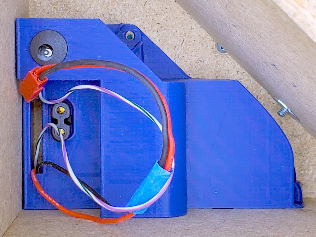
The DC supply and spindle signal to/from elsewhere in the box are disconnectable and long enough to reach up out of the top of the box where they can be dis/connected by human fingers
![]()
A slot in the AC unit allows the extra wire length to be pulled up through the slot while pushing the AC unit down into place.
![]()
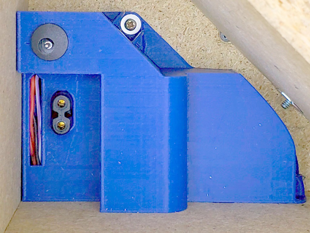
Once the AC unit is secured in place, the extra wire may be folded back down through the slot into a well-defined space where it does not crowd anything else
When worlds don't really collide
I burned a lot of time sorting this out and some more time starting a few drafts of long(er)-winded writeup. Bah. Here's the short version:
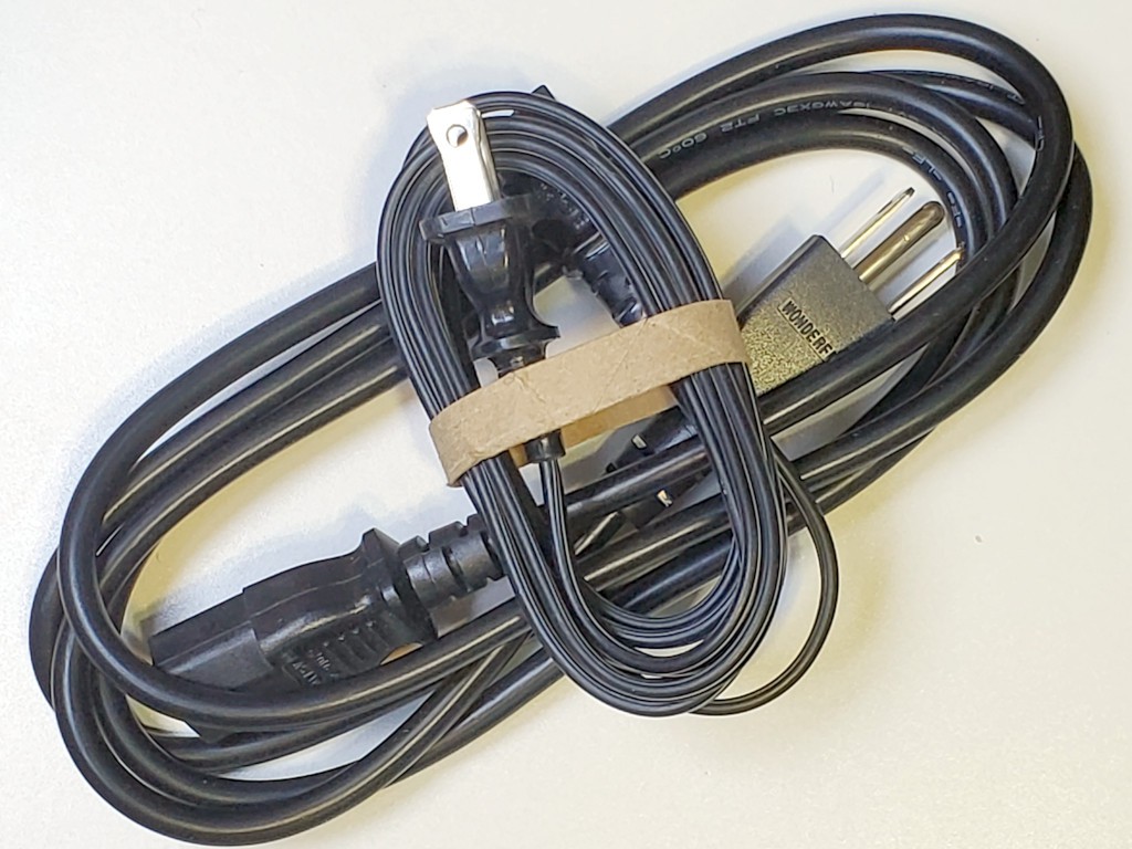
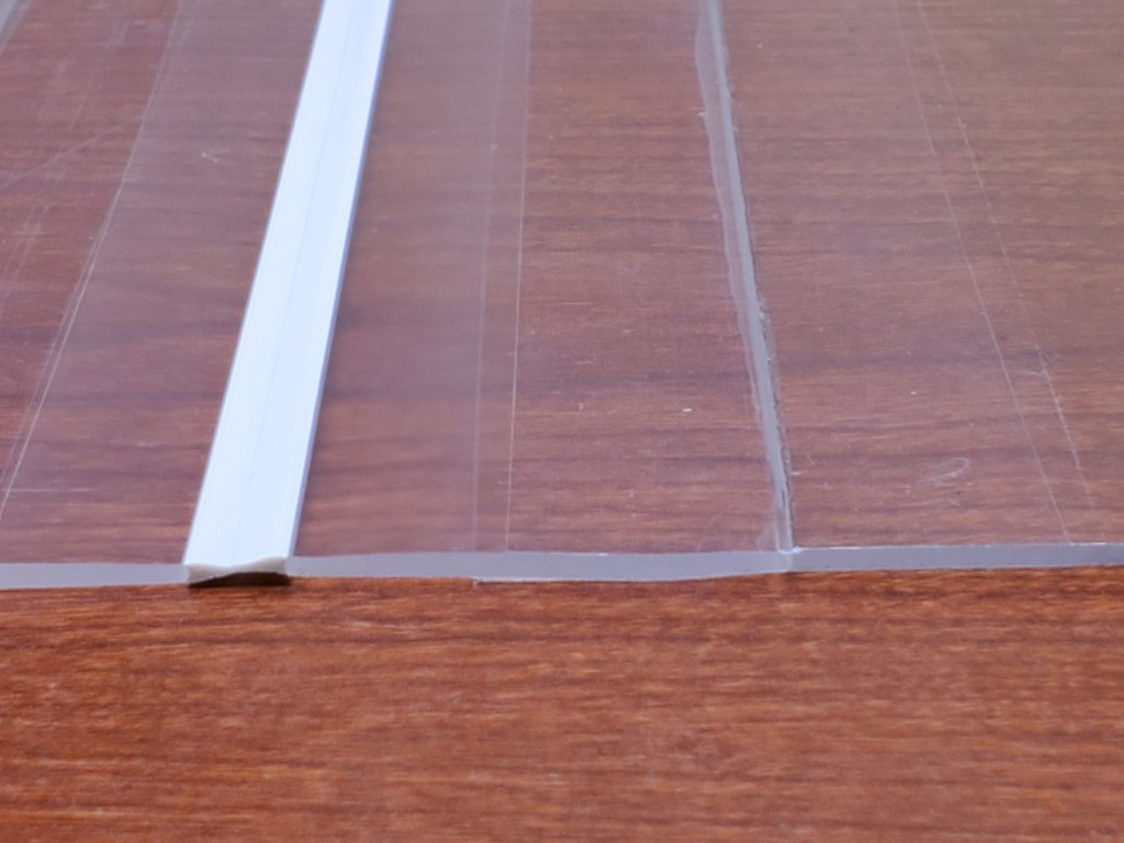
Along with wanting more free space up top for storage, I also wanted to fill less of it with a less bulky power cord than the usual 15A three-conductor "IEC" cord (C13) and I had an attractive candidate.
![]()
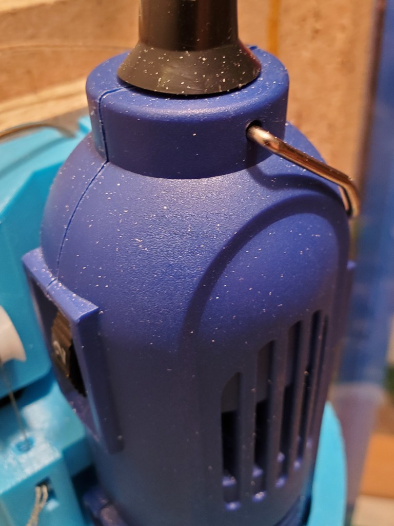
big cord, little cord -- same length That cord has a plug that's a lot like a C7 plug that would fit the power brick, but polarized. "Polarized C7" cords are easy to find in abundance. Polarized C8 inlets? Not so much. In fact "Polarized C7/C8" does not exist in the IECverse. Polarized "C8" inlets exist (e.g. top photo) but not nearly as easy to find or in such abundance as the plugs. (So where do the things the plugs plug into come from?)
-and-
My dremeloid rotary tool has a polarized ungrounded plug. Apparently because I live in the US (North America). Why? Dunno. It's marked as double insulated and the same thing is sold in other highly regulated markets with an unpolarized plug. The US (NA) retains a concept of polarized ungrounded power and receptacles accept polarized plugs. I supposed that's a good thing for old school Edison-type lamp sockets in fixtures that wontonly expose the threaded cup. But the same receptacles also accept unpolarized plugs so the receptacles didn't force the maker's choice of plug, and the same maker sells the same tool with unpolarized plugs elsewhere. Shrug.
So: US(NA) -> polarized plug; polariized plug -> needs polarized outlet; polarized outlet -> needs polarized inlet.
Alternatively, I could have cut down the neutral blade to fit an unpolarized outlet. But I was already publishing my progress at this, and that seemed like the sort of thing best done in private. Or I could have fed the polarized outlet from an unpolarized inlet, but that would ... just No.
If I wasn't bent on using the less bulky cord, or living in the US(NA), I could have used any of many lovely integrated inlet+fuse+switch units and moved on. If I lived somewhere else, I'd have spent a lot less time never learning that this was an issue at all.
(aside: For whatever their reasons, people want a polarized ungrounded appliance power inlet receptacle/plug and fie on the committee who would stop them from having it. For various reasons, the apparently accepted pirate C7/C8 variant was a poor choice. But I'm going to punt from writing any more about this.)
- onboard DC supply
-
am not electrician
04/18/2024 at 22:11 • 0 commentsContinuing the log catch-up campaign...
Earlier I mentioned keeping all the AC power wiring in the top of the frame, with intent to include a logic-switched power outlet for the "spindle".
I'm going to mostly skip a couple iterations of "improving" that because:
- it will expedite the log catch-up campaign, and
- I'm not an electrician and sometimes do dumber stuff than usual that's easier to pretend didn't happen if I don't write Log pages about it.
I did manage a first whack at fitting logic switched spindle power inside the box, so here's a few pix.
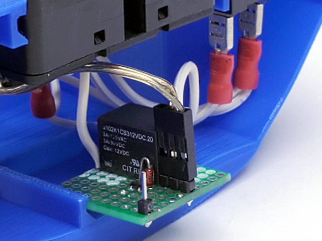
![]()
Relay in the hot wire to a 1-15R outlet (the usual US two-prong polarized -- because that's the plug on my US market dremeloid).
12VDC supply for the relay coil.
Header pin for the "spindle enable" signal.
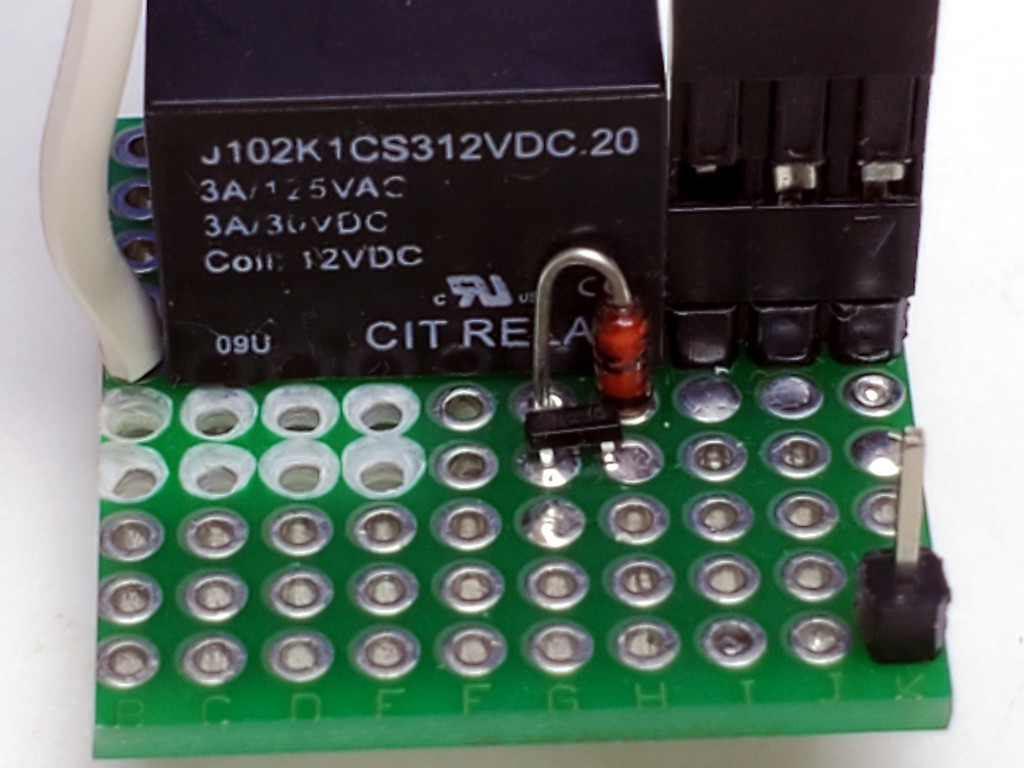
![]()
Signal pin and FET for switching coil power (coil supply ground is common with the controller).
Flyback diode because conventional wisdom says "flyback diode" -- no math attempted.
Plated thru-holes de-plated for HV/LV isolation.
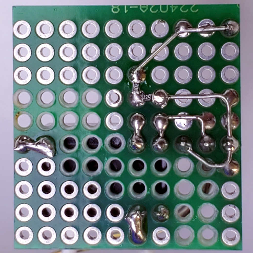
![]()
Resistors under the FET: gate pulldown and a "protection" resistor because resistors between stuff and off-board connections make me feel gooder. Am not EE.
Using a 3 position header and wiring the end pins together makes an easy non-polarized connection for coil power. I don't remember where I saw that trick.
-
vent fan
04/16/2024 at 05:37 • 0 commentsAfter cutting stuff, I often see evidence of dust getting up to the top of the works...
![]()
...which I suppose indicates dust escaping entirely. For various reasons that wouldn't be great even I wasn't doing this inside the living space of my home.
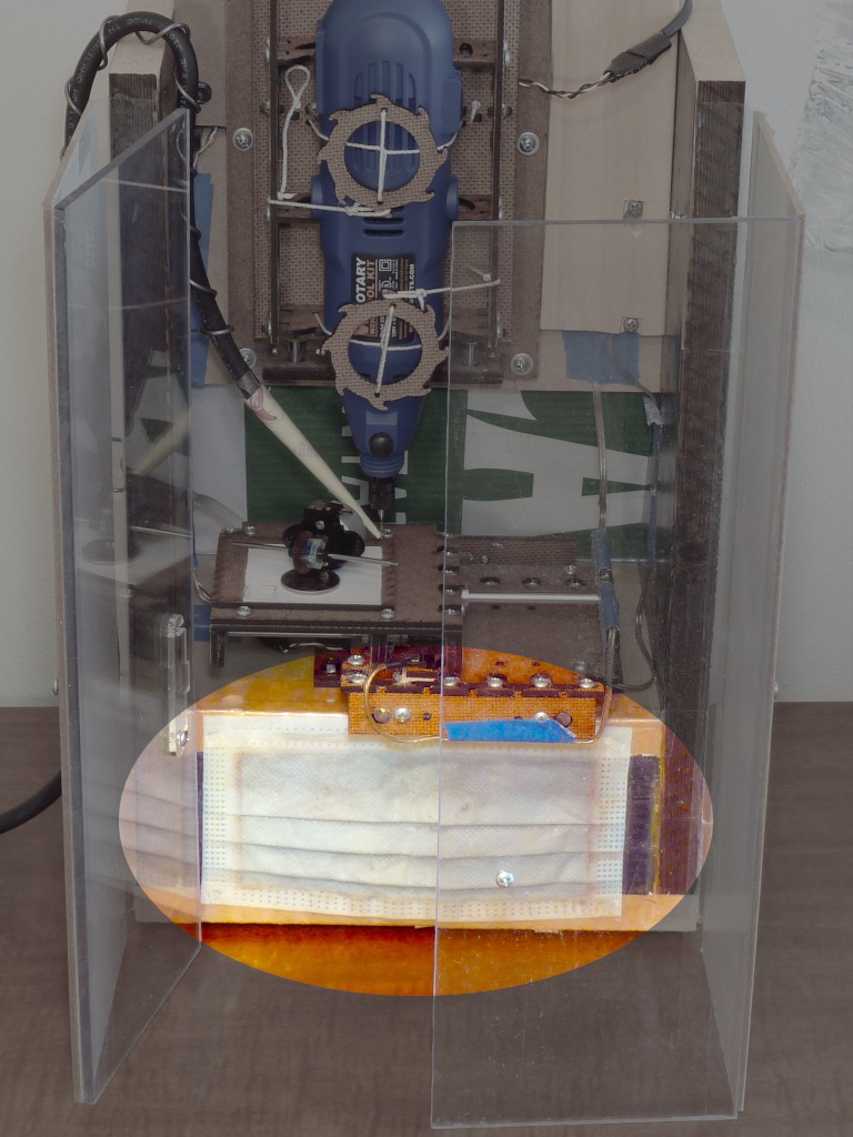
In the first semi-enclosed frame I knocked together, sucking air down into the enclosure and thru a filter worked well:
![]() Sticking a vacuum hose into the same space would probably work too -- to the extent that a given vacuum's filtration works -- but I'm going with running a vac briefly to clean up vs. continuously while operating (and I can use a cordless hand vac).
Sticking a vacuum hose into the same space would probably work too -- to the extent that a given vacuum's filtration works -- but I'm going with running a vac briefly to clean up vs. continuously while operating (and I can use a cordless hand vac).
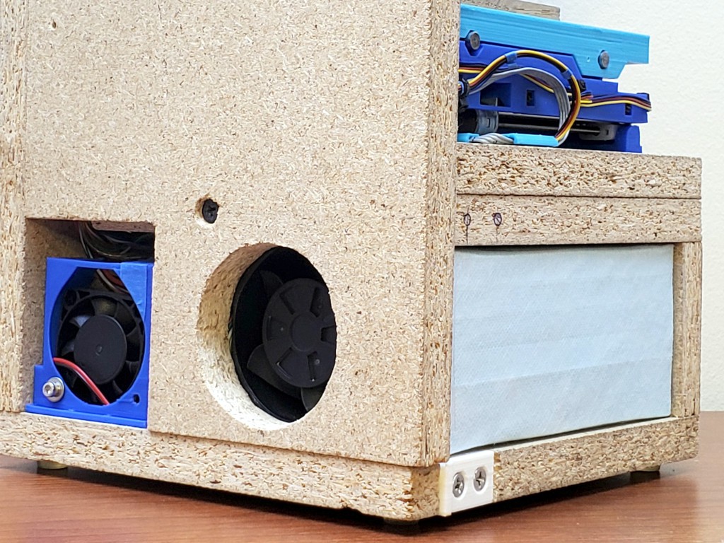
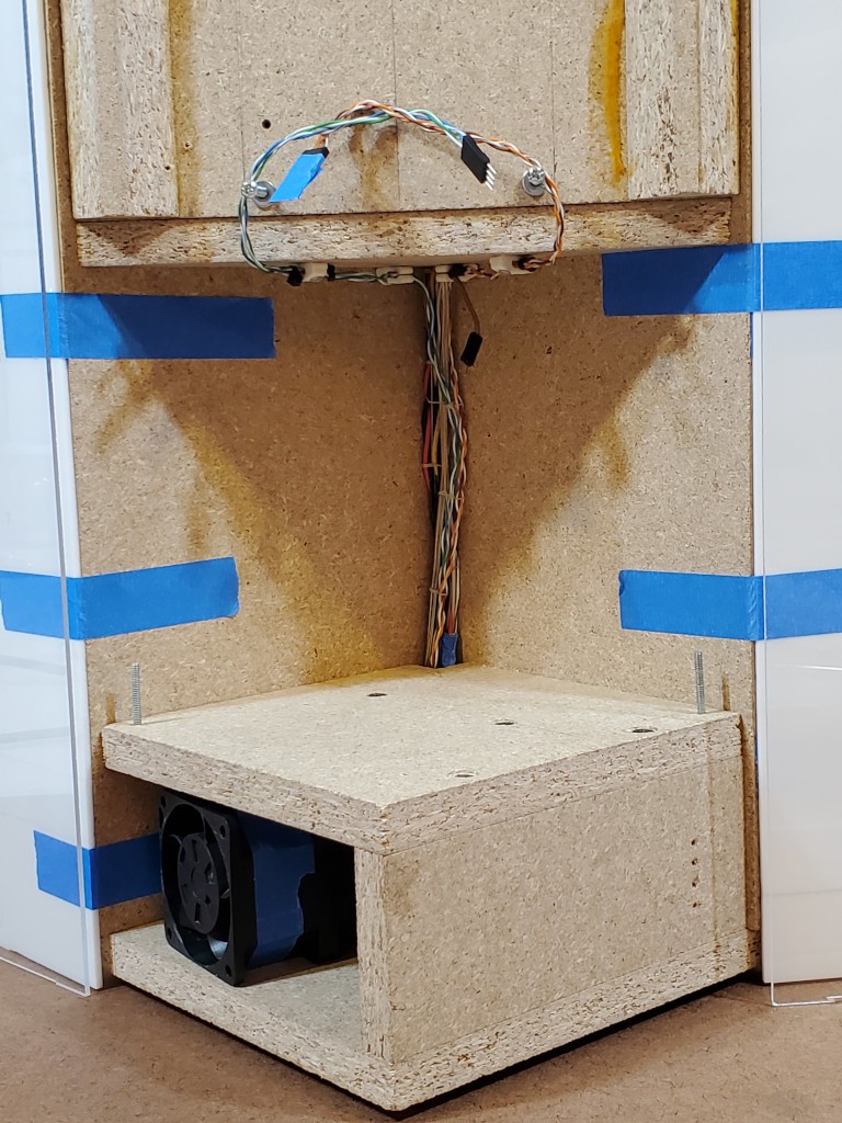
That was good then, then I bumbled into building a new box. The new (i.e. current Apr 2024) box includes space for fan+filter, the fan, and fan power switched by the "coolant" signal. But no filter or exhaust opening.
Lots of photos over the last ~year have shown this thing rattling around loose in that space:
![]()
... and sometimes in the accompanying text I've mumbled about that vent thing that's going to work great just as soon as I get it done.
Now at last ... it is done!
Only took most of a year.
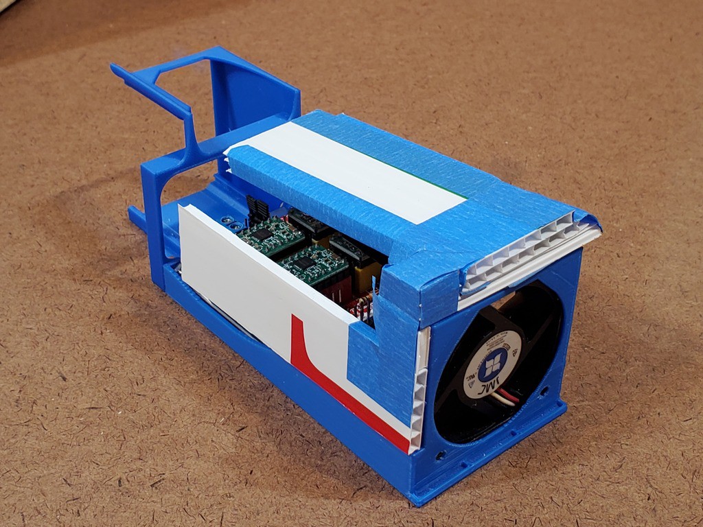
![]()
The idea is to keep dust from floating up out of the enclosure, or filtering out through various gaps, by sucking a sufficient flow of air in, mostly down through the open top.
I could just stick a vacuum hose through the back of the box. But that wouldn't advance the all-in-one idea of this project.
Some of the meanest stuff to spread around would be fine wood dust <citation needed>. Appropriately rated surgical masks <US rating - where did I note that already?> which purportedly can catch >98% of the mean stuff have become much more readily accessible post pandemic. And the planar filters occupy ~no volume. That's great. But they're not very free-flowing, and I want to pull lots of air through one. That's less great. Qualitatively, I figured pulling much air through one of those would require pulling much pressure drop behind the filter i.e. pushing much pressure gain across the fan. At a useful flow rate. That means a) power and b) coupling power to air with suitable pressure/flow characteristics.
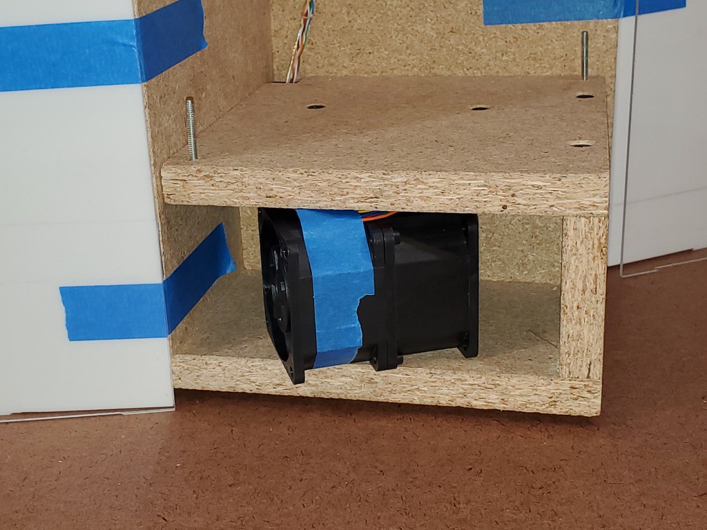
A mean fan
After proving the function of the idea with a pair of mean fans that very much did not fit inside the box, a search for sufficient meanness in a sufficiently small package lead to discovery of "6076"-type integrated counter-rotating fan pairs. While often packaged as quite costly "server" fans (originally developed as such?), they can be had for less from less institutional sources. The one I got is a 12V 3A unit, which seems typical for the type. It does the job. It is not quiet. Random sellers sometimes advertise them as "violent". In free air it's kind of like a ̶l̶i̶g̶h̶t̶airsaber: projecting a tight forceful beam that stays tight and forceful for about a sabre-length. Fun. But I digress.
(further digression: The search for a small mean fan started with the idea of looking for a fan with a stator. That lead to learning about high shear mixing and why those little stick blenders aren't necessarily a joke.)
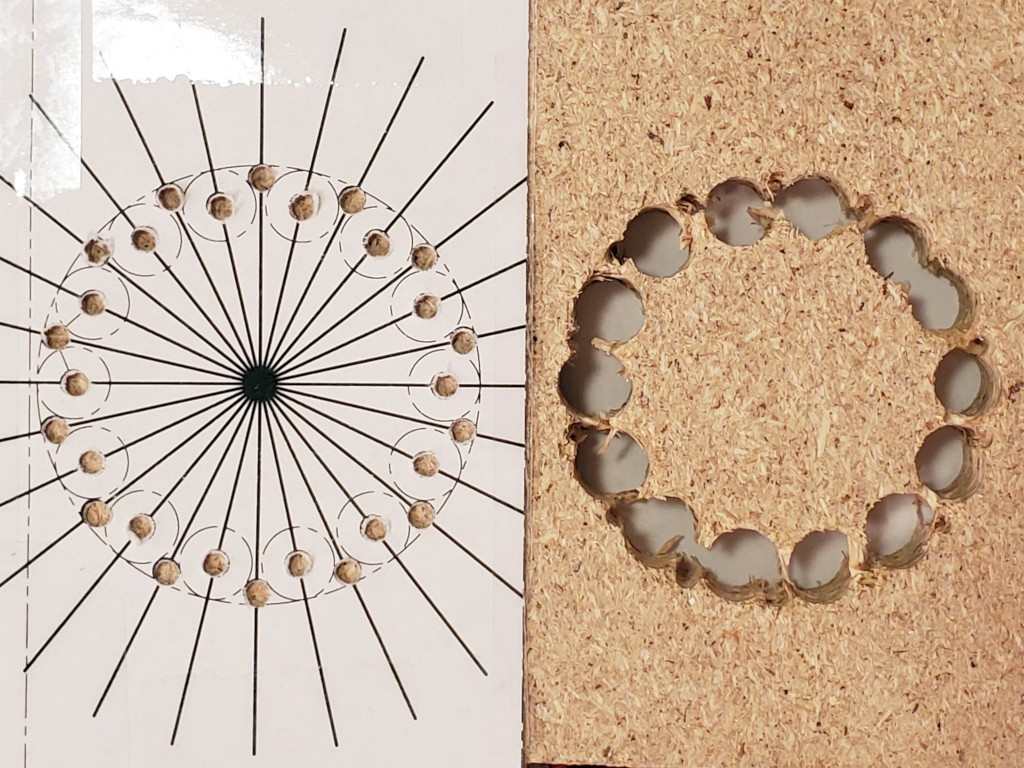
The 60mm dimension of a 6076 fan conveniently fit in the first enclosure, which was a happy accident. Less accidental in the current enclosure.
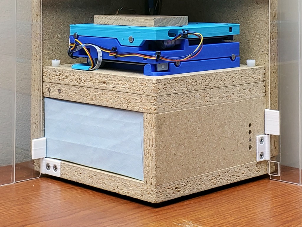
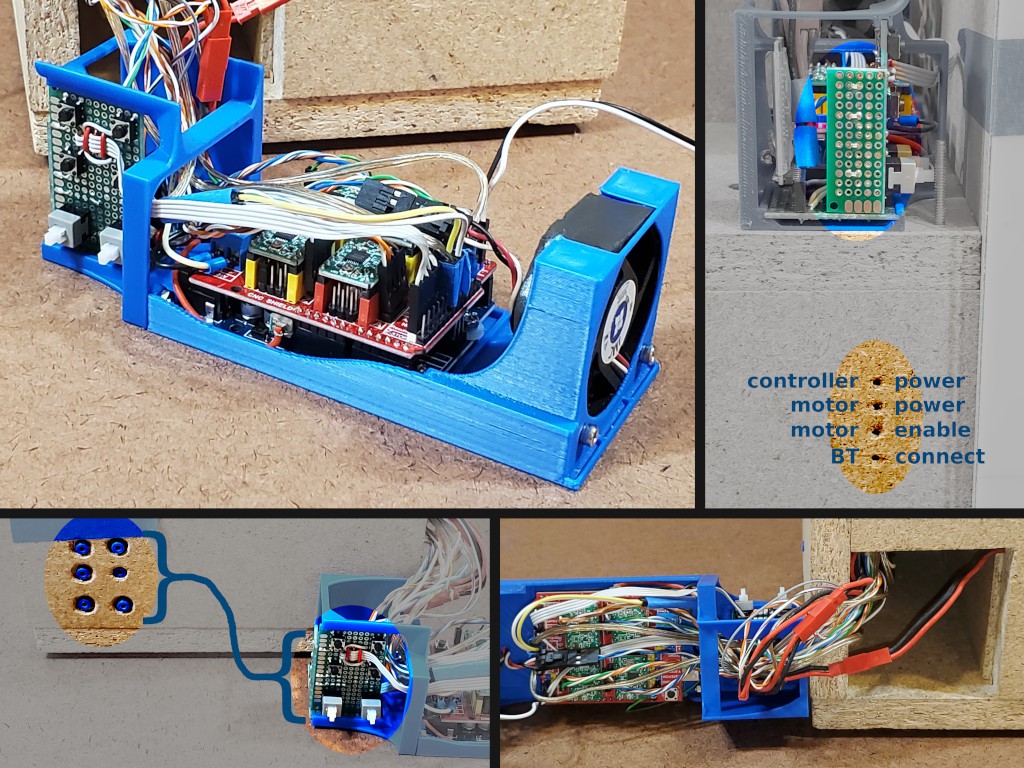
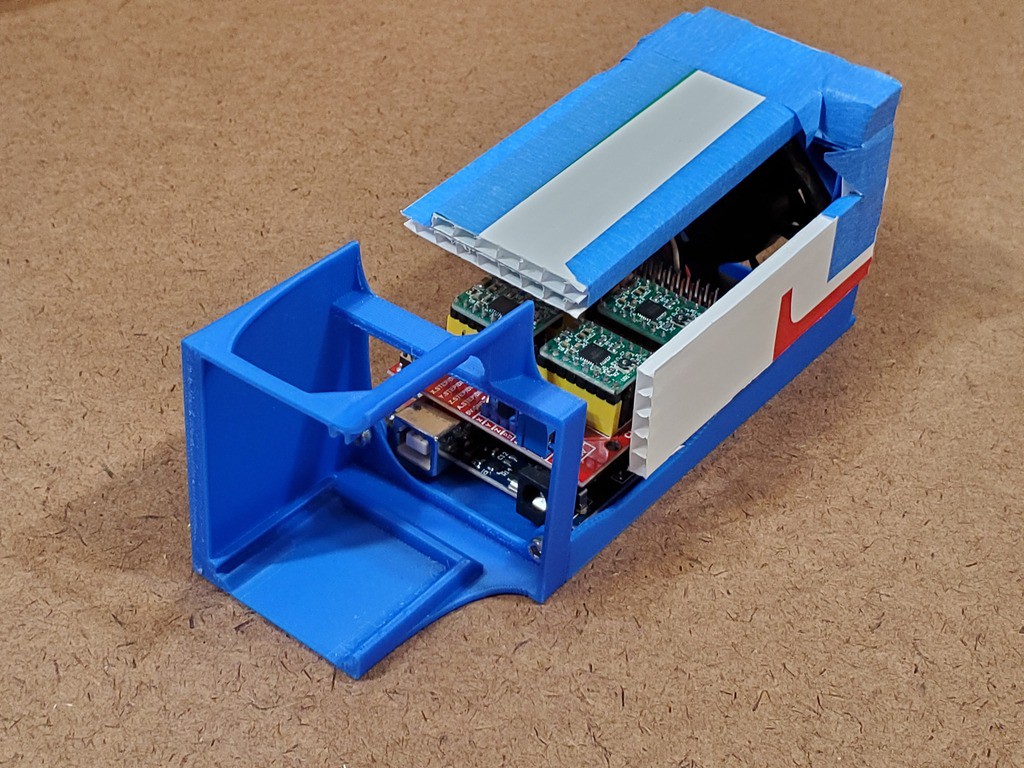
![]()
Nevermind the janky blue thing on the left -- that's the Grbl sled (controller, stepper drivers, Bluetooth, buttons & blinkenlights, &c.) and it needs a do-over.
I probably could have comparison shopped all the hardware stores for a hole saw, gone back for the winner, got home, and made a hole in the time I burned making the hole for the fan exhaust.
![]()
This fan is by far the largest DC load in the box, so it drives power supply selection. It's switched by the "coolant" signal.
![]()
The next evolution I have in mind is to make some mechanical filter grip to make changing filters easier. And to make that grip thing hold pleats for more surface area.
-
chip blower
04/16/2024 at 01:18 • 0 commentsLots of catch-up logging... this was ~10 months ago...
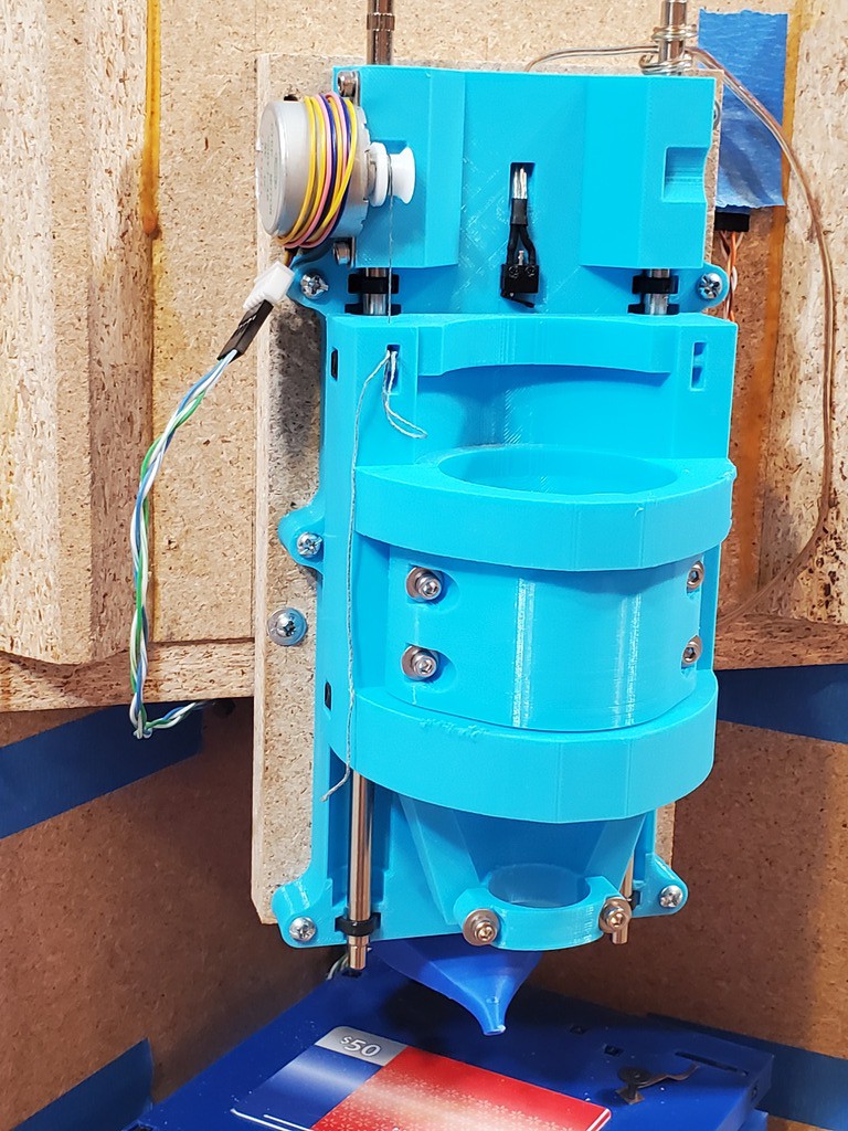
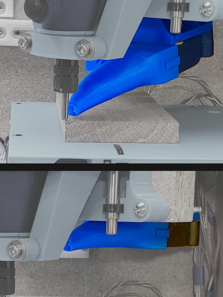
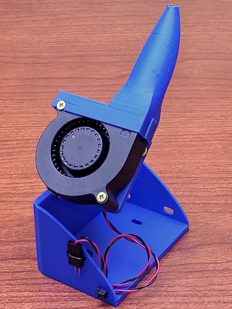
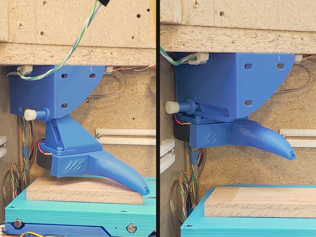
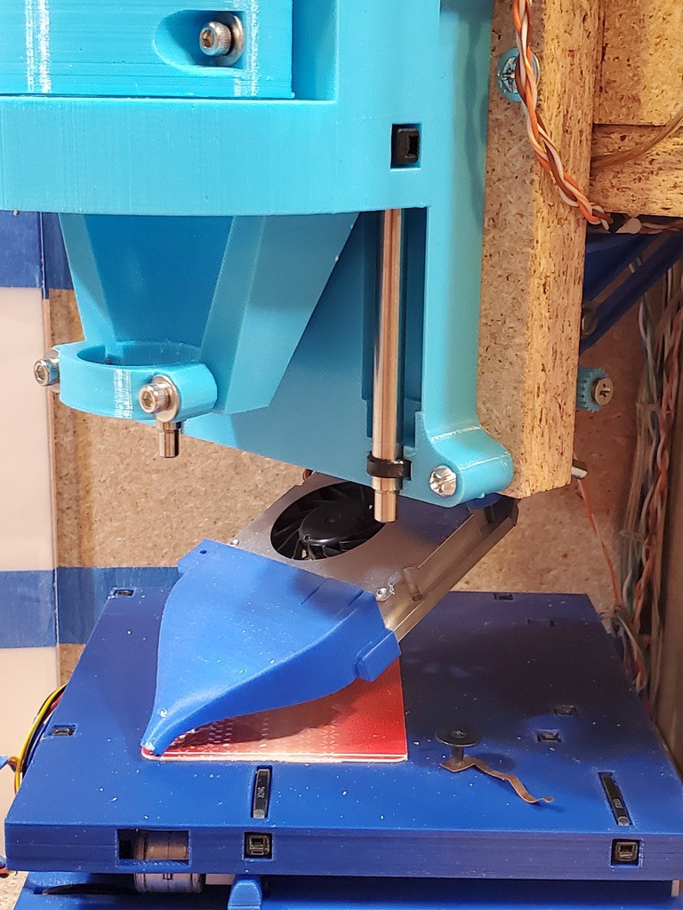
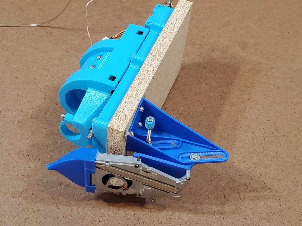
Earlier iterations got useful results from directing meager airflow through a tight nozzle right up close to the work, so this iteration started with that premise. The blower nozzle is adjustable to get right up to the tool and top surface of the material, or far out of the way.
![]()
This blower blows enough air that it doesn't have to be quite so tight to the work, so maybe the next rev will lose the wraparoundiness from the nozzle tip. That didn't print very well in this instance anyhow.
---------- more ----------
This version steps up from a scrapped laptop exhaust blower (centrifugal fan) to a "5010" blower. I splurged a few $ to buy one from a reputable source with datasheets so I could select for high static pressure over free air flow, supposing (based on no real information) that would get the most blow through the constricted nozzle.
![]()
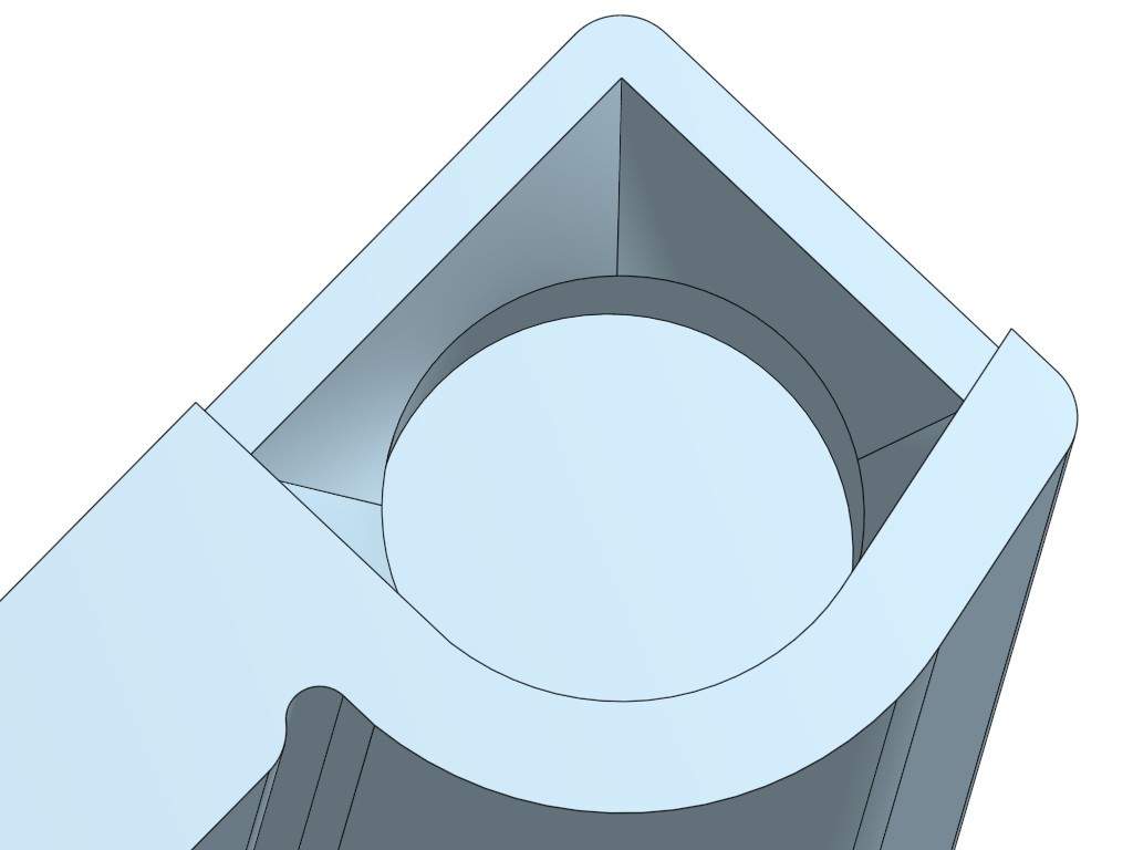
The nozzle starts with a ~constant-area transition from the rectangular fan outlet to an ellipse of the same height, then follows a curving taper to the circular exit. The rectangle-ellipse transition looks unlike constant area from the outside because wall thickness thins in the same span.
![]()
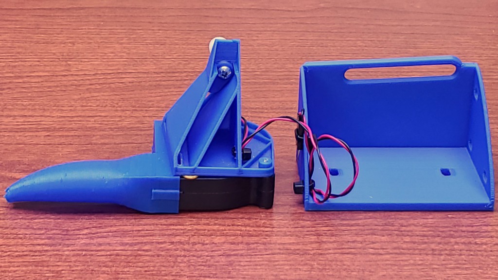
The single point screw clamp through two crossing slots easily holds the very light fan+nozzle with light fingertip torque on the thumb nut. A spacer holds the nut out where it's easier to reach behind the Z axis.
The fixed bracket has mounting holes (short L-R adjustment slots) on two surfaces. The front surface mounting holes are a legacy of earlier iterations on this theme which were screwed to the back of the Z axis because I thought that would be easier than trying to get a screwdriver under the bottom of the top part of the frame. From experience handling that, I figured making the detached Z axis less awkward to handle be worth another think about how to attach the blower to the frame instead. This time a couple of screws down through the frame gusset from above make studs projecting down from the bottom of the top part of the frame and thumb nuts fix the fixed bracket in place.
![]()
Power for the blower is switched through a transistor by the SPINdle ENable signal so it runs together with the spindle, unless prevented by a manual blower defeat switch.
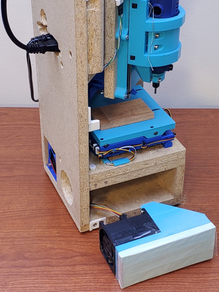
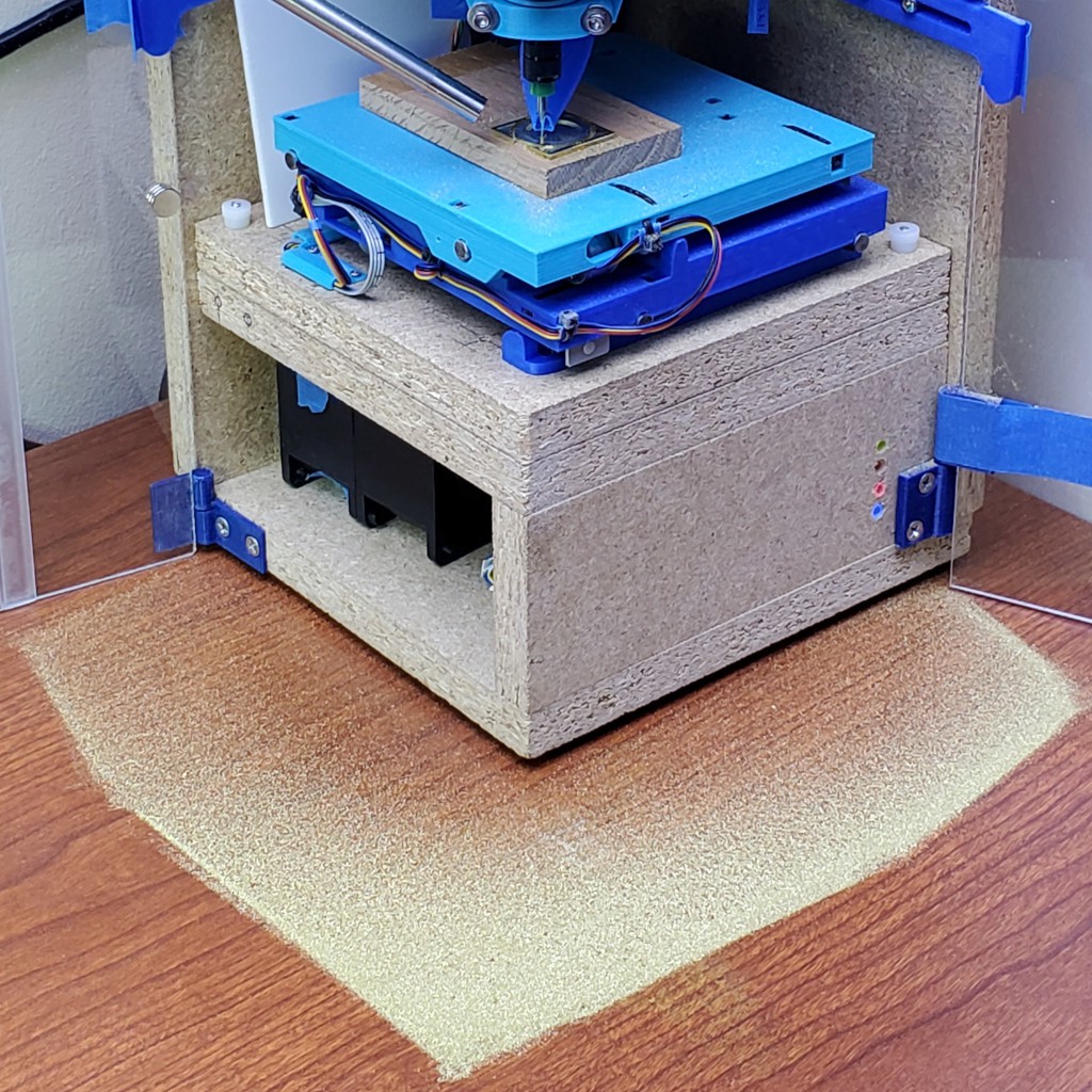
The blower works well.
![]()
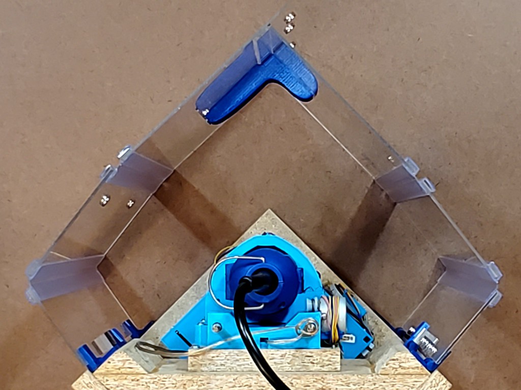
It blows chips out the open corner of the frame to be captured by the surrounding enclosure where they can be vacuumed up after a job finishes.
![]()
-
doors: done. for now. maybe.
04/15/2024 at 01:17 • 0 commentsThis doors thing has been going on for a while. I think the latest try is at least good enough to stop thinking about for a while.
![]()
the main things
- "real" hinges that are not bulky
- long sides held flat without loose parts or awkward closure
- other bits done better
"real" hinges that are not bulky
Early iterations used clear packing tape for hinges. That makes nearly perfect hinges.
but...
---------- more ----------Packing tape, especially the adhesive, doesn't last forever, especially when exposed to light. And it's not really "real" from a product design/manufacturing perspective. Why do I care about "real"? I'm not planning to get into manufacturing or long-term product support, but as I was continuing to spend time on this idea it seemed less attractive to commit so hard to a design element that could never be made "real". That, and some conversation at MRRF last year. After looking at a bunch of worse options, I tried a "living hinge" extrusion. That was "real" but really bulky and much less nearly perfect. Meh. Then I found some coextruded acrylic+flexure hinge that is "real" and not bulky.

bottom: tape; middle: bulky extrusion; top: bulkless coextrusion And the not-bulky hinge was also close to the same thickness as the ~2mm acrylic I've used for recent iterations. And I've read that near-perfect butt joints can be made between acrylic sheets with the right chemistry. For this build I taped the butt joints, but they could be real...
![]()
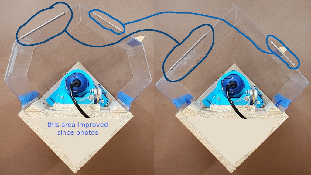
These hinges can fold 180° flat, but leaving them for long periods like that seems like it would be hard on the material -- especially if the outside of that fold is an edge exposed to abuse. So I kept the overlapping 90° folds around the corner as adopted for the bulky hinges instead of going back to the 180° flat folds on each side like what I took to MRRF last year.
(I haven't re-found where I got the tape-hinge idea, but did find that RC foamy plane builders use various kinds of tape for hinges in a similar way.)
that's great. but...
The coextruded hinges are unobtainium at retail. And I don't want to dox my source.
so...
Having thus determined that "real" no-bulk hinges are possible, I'll probably go back to tape for future iterations. Maybe there are tape options that could pass for "real". UV resistant? There is "hinge tape" for books, etc, which might work, but this isn't quite exactly the same as taping up a library book. ?.
long sides held flat(-ish) without loose parts or awkward closure
In this corner-oriented version of the frame, the doors fold up compactly for storage by folding where they're not supposed to fold in operation. Then they're supposed to not fold (much) where they're not supposed to fold in operation. This seems to work ok:
![]()
For a first try I made some metal clips that slide along the top edges of the doors to lock out the "wrong" joint.
![]()
enclosure shape matters to keep clear of projecting horizontal axes That kinda worked, but:
- separate parts = lost parts
- (some variation of pin-in-slot might have worked but didn't have any great idea how to make that simple)
- changing from 180° to 90° folds for storage (because bulky hinges) would have put one of those on the outside where it would be vulnerable
When the sides are straight, the two doors meet at a perpendicular corner. Instead of enforcing straight sides, I also considered enforcing perpendicularity where the two doors meet, which would force the sides straight (if the short sides were held out straight from the frame sides). Using a closure that could attach only to the outside surfaces of the doors because of how the doors fold closed. I had an idea for that sketched that I think would have been not too complicated to make, but didn't get that done before changing how the doors fold.
Changing to the "real" but bulky hinges changed how the doors fold, which:
- would have made one of the top-edge clips vulnerable on the outside of the closed-up box, and
- allowed closure parts to attach to the inside surfaces of the doors instead of only the outside.
So I changed over to enforcing perpendicularity at the corner with a rigid magnetic closure instead of straightness at the sides.
![]()
nevermind the reflections, here's the L-shaped thing in the corner; the long side w/magnet is longer than it needs to be because dumb modeling mistake; secure magnetic closure is easy -- just use more magnets! When I started remaking the doors this time around I assumed I'd be repeating the ⟂ closure with incremental improvement. While having a little rethink before actually cutting stuff, and thinking I could do something on the inside of one door but only one, some recognition filtered through my head that it wouldn't be unthinkably horrible to cut down part of one of the doors a little to expose the inner side of the other/outer door when closed up for storage. Then I could do something about locking out the "wrong" hinge from the inside. After some hours of leaning on constraint-solving parametric CAD, and cutting the "inside" hinge down more than necessary after cracking it on the first try, this seemed to work ok:
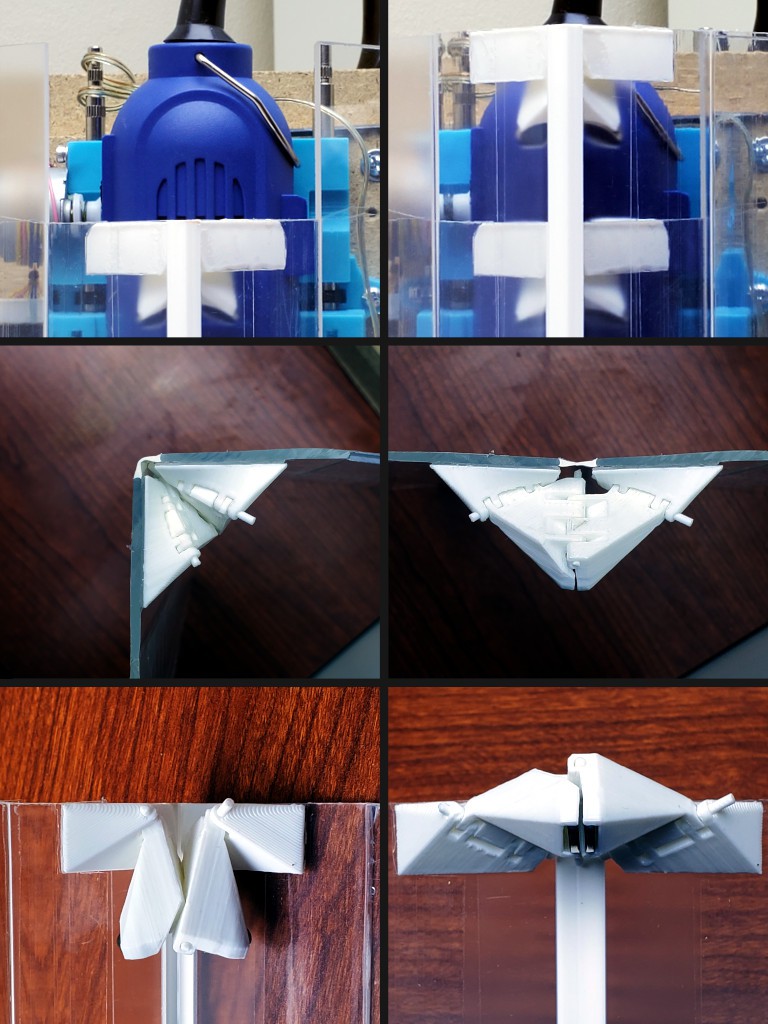
![]()
top: inner & outer hinges nest without interference when closed
mid: hinges lock when opened slightly beyond 180° flat (2nd unit printed overshoots flat at top to counter twist down thin panel)
bottom: magnets self-lock when opened; light bump "breaks" lock to close up for storage
(yes, the hinge pins need trimming -- and maybe a little heat-squish to secure)That holds the long sides of the enclosure straight(ish) without extra loose parts or extra bulk/complexity in the corner closure. Yay. It wasn't the main problem to solve in this iteration (hinge bulk), but I think it seems like a good thing to have these hinges solve themselves when (vocab? "open"/"close" is ambiguous here) deploying the enclosure for operation and require just a bump each when stowing the enclosure for storage, instead of adding bulk and tedium to every open/close of the corner closure while in use.
other bits done better
- magnetic closures greatly simplified for both storage and operation
- better slide-out braces for the short sides (earlier parts designed for similar but different function)
- less bulky but still removable hinges
- lift-off hinges more positively locked in place when closed
a little more about the lift-off hinges
This iteration was mostly driven by the flex hinges between panels.
The hinge between the frame and first door panel was also taped in various ways in iterations until the prior build with the big extruded flex hinges. Then the bigness of the extruded flex hinges gave some "free" thickness to fit a mechanical hinge at the frame. After looking at a bunch of hardware, I modeled and printed some pintle+gudgeon hinges that worked ok, and provided an extremely simple way to remove/install the doors. That was enabled by a stash of short 3mm dowel pins acquired for another project (that may yet turn up in this wee CNC context...), with the downside of adding a specialty part to the BoM mitigated by the relative generality of the pins vs some particular mechanical hinge.
For this iteration, I liked the idea of the lift-off hinges, but didn't have the "free" room for them to be big. So:
- made them thinner - which required thinner walls around the pins than I would have thought prudent, but trial parts seemed ok and finished parts have held up ok so far. The gudgeons are small targets for drop-in fitment, so I tried to finesse the little material there is (~1mm around around the pin less free-fit clearance) so that I can just stab a door into its home corner in the frame and the gudgeon shape will capture the pin as it slides down the corner. It works pretty well and hanging the doors is easy.
![]()
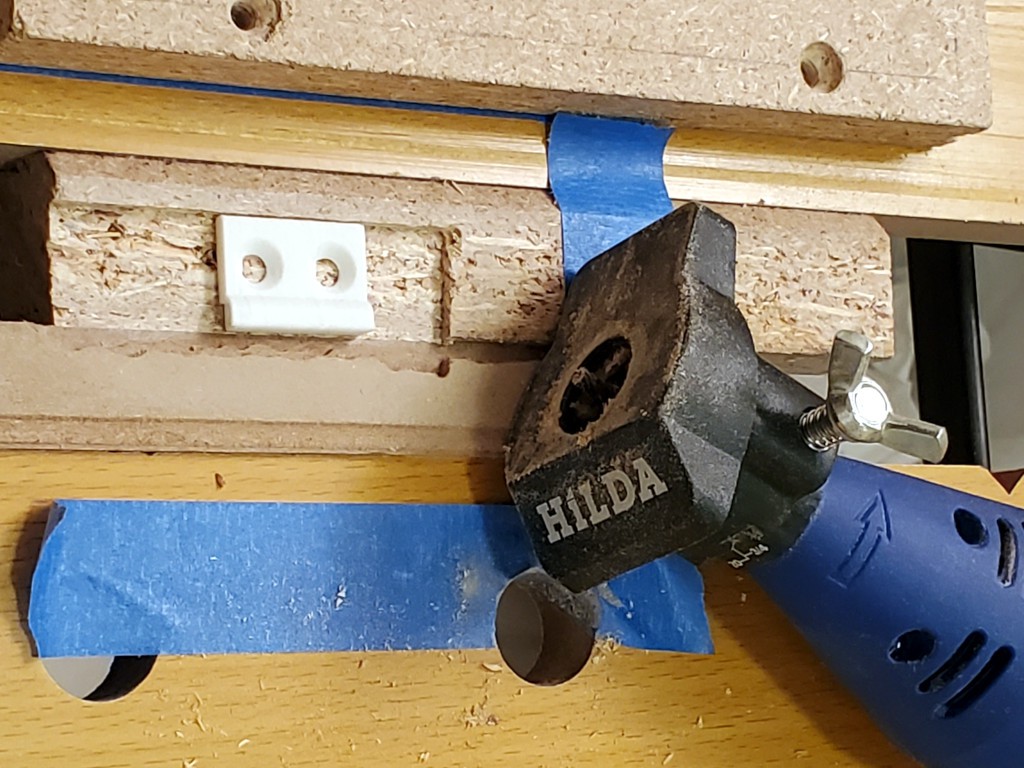
- recessed a couple into the frame (2 of 6) - after hesitating to add complexity and more tools to making a frame/box before remembering that the project intrinsically implies possession of a rotary tool, and I had a very inexpensive & small depth-setting widget:
![]()
-
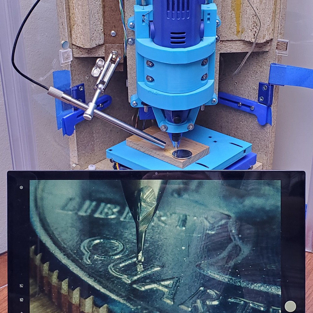
Close-up camera
02/19/2024 at 07:25 • 0 comments![]()
milling this While cutting little parts with tiny bits, it's hard to see/photograph what's really happening from outside the enclosure. Running with the enclosure open isn't my favorite thing. Some macro camera options look like they might fit but awkwardly at best. And cost.
This looks like it should work:
![]()
close up view from far away -- retire the safety squints ---------- more ----------
That's a "USB Digital Microscope, Teslong 10X to 200X Magnification Camera with Stand, Portable Handheld Electronic Coin Magnifier, Soldering Camera Ear Otoscope", as currently listed on Amazon (meh: price up since I bought last October (yes - it's been parked and burning a hole in my to-do anxieties for four months)).
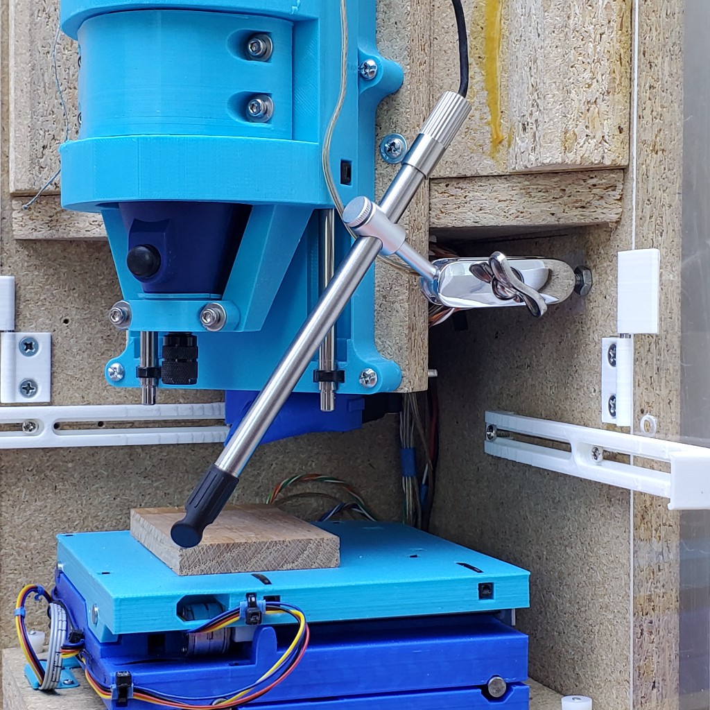
![]()
seller's pic The jointed arm comprises a double-ended clamp and two 10mm balls. The base appears to be molded as a unit so that ball stays there. Since my people revere a tradition of eclectic units, we keep no metric size threaded balls in this land. However, we also revere a tradition of securing parts of our ceiling light fixtures with ball cap nuts a little bigger than a barley grain (3/8 inch) and those are close enough to the right size. Barely. But not really. After I got tired of trying to not bump the not-so-tightly clamped arm, I stuck a fiber washer in there too which conforms and gives a better hold.

3/8" ball = ok; 3/8" ball + fiber washer = more ok; 10mm ball wins if you've got on update Apr '24:
At first I thought keeping the camera-stick "out of the way" seemed like a good idea.
Dealing with the large rotation between camera and naked eye views proved harder (slower & more disruptive) than I wanted to deal with. After some fiddling -- the base ball was on a small scrap that I could move around -- I moved the camera mount and added the side-viewing mirror accessory that came with the camera in order to get 1) a camera view less distractingly different from naked eye view, and 2) a camera+mount position inside the closed-up volume of the box so it doesn't have to be completely re-positioned to use the camera or to close up after using the camera.
![]()
-
evolution of doors
02/19/2024 at 07:21 • 0 commentsLast fall (2023) I logged some of this "fancy box" work alongside the 3d printed CNC mechanics work at #Minamil 3dp: another minimal CNC mill while using that as my single "new project" per Hackaday Prize rules.
Logs there describing work that advanced this project here include:
feature creep vol. {n+=1}: doors review of enclosures from zero to the demonstrable but inadequate state that I took to MRRF
(hinged w/packing tape = not really "real")doors again: current and (maybe) future the less inadequate but more unsatisfactory state accomplished for HaD Prize entry
(not hinged w/packing tape, but inelegant)
...and athing I found shortly before publishing that log...There's other stuff from that period that I still haven't written up, like evolution of the AC wiring, chip blower, &c since the previous log entry
(if you've landed in the middle of the story: this project is me making a fancy box that's not at all necessary to make and use CNC mechanics described here if you have a 3d printer or here if you have a laser cutter)
-
closer to all-in-one: first try building in new box
07/25/2023 at 20:38 • 0 commentsEarlier this year..
The CNC mechanics of #Minamil: a minimal CNC mill had been working encouragingly well for a while but depended on a bunch of other stuff that could be integrated into a compact enclosure but wasn't. A few months ago I made a new XY stage with longer leadscrews that couldn't fully extend within the frame/enclosure I was using at that point. In the parallel universe where I have better executive function, I simply put the new CNC mechanics in the old box for initial testing with useful if not maximal X range and -- as it turned out -- more work to get it the new thing working as well as the old thing. Instead I started thinking about a different enclosure and that got out of control for a while before I got back to getting the actual CNC part to work.
![]()
That was a usable first draft and useful for finding pain points to motivate a second try.
Unfinished bits included:
- switched AC for spindle still not inside the box, but at least consolidated to a hacked power bar
- negative ventilation motor wired but filter & outlet not done
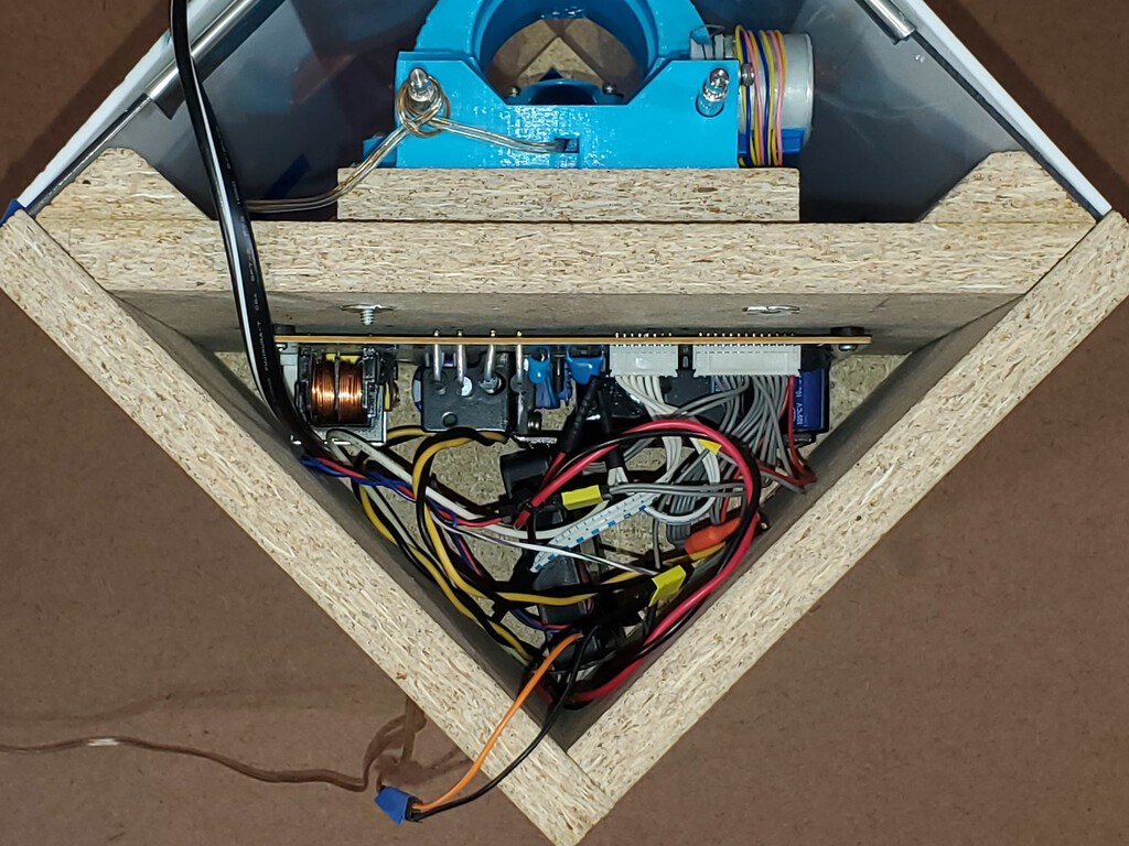
In addition to supporting the CNC parts, the box encloses spaces in the top and bottom. AC power stays isolated in the top part. The bottom part is divided into space for the air filter/fan and space for the control electronics.
A scavenged unenclosed 5V/12V supply with output through PCB headers and lots of little wires doesn't help the top end look any less chaotic inside. At least it keeps AC away from the rest of the works.
I figured everything should fit and I've already learned that wires fill more space in real life than in diagrams, but once again underestimated the challenge of connecting lots of things in a small box.
Doing this once spawned ideas for how to do essentially all of it differently. I really super very much wanted to do a completely new build that I thought some people might appreciate at MRRF this year -- with fairly specific plans and seemingly adequate time. But life. So less time. So when I did get some time I spent it furiously scrambling to finish just a few betterments before MRRF instead of writing log entries. At least I took some pictures while tearing down the "first draft". Then MRRF. Then more life. RIght now I have some time, and a backlog of ideas. But with this year's HaD Prize "Gearing Up" challenge on, it's time to squeeze in some writing too...
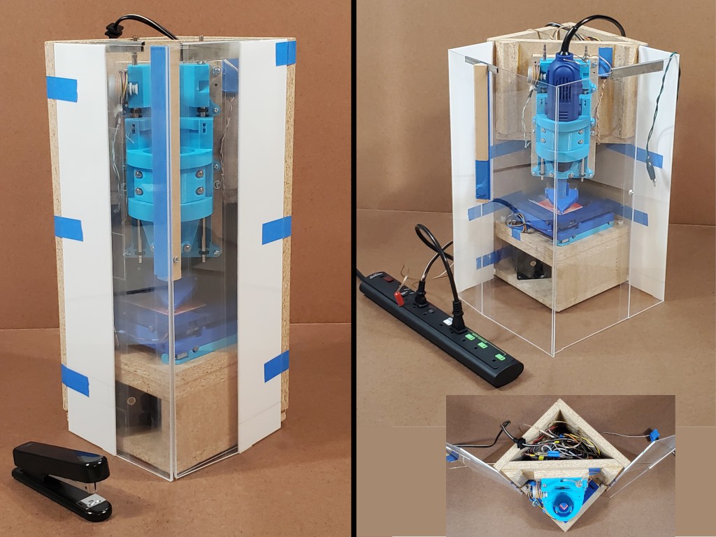
New box, and first try at getting more stuff inside the box![]()
yes, the picture is a repeat -- because a bunch of words got in here after the first instance.
Part of the main idea is for the closed box to be just another box and trivial to stash away wherever without snagging or squishing vulnerable bits.
With the box closed up, I want four flat sides like a plain box with no projections. No hinges, no latches, no buttons, etc. And I want it to be not fragile. In this iteration, moving the hinges away from the corners makes those two corners not fragile. Also the corner where the doors meet is not fragile in compression because the solid panel of each door transfers the load straight into solid material at the hinged corners. For a quickie solution in this case, a single magnet and iron peg (i.e. screw) hold the doors closed, but I have ([1]had?) a plan for a more robust closure. The block in the corner where the doors meet I cut wrong. The idea was to have a single solid piece with the bottom end aligned to rest on top of solid material next to the XY table and the top end in the plane of the top of the box so that, along with the two solid sides of the square, the top can bear load if whatever lands on top has a flat bottom.
Also I have ([1]had?) a plan to replace the metal top clips that hold the straight sides straight when "open" with a closure for the enclosure that would hold the two panels perpendicular where they meet when functioning as a enclosure for the running machine. That's a little tricky because stuff can attach to those panels only on the outside (the sides that face outward in the "open" but "closed" configuration -- err, top-right in the montage above :-/ ).
I really like how this arrangement (and modestly improved next rev) closes up into a very solid box of flat sides ( ̶ ̶i̶n̶s̶e̶r̶t̶ ̶ imagine gif of me vigorously bashing the fragile-looking corner where the doors meet), but it's not clear that clear packing tape hinges can really be a thing (you know that box that's sat by a sunny window for a couple of years...) and I haven't yet found a more respectable hinge with similar function. So this might fade into something sadly less elegant. (...accidental segue to footnote...)
[1] But I might change how the doors fold which would change how the closure works, which would make that idea obsolete. So maybe not building that will be the answer anyhow.
![]()
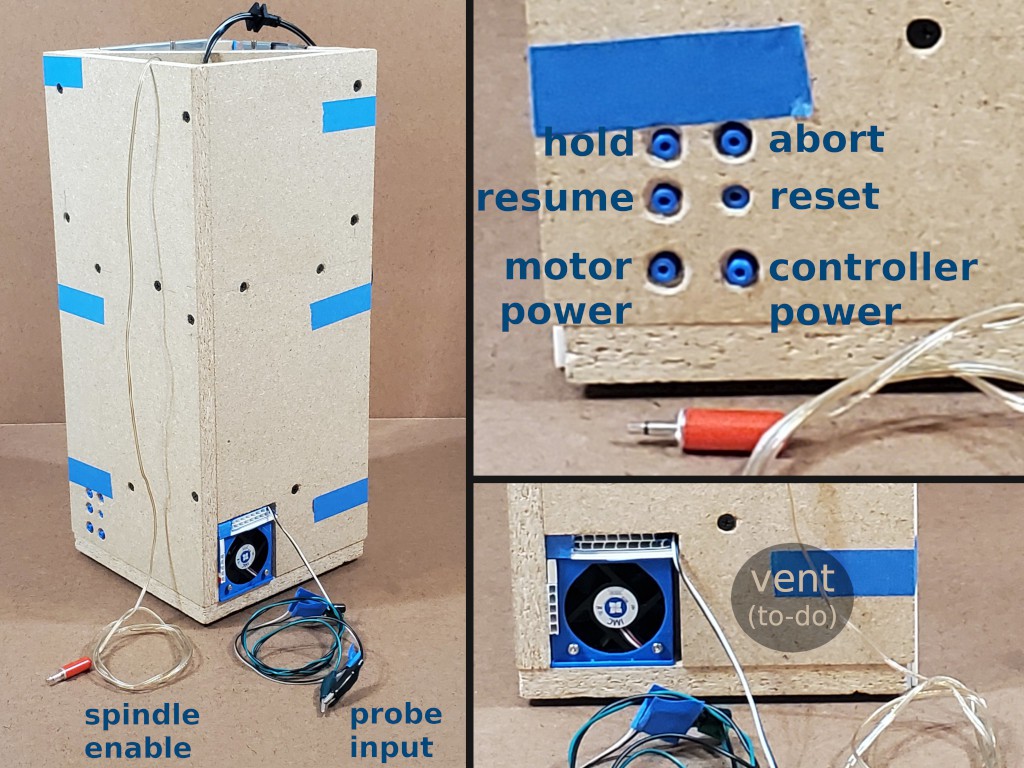
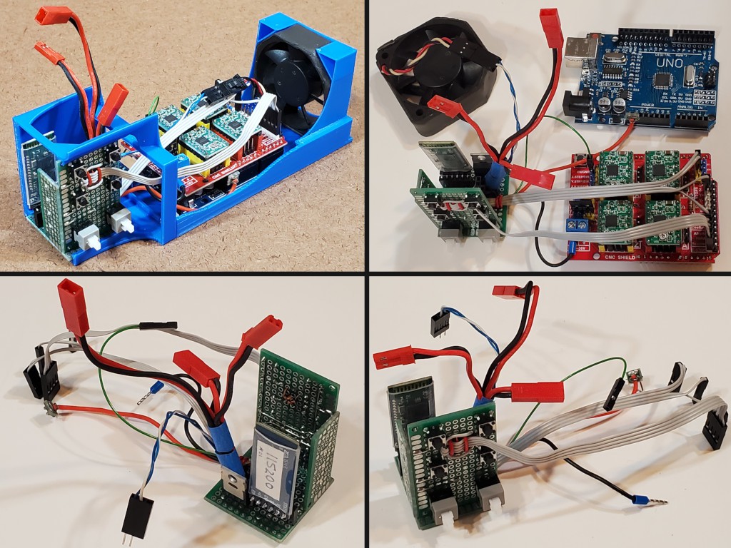
The control electronics all live on a long "sled" that slides in from the back. The blue square with the fan. Status LEDs show through the front. Electronic switches on the sled line up with captive mechanical pushbuttons in the side panel. More pix below.
The control buttons, including push-on-push-off switches, are (supposed to be) slightly below flush with the panel side when "out" and surrounded by fingertip-size relief to allow pressing them "in". Except for reset which is shorter with less relief around so that it requires more deliberate effort to press.
They are out of sight but easy to reach (assuming operation with the solid walls to the right and back and the enclosure panels to the left and front). The hold and resume buttons are at the heights of index and middle fingers for a standard hand (i.e. mine) resting on the table.
"Plans" include adding more tactile cues to help fingers find the buttons quickly. Mainly to confidently distinguish the hold/resume/motors column from the abort/reset/controller column without feeling around. Another idea was to make a removable oversize cap for the abort button to hit with a blind slap then remove and stash in the box when not in use. That might work as the 'tactile cue' if not too sensitive to off-axis touch by a finger sliding along the panel surface.
This arrangement might turn into just a bigger hole in the side panel to expose a solid control panel on the sled. Reasons for not doing that in the first place have faded.
Probe input wires hang out the back because I forgot to decide where to put an accessible connector in the front. Probably because I had "3.5mm jack" stuck in mind and I'm out of panel mount 3.5mm jacks. Meh.
Top: AC / high voltage stuff![]()
I haven't measured current draw for the CNC electronics and (very small) steppers, but I think it's well under 1A. The main DC load is the big fan to suck lots of air through a non-H(igh)E(fficiency)PA filter. That's labeled 3A, but I measured ~1.5A running. Spin-up, although slow, is still faster than the meter I was using so I won't bet that it's any less than 3A. Plus a couple of smaller fans (chip blower & confined electronics). DC draw in steady state might be as small as ~2A. Considering low precision guesses and fudge factors, call it 3-4A. And power supplies that don't specify "yes, Virginia, this really will put out {x}A forever even in a stuffy box" probably won't. That got me to looking at 5A (60W) supplies and up, which looked like I should expect to put a "real" supply in this space rather than a barrel jack.
For a first whack, I found a 5(ish)V+12V power supply from a dead TV that fit.
I want to keep this space isolated from the work area so no vents in the bottom or "front" (diagonal) faces. I didn't know yet how I was going to do the spindle AC stuff or wire a more permanent DC supply that probably would end up needed switched AC (this one has standby 5V and an 'enable' input so I could get this far without an AC switch) so I didn't want to perforate the other two sides yet either. Sticking a power supply down in the bottom of a deep hole seemed a bit rude. So there's another 12V tap and a little fan down there to stir air and make me feel better. I haven't finished the air filter yet so the big fan remains idle and this supply probably never made noticeable heat anyhow.
The spindle enable signal runs up here from the controller below and there's a 12V tap for a relay. But I didn't get that part done. Instead the dangling wire combines the enable signal and ground from the relay supply to drive a hacked power strip for a half-way solution. The power strip has screw keyholes and I could have stuck it to the back of the box if I had reason to carry it anywhere at the time.
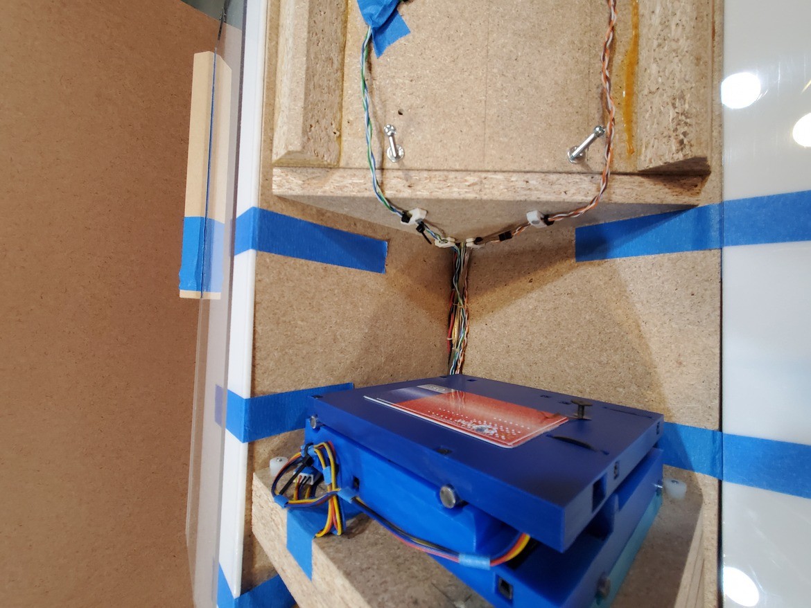
Supply and signal wires drop through a small hole (mostly full of wires, not a vent, and ideally would have some gap fill around the wires) in the corner and run in a tight bundle (an overwrought experiment in flat lacing -- would have been better if I'd read up) down the corner of the box through the messy place to the electronics in the lower compartment.
Another look at what was in the top compartment:
![]()
This part was all very "first draft" and already gone. But that's another log.
Laced bundle:
- down: 5V/Com, 12V motor supply, separate 12V/Com for the big fan
- up: power enable (12V & more 5V), spindle enable
That bundle runs straight down the back corner of the work area to the Grbl sled below:
![]()
(shown with Z axis wiring also)
Bottom: DC / low voltage stuff
aka Grbl sled
So, the supply wire bundle comes down from the top to this "sled" that slides into a pocket in the base of the box. Status LEDs line up with holes in the front and switches on the side line up with captive buttons in the side of the box.
And a bunch more wires go back up through the same hole into the work area above. Except power for the big fan which goes over to the other side of the box base.
![]()
Push-on-push-off switches:
- 5V to controller (Grbl on Uno clone + Protoneer-designed CNC shield + A4988s)
- 12V enable signal to power supply
When the supply is not "enable"d, standby 5V (>6V open circuit - which exceeds "absolute maximum" for the mcu so minus a diode drop) provides enough juice to keep the controller & bluetooth alive. Barely. That load drags the voltage down to I forget what but well under 5V (before add'l diode drop). Setting the "enable" signal to the PS lights up 12V and solid 5V.
The compartment gets really crowded with wires:
- bundle from the top compartment
- switched 5V to controller
- 4x 4p stepper cables (support for redundant Z motor)
- 3x 2p limit switches
- 2p switched chip blower far
- spindle (& chip blower) enable
- fat 2p switched vent fan
- vent fan enable
- 2p sled fan
- TX/RX to BT module
- motor enable to status LED
- 4x tact switch (hold/resume/abort/reset)
- ground to CNC shield (also grounds controller)
Part of making all that fit was running all wires that leave the compartment up to the front of the sled. From there all the wires run in a somewhat parallel bundle about the same distance back to where they go up (or sideways) out of the compartment. Then when the sled is in place there isn't a lot of extra wire in where there's no extra room, and that length of wire allows the sled to be pulled out without disconnecting anything.
Another part of making stuff fit was concentrating the off-controller stuff -- LEDs, switches, fan FETs, BT module, etc -- in a single compact unit with no bulky wire terminals, few 0.1" headers, and lots of short pigtails. Three chips of FR4 perf board hold switches on the side, LEDs to the front and everything else (fan FETs, a few interconnect headers, and lots of interconnect pigtails) on the bottom. Through-hole switches and big FET for the big fan; otherwise SOT-23 and 0603 SMD.
![]()
Yeah, that, and ...
I want to get more pictures in here since they're what's left of that build but I need to get past this log entry which means fewer words. Which probably will mean more future forgetting what was what and why. Meh.
Fans
- upper/AC/power supply compartment -- described above.
- sled compartment
- dust suction (switched as "coolant")
- chip blower (switched with spindle)
The sled has a fan. The controller probably doesn't make much heat and the motor current is small so maybe this doesn't matter. But it's a crowded confined space. So a fan makes me feel better.
This iteration was a ̶c̶o̶p̶ ̶o̶u̶t̶ ̶ experiment to avoid making holes when I don't know what I want to end up with. The fan exhausts air out. The fluted sign board lets makeup air in past the electronics so that it goes back through the electronics on the way out. Hopefully with sufficiently little resistance to avoid sucking cutting dust in through e.g. the LEDs. I tried to see if blocking these inlets reduced airflow out. Inconclusive. Experiment over. The sled wasn't full of dust after as much use as this version got. Next iteration turned the fan around to pressurize the compartment (with clean air) so dust won't (isn't expected to) be a driver of where to put outlets. Or maybe LED & control openings will be enough.
![]()
![]()
This was supposed to be fewer words....
Dust suctionSucking air down into the enclosure and through a filter on the way out worked quite well in earlier builds. ATSM level 2 surgical mask is about the right size and supposed to filter mean micron & sub-micron particles pretty well. But it's far from "High Efficiency". This power-dense counter-rotating fan drives enough static pressure differential to get the job done. It's also crazy loud -- which matters little for an intrinsically loud application.
The fan is wired with plenty of power thru a hefty FET switched by Grbl's "coolant enable" signal. But I haven't made a filter frame or exhaust opening yet. ... must. escape. this. log. first. ....
![]()
Chip blowerBlowing a weak air stream from a weak air pump through a tight nozzle directly at the tool tip worked pretty well in prior builds, but that was one of the worst offenders among things that in principle could be integrated into a compact box but was awkwardly not.
I thought some thoughts about that for a while. So far that's lead to fixing a nozzle directly to a "turbo"-type (side exiting) blower and suspending that assembly on a 2dof rig behind the spindle. Found an old laptop cpu cooler for a first draft.
![]()
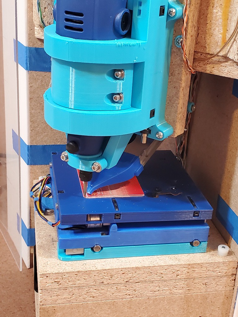
low / thin material:
![]()
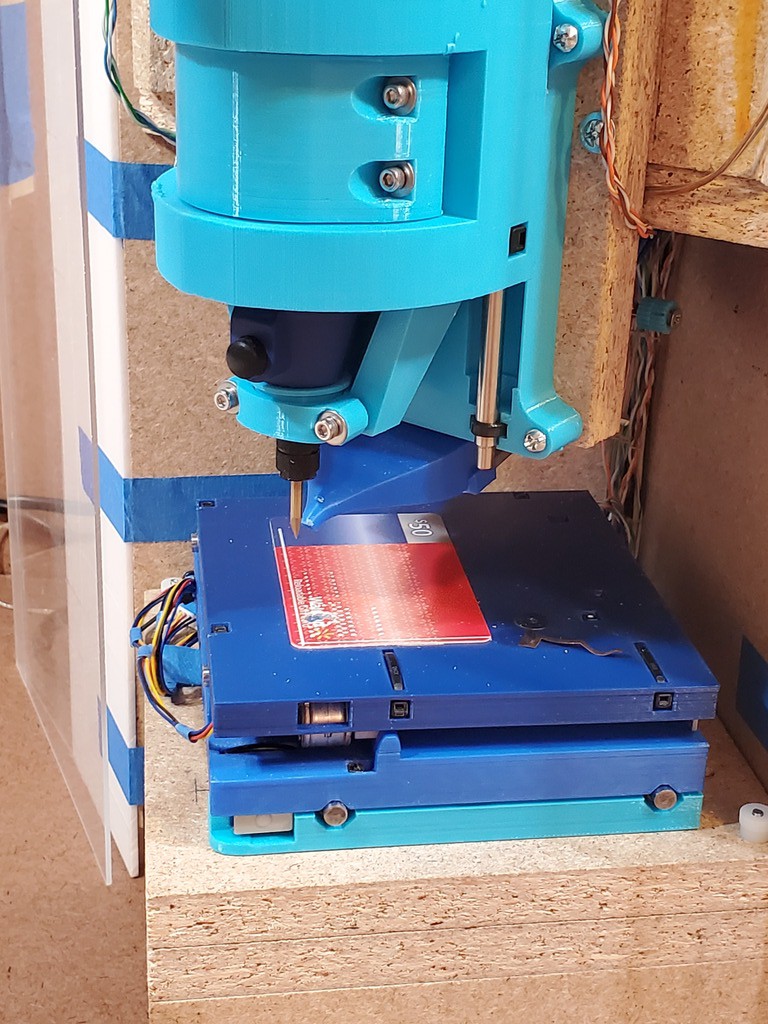
high / thick material (tight to bottom of Z but still reduces Z clearance but still much more Z clearance than thickness of anything I've tried to cut so far):
![]()
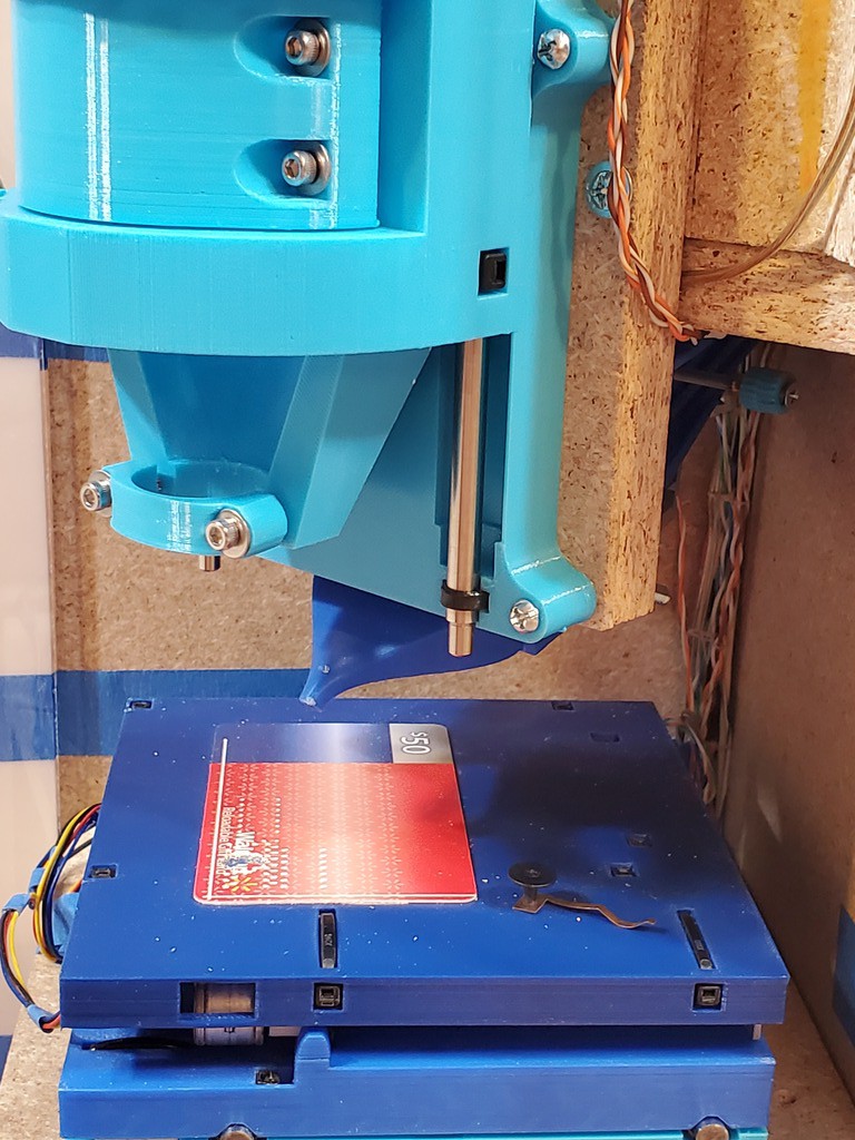
max high/retract:
![]()
the rig:
- hidden vertical-ish slot in moving piece crosses horizontal-ish slot in fixed piece for 2dof
- constraint-solving parametric CAD FTW!
![]()
Hey look... Is that Z axis attached to a removable frame part?
XY axesWhile iterating the axes the mounting screw pattern keeps changing. That means a mess of holes in the prior couple of frames. I've tried to set and keep a uniform pattern, but the uniform pattern keeps changing. Hole entropy only increases.
Also, adding flanges for mounting screws makes the XY table more sprawly, which limits shrinking the overall footprint. Running screws up from below into the bottom of the XY unit would solve that, but no access from below without impractically much dis/reassembly.
Also, I wasn't having great ideas for how to reach the back or right sides with a drill or sensible screwdriver without impractically much dis/reassembly.
Also, I'm more interested in smallness of footprint than shortness of height. So adding ⅝ in. more tallness doesn't break my heart.
So the XY table attaches, from below, to a separate piece of frame material that can be replaced when it gets too perforated...
![]() ...and which is stiff enough to pin down with two thumb nuts in the reachable pair of opposite corners.
...and which is stiff enough to pin down with two thumb nuts in the reachable pair of opposite corners.![]() Actually this "first draft" started with wing nuts instead of thumb nuts. That worked. But they need a lot of room for the wings to swing. This version has the room but I was thinking of a frame shrink before MRRF. When I get to that, it will require something more compact. These thumb nuts are the current candidate for that.
Actually this "first draft" started with wing nuts instead of thumb nuts. That worked. But they need a lot of room for the wings to swing. This version has the room but I was thinking of a frame shrink before MRRF. When I get to that, it will require something more compact. These thumb nuts are the current candidate for that. XY cable dressing remains an unsolved mess in this version. There's no room for excess wire below so excess, and connectors, get tapewadded up on top. Also installing/removing this unit requires hauling out the Grbl sled and fishing wires with big ends made of edges and corners down or up through a crowded hole. Lesson: wires that leave the Grbl gaol have to be disconnectable at both ends. Also lesson: unless they're exactly the right length and can be dis/connected in tight quarters, the XY assembly needs some provision for managing a little extra wire + connectors above the deck but not interfering with motion or limiting footprint shrinkage. As a separate concern, the motor wires come down to the deck at a specific point near the left edge; it would be nice to have a more deterministic fixture there.
The Walmart card is my spoil board for now. It's smaller than the usable work area so that's not a complete solution.
The little spring contact under a shoulder screw helps with Z-probing copper-clad board. The springy part contacts the board and the Z probe -- so far just an alligator clip -- can clip to the shoulder screw.
Z axisThe Z axis attaches to a separate plate also. Along with solving screw hole entropy, this also adds stiffness behind the part of the axis that projects below the fixed upper face of the frame so the printed part doesn't have to handle that by itself. T-nuts in the frame make it easy to zip this on/off with machine screws run into threads that aren't fragile. Also, I cleverly marked out and drilled the screw holes in the frame with just the Z base attached to the detached attachment plate. So there's plenty of clearance around the attached base of the Z axis for the screws that attach the assembly to the frame -- provided no steppers or sliding part of the axis are attached. Besides forgetting about motors, I forgot that the moving part is a little wider than the fixed part. It's just possible to sneak the bottom two screws past the moving/tool-holding part, but the motors completely cover the upper two screws. Bah. For slight relief, I've been running this Z axis mostly with one motor (it suffers less from reasons to want redundancy in earlier versions) so at least one upper screw is easy to use and that's not very much less stiff than with all four screws. So hole entropy in the frame will soon increase anyhow. I've already cut a new (what to call it?) intermediate plate that's a little bigger to spread out the screws a little more.
![]()
I randomly found a box of wire clips at a resale shop that looked like a good candidate for managing the Z axis wiring where it comes to the front from the vertical run back in the corner. Alas, whatever plastic they are made from is crazy stiff and I have to pry them open with a screwdriver to slide wires in/out without scrubbing the insulation -- without crushing wires with the screwdriver that I'm using to avoid crushing them with the clip. :-/
![]()
Attaching the chip blower to the back of the Z axes intermediate board seemed like a good idea at the time. Largely because I didn't want to deal with attaching it to the bottom of the upper compartment of the frame. But it makes the Z assembly much more awkward when off the frame. FITNR.
![]()
Ok, that was kind of a failure to use less words. But instead got done with less photo editing.
"Desk Accessory" CNC Milling Machine
Lots of "Desktop CNC" machines can fit on a desktop. But do they fit _on_your_desk_? Like, between the stapler & paper tray?
 The DC-out cord from the supply could be cut down to the minimum needed to make the connection.
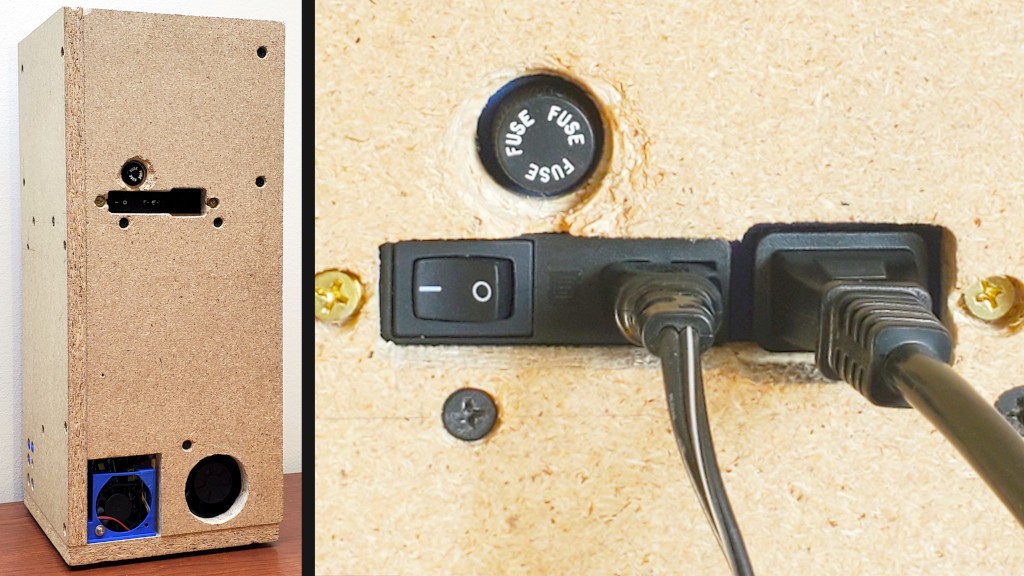
 Sticking a vacuum hose into the same space would probably work too -- to the extent that a given vacuum's filtration works -- but I'm going with running a vac briefly to clean up vs. continuously while operating (and I can use a cordless hand vac).
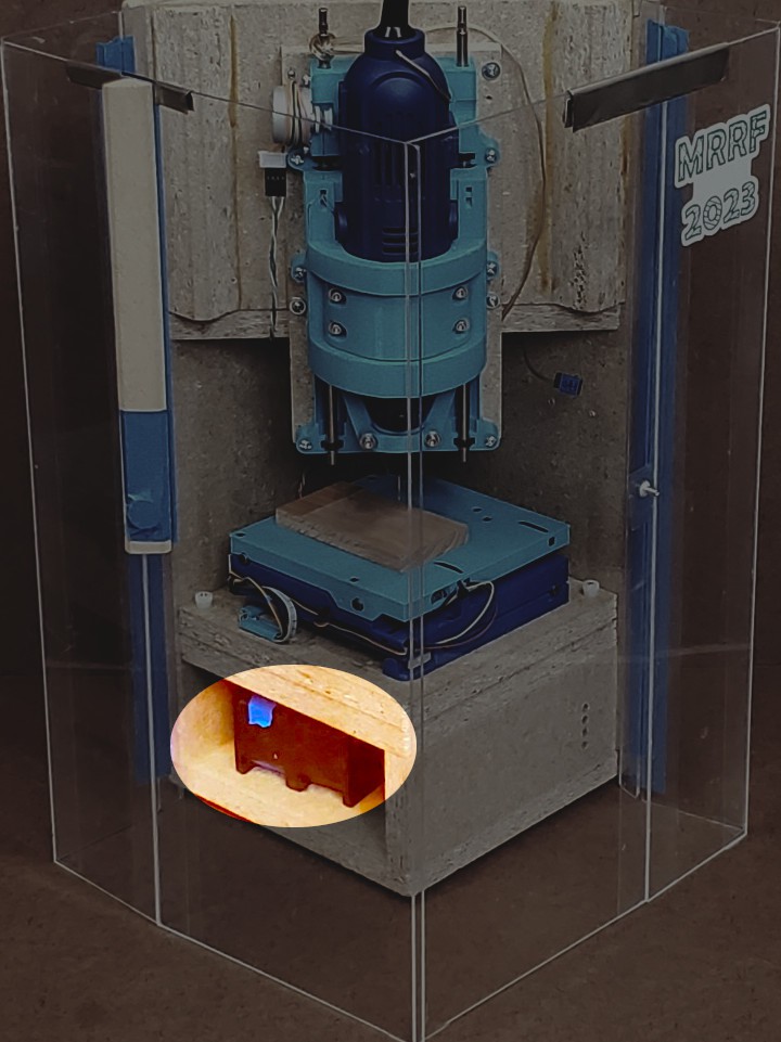


 ...and which is stiff enough to pin down with two thumb nuts in the reachable pair of opposite corners.
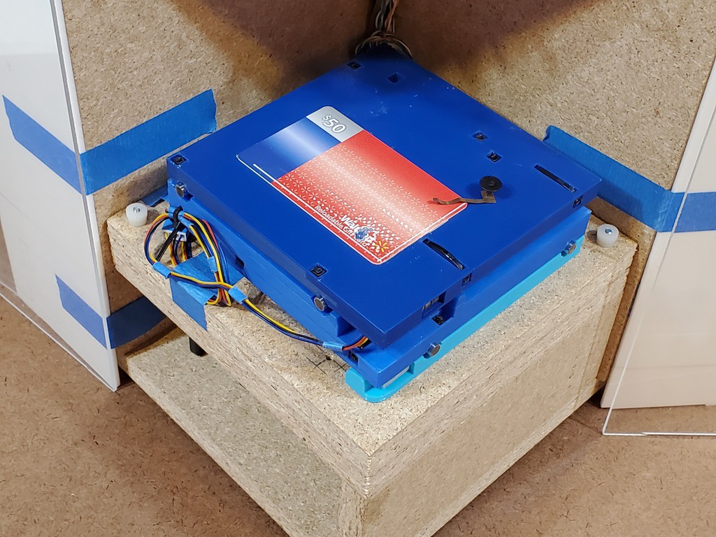 Actually this "first draft" started with wing nuts instead of thumb nuts. That worked. But they need a lot of room for the wings to swing. This version has the room but I was thinking of a frame shrink before MRRF. When I get to that, it will require something more compact. These thumb nuts are the current candidate for that.