In most cases, this hack isn't necessary. But there are two cases where it is. Some washing machines require 240 volt power (if they are a single unit combination washer/dryer, for example). The Intelliflow uses / passes only 120 volt power. The second case is where you want more than one thing to be able to "request" water. In our case, our dryer has a steam function that requires water, so it's not enough for the washer alone to request it (and the washer is electronic, so there's no easy way to just leave it on while the dryer is running).
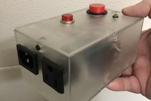
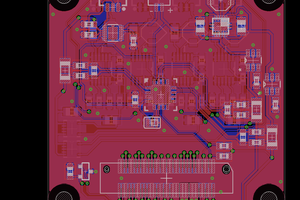
This project is based on Reboot-o-matic and the AC safety timer, but is rather simplified from those projects. There's just a button and a MOSFET switched load. The firmware will set (or reset) a timer for 6 hours whenever the button is pushed. While the timer is running, the MOSFET gate is pulled high, which switches on the power to a bank of 3 27Ω 1W resistors. Those impose a just-under 3 watt load on the power supply (when the load is off the power draw is perhaps 5 mW), which is enough for the Intelliflow to think that the washing machine is running and turn on the water. The Intelliflow is "smart," though, so just a constant load won't do. A real washing machine varies its load pretty frequently depending on what it's doing. We simulate that by turning the load on for 120 seconds every 223 seconds (prime so that it hopefully won't sync with any process going on in the Intelliflow). That's enough to keep the valve triggered. The input power is 5 volts and is supplied by a 5W wall wart that plugs into the Intelliflow's socket. There's a 2 pin connector for a normally open pushbutton (the ATTiny9 has an internal pull-up), and an indicator LED on another GPIO pin (since the load is cycled) to indicate when the water should be on.
Version 1 used an external DC supply, and it does work, but that design results in a more or less permanent vampire load. By doing just a little bit of extra work, we can eliminate that.
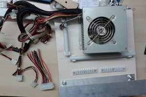
Version 2 starts with AC input on the board. The AC power goes to an AC-DC power supply module, but is switched by a solid-state relay. The SSR's LED is switched on by one of the GPIO pins of the Tiny9. To bootstrap the system, the button is wired across the SSR switching terminals. Pushing the button will turn on the power, and then the controller will activate the SSR and hold the power for the rest of the cycle. Once the cycle is complete, the controller will turn off the SSR and the power will die. The result of this should be a zero load (apart from any SSR leakage) when the system is idle. Version 3 adds a second SSR and moves the load to the AC side. A second SSR is required because the load is cycled on and off throughout the cycle to better simulate an in-use washing machine.
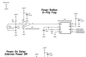
There is one caveat, however. System power won't be applied or removed instantaneously. As the power dies, the operation of the controller will pass through an unreliable stage, which can result in spurious RESETs. Of course, when the controller is reset, the first thing it does is switch the power on. The fix for this is to configure a brownout detector to hold the chip in RESET when the power is lower than a threshold. The Tiny9 includes a VLM - Vcc Level Monitor (why they didn't just call it a brownout detector like every other chip, I don't know), and the software will set it up to hold the chip in RESET as the voltage drops.
Watts actually sells something similar to this project. Unfortunately, their version only turns the water on for 2 hours at a time. I think 6 hours is more reasonable. Even if 2 hours was a reasonable period of time, the extra 4 hours isn't likely to hurt anything, since most machines stay off for days at a time. Also, their version is laughably expensive.
 Nick Sayer
 Christoph


 Pinski1