Wriju
Wriju-
And it ticks! (every 8 seconds)
09/26/2020 at 18:52 • 0 comments![]()
I added a strap and some velcro. I would probably replace it with a NATO strap later. A bit of clear plastic covers the enclosure. It is a bit clumsy because its 10 times the volume and 5 times the weight of my usual Sonata.
I will add some code for visual effects every time it displays a number.
Currently it consumes 1 microamps of current when idle. This reading is correct only up to one decimal place. I measured it with a DT830.
At this rate of consumption, it should last at least a year on this CR2032 coin cell which is rated for 200 mAh but realistically probably would provide only a 100 mAh.
I am only a beginner in electronics and this is not my comfort zone. I would appreciate if someone finds an error and writes in the comment. I would consider myself fortunate to have learned something.
-
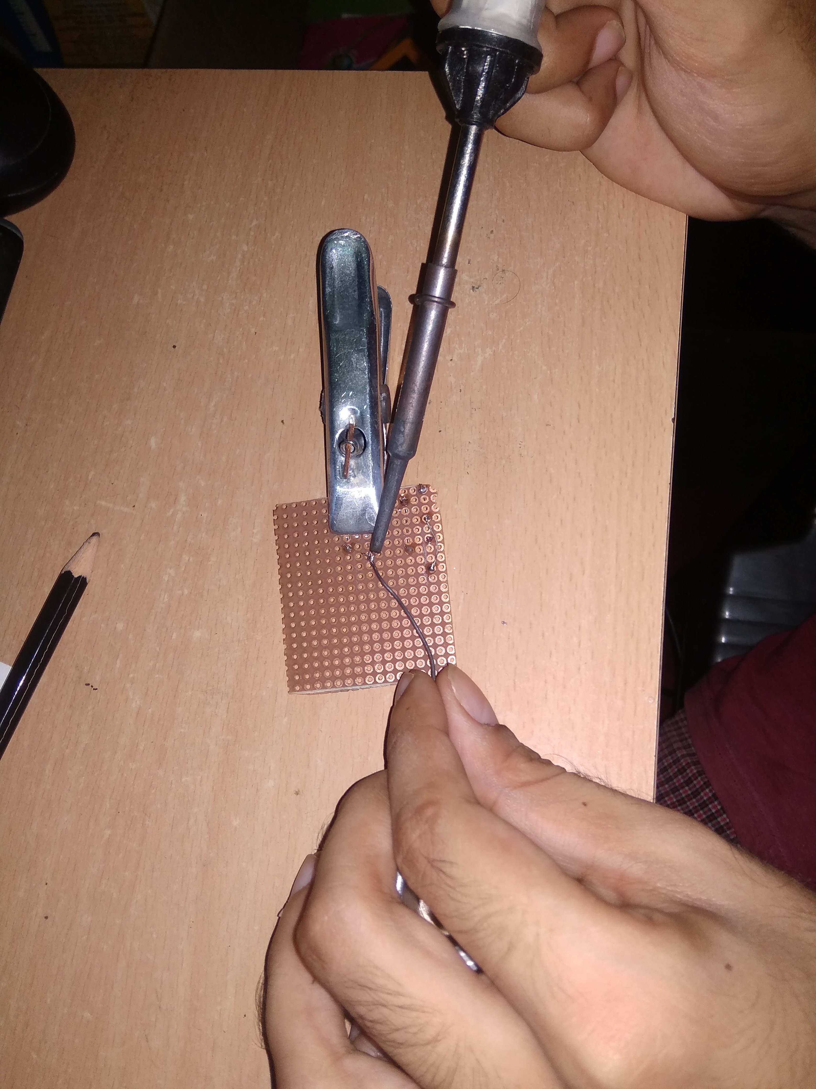
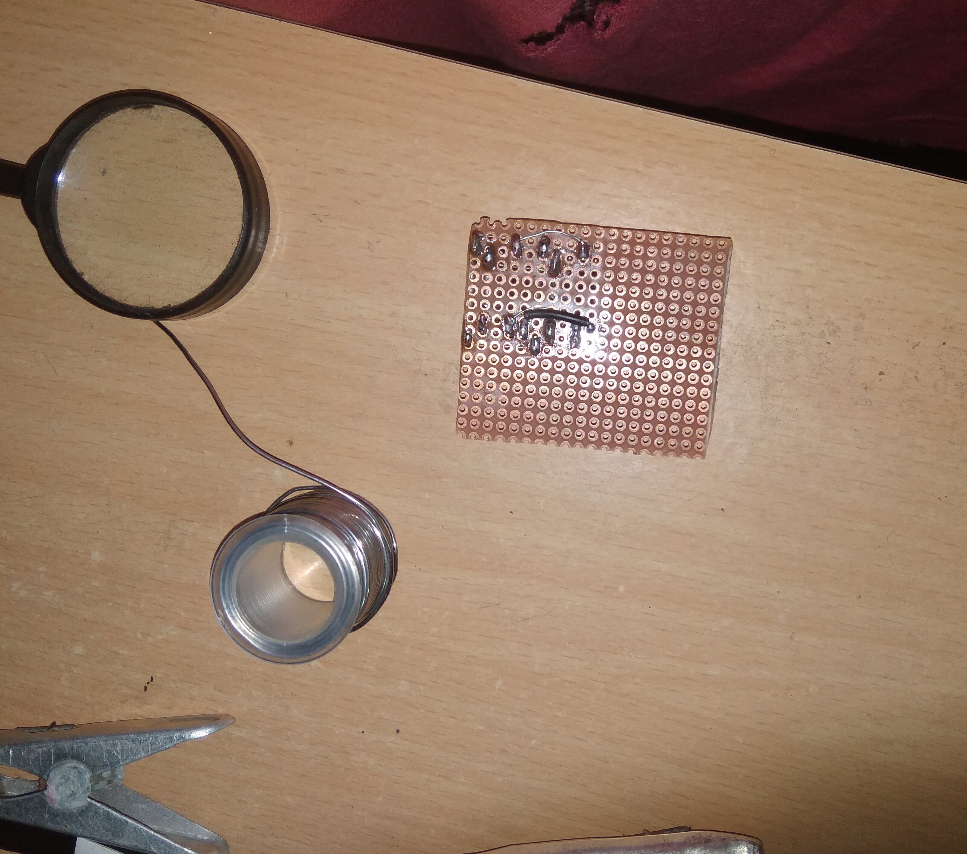
Some perfboarding at midnight
09/26/2020 at 18:18 • 0 commentsMy attempt at shrinkifying everything you saw on the breadboard to fit the enclosure I made from regular epoxy.
![]()
![]()
![]()
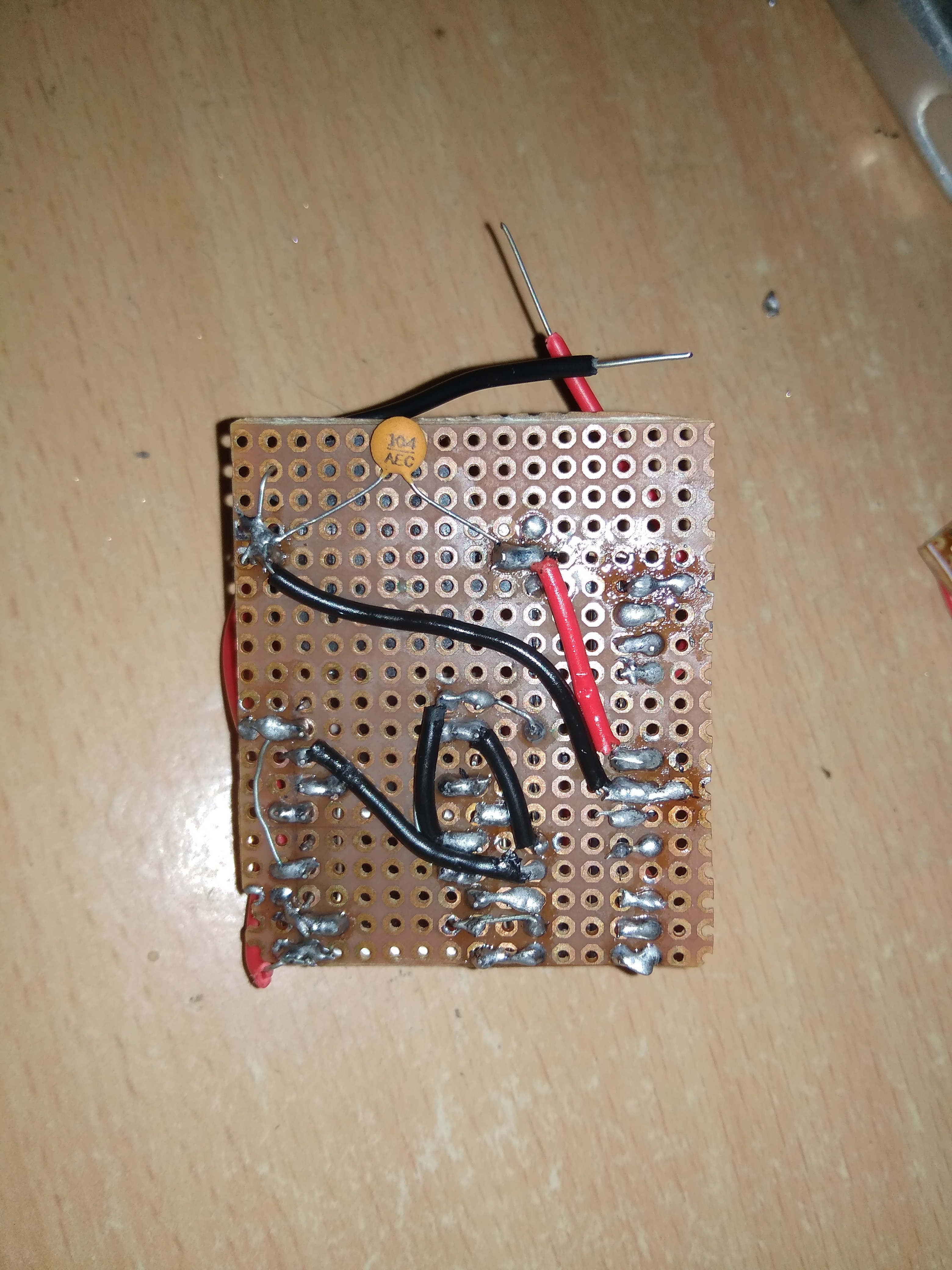
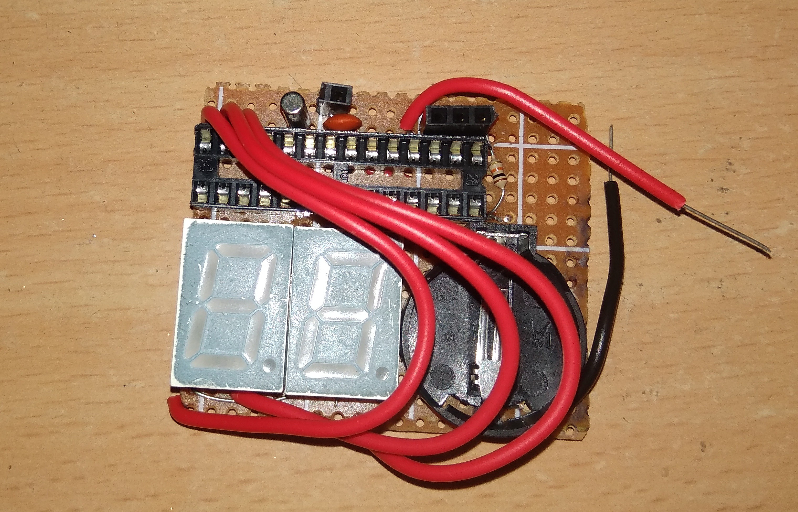
I decided to add an IC socket as that would not consume any extra space and its good practice to add a socket whenever possible. I also added four female headers(to Reset, RX, TX, GND) so that I can program the Atmega without having to remove it from the circuit. And the three red wires could have been connected below the perfboard but I think they would look good on the face of the watch. They add a certain character to it. Don't they?
![]()
-
Building the enclosure
09/26/2020 at 08:44 • 0 commentsI could not 3D print the housing/enclosure because of a lack of finances and the sheer impracticality of ordering anything during a pandemic. I devised an alternative. I made the housing out of regular epoxy. The kind used in sealing pipes and such. Regular epoxy is quite harmless once it is cured. I used it on aquatic snails that had sustained shell damage/deterioration and with no observable ill effects. However, I would warn anyone trying this to monitor themselves for any signs of allergies from the epoxy rubbing against their skin.
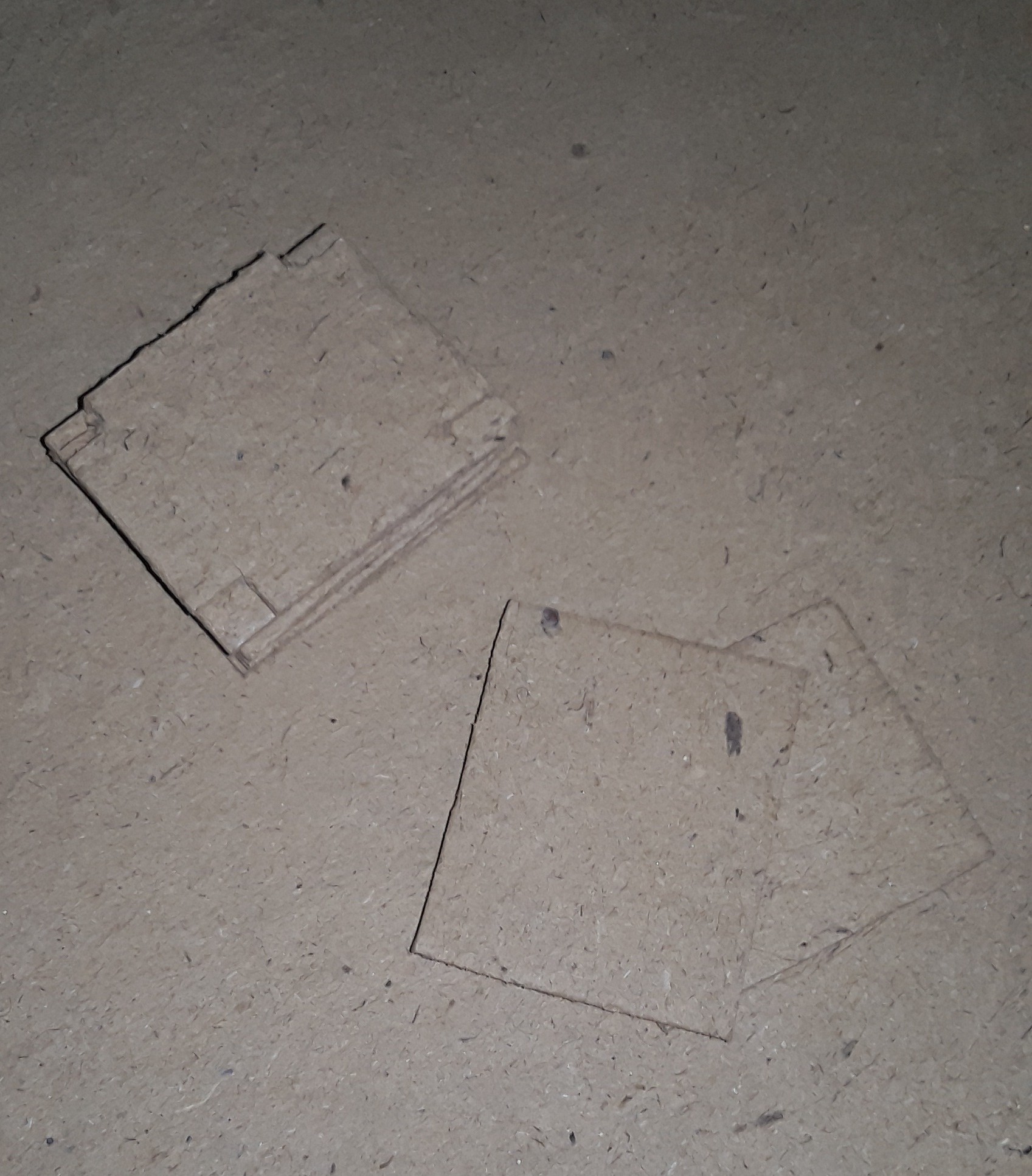
I made cut outs from cardboard and stacked them together into a shape resembling the cavity of the enclosure and then draped epoxy around it.
![]()
The cut-outs
![]()
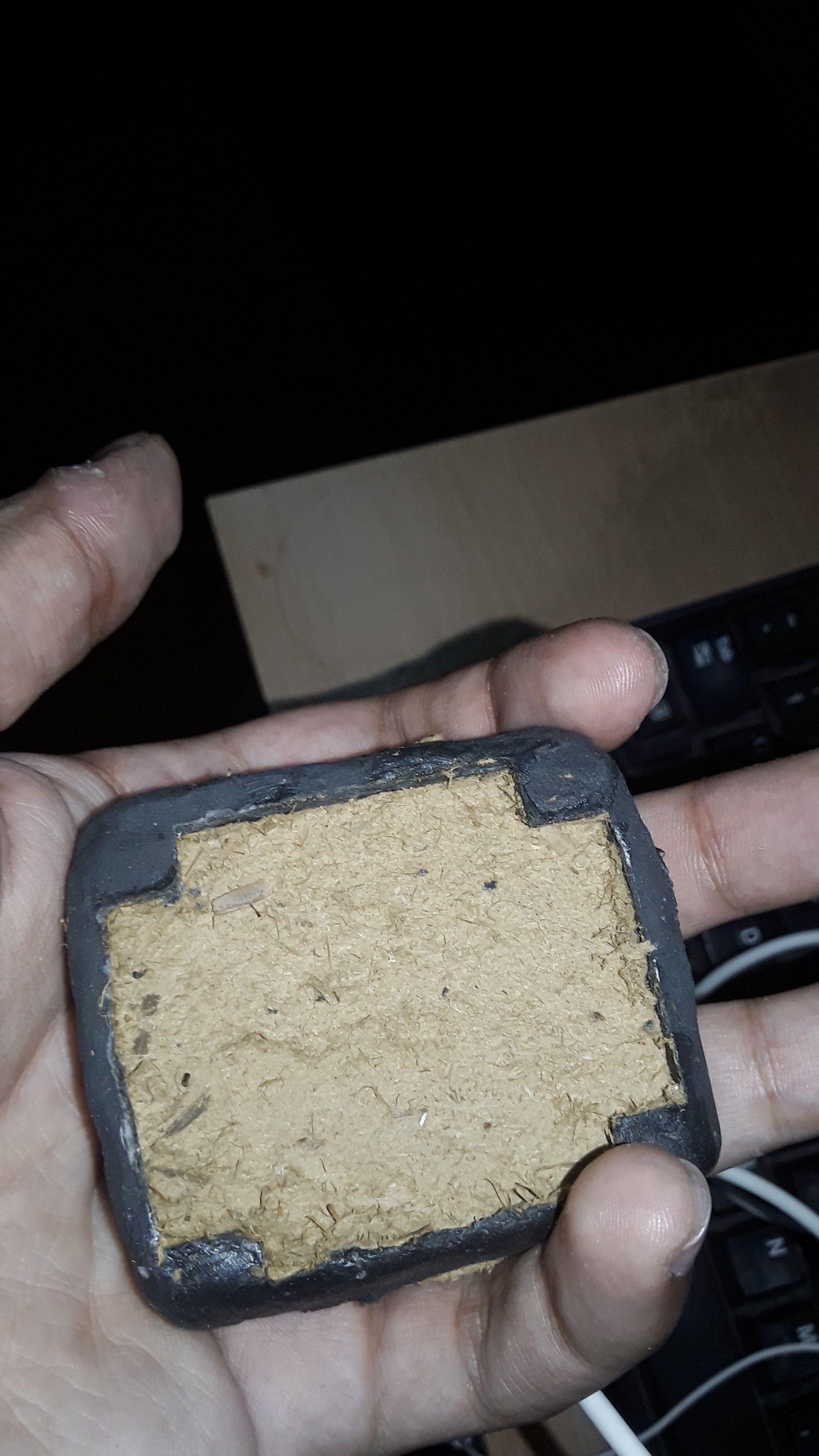
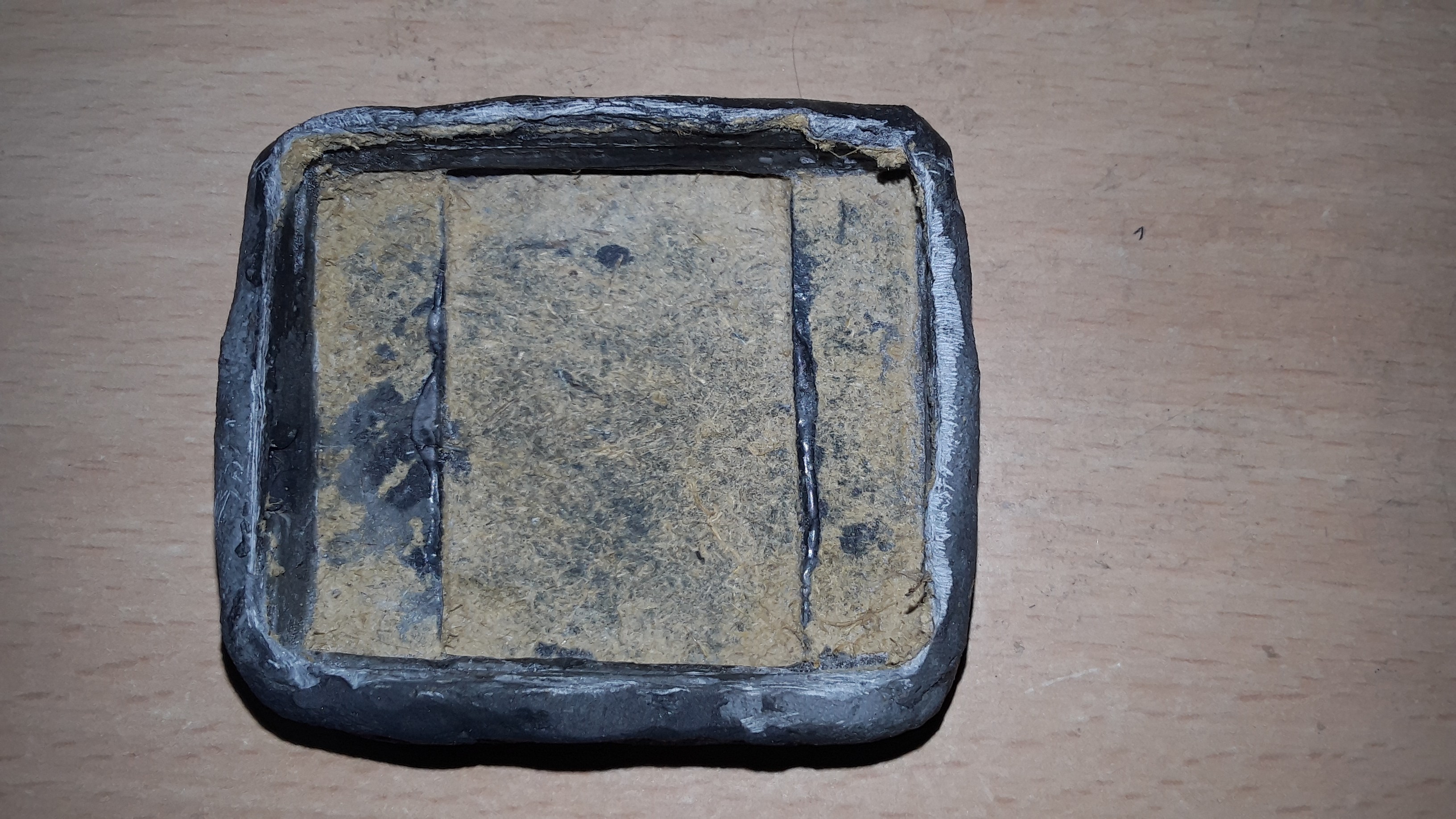
After the epoxy cured, I removed the cardboard by soaking it in water.
![]()
![]()
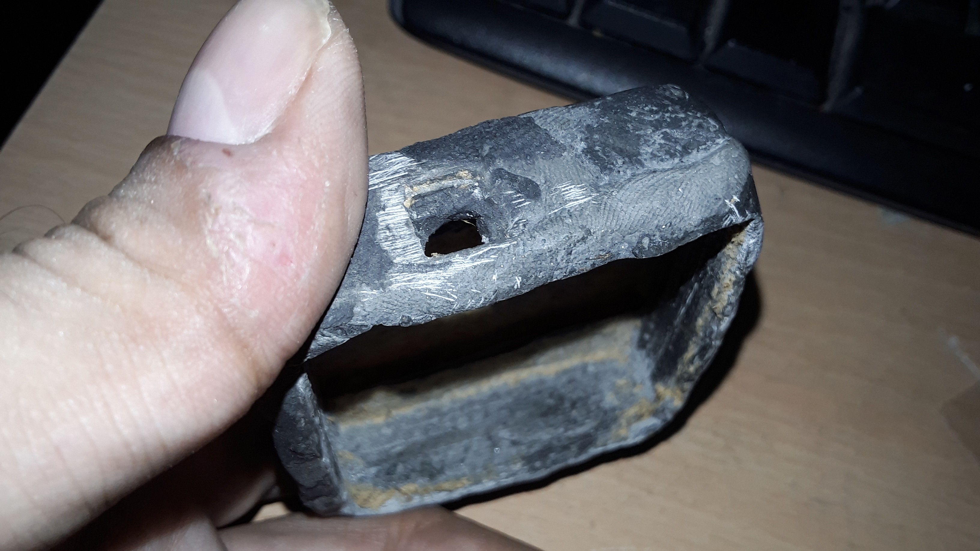
It need a bit of filing and sanding. Some imperfections were repaired by adding more epoxy
-
Builiding it on breadboard
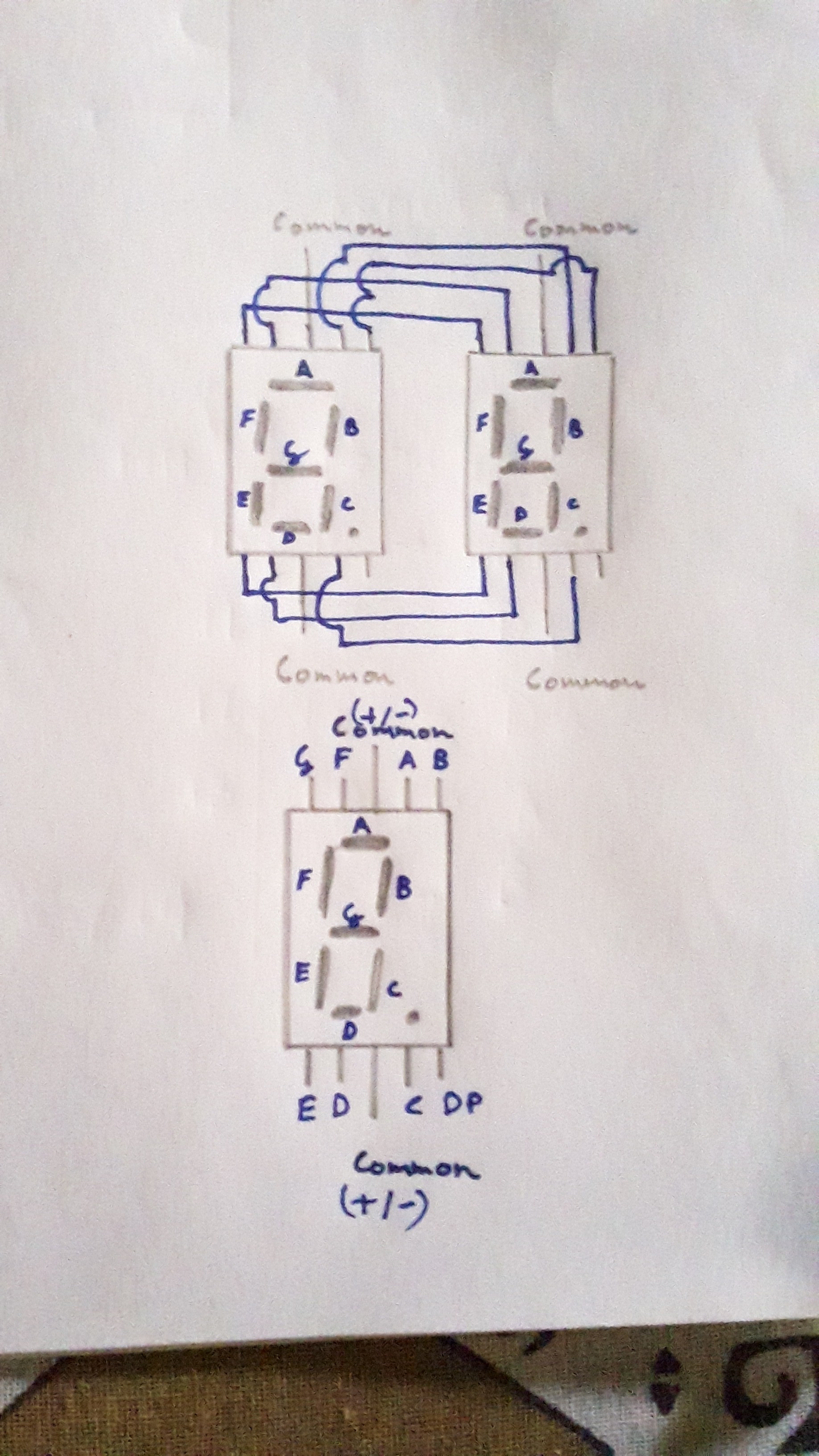
09/26/2020 at 08:13 • 0 commentsBuilding the prototype on breadboard. I connected two common anode seven segment displays to act as one multiplexing unit capable of displaying the two digits for hours and minutes alternately.
Two seven segments can be connected into a multiplexing configuration by connecting their corresponding segment pins together. This is exactly how the commercial multi-digit displays are made. The common pins for each display are left unconnected as these will be used for switching on or off each digit.
![]()
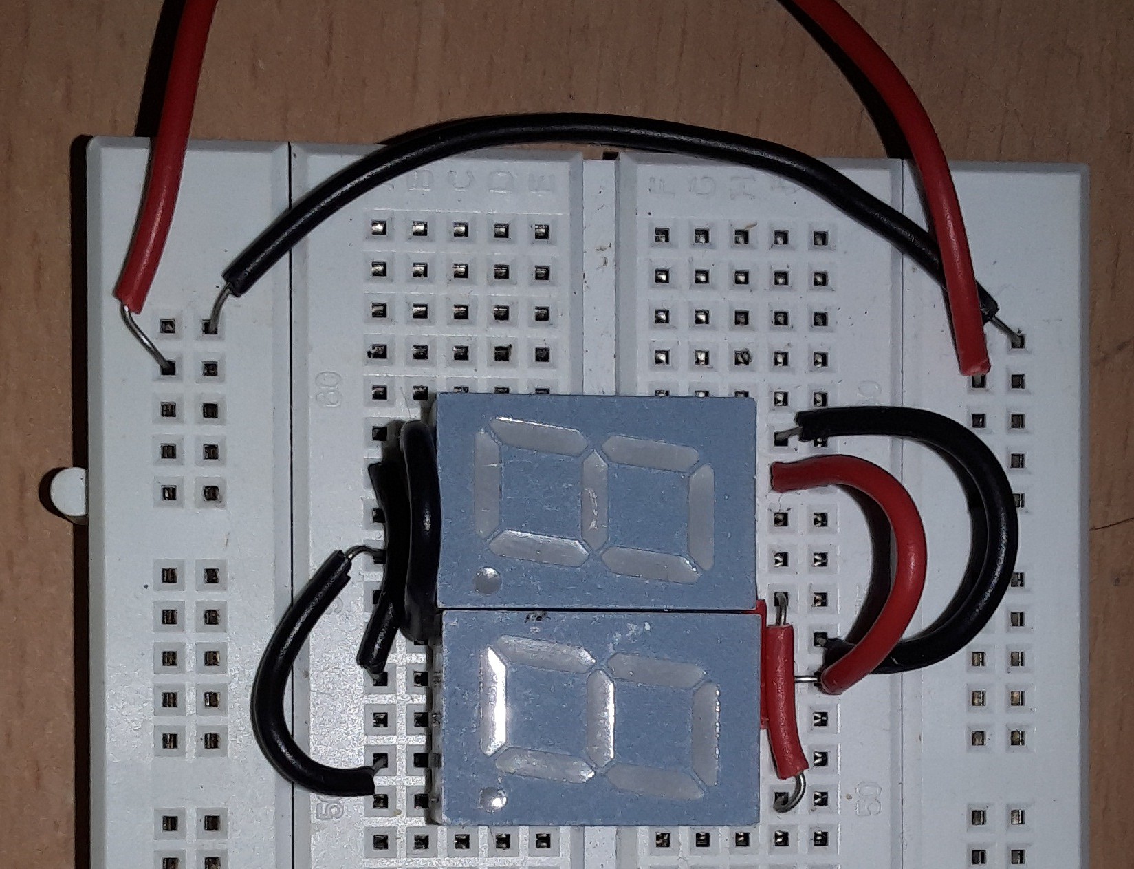
On breadboard the connections look like this
![]()
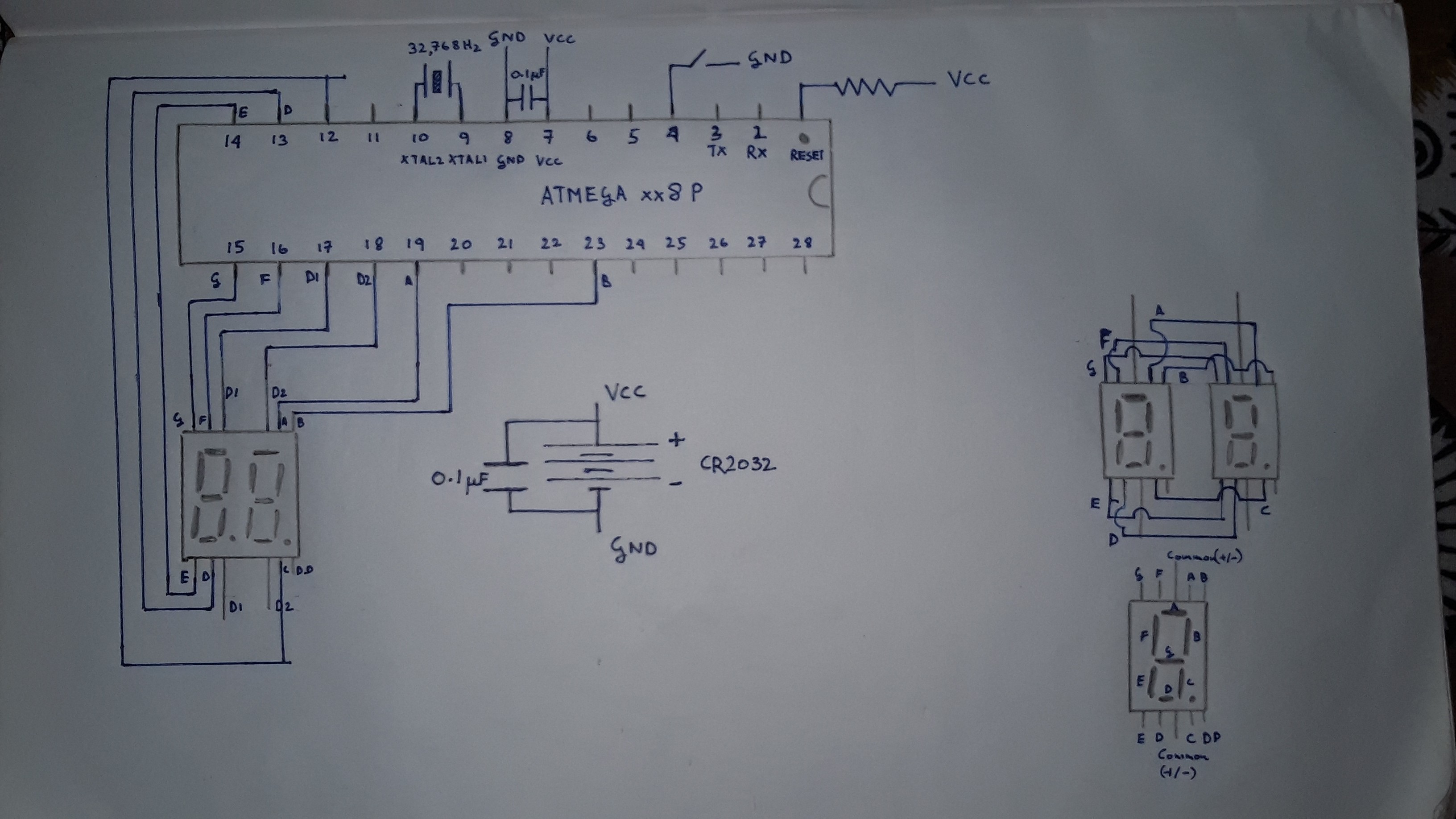
This is the schematic for the rest of the circuit.
![]()
Yeah, I like to be generous with decoupling capacitors on my circuit.
You may have noticed that the watch uses only one button to change the time. This makes the connections a lot easier but it also means that the hours and minutes can only progress in one direction. Not so user-friendly.
After some troubleshooting (mostly faulty jumper wire connections), I got it working!
The video of breadboard circuit in operation can be found in the files.
-
The beauty of clock crystals
09/23/2020 at 12:16 • 0 comments
Any clock needs to extract from the imperfect, random world around it, a precise and periodic signal. There are many ways to do it. One of the most convenient ways of having a periodic phenomenon is to use an oscillating system. Unsurprisingly, most timekeeping devices, from grandfather clocks to atomic clocks use periodic oscillations as a time base. From pendulums to springs to fancy grains of sand to atoms we humans have tried everything. One of our most successful attempts has been at harnessing, what I call, the physics of piezo-electricity. One of the applications of this magical phenomenon is in making crystal oscillators. Piezoelectric crystals, when hit, will oscillate at their natural resonant frequency, like every other object, but they also produce a voltage (or current) every time they are deformed. They can also be made to deform by applying a voltage. With some additional circuitry it is possible to take some of the electricity produced by the crystal and feed it back into the crystal( we make up for the loss by amplifying the current using a transistor). There we have it! An oscillating system that goes on forever. Steve Mould has got a really good video explaining crystal oscillators.When using an AVR chip we have the option of using the internal Resistor-Capacitor(and op-amp) oscillator as the time base but this is not reliable over extended periods. We will be using the 32,768 Hz (or 32kHz) crystal oscillator as the time base. The choice is motivated by many reasons. For one, it is ubiquitous, from digital watches, battery-powered wall clocks to laptops, these are everywhere. Another advantage is that they are low power and do not require loading capacitors for stability. Unlike the battery-powered clocks which use a series of flip-flops to bring down the 32,768 Hz to 1Hz, we are going to use the AVRs timers to generate an interrupt every once in a while and update the seconds counter accordingly. As the timer counts using the external clock signal coming from the crystal we have got ourselves an accurate time base. Just how accurate?
Assuming my crystal has an accuracy of 100 ppm which translates as 100/1,000,000 (hundred over a million) which is equal to 0.0001.
As there are 86,400 seconds in a day, our error will be +/-(0.0001 x 86,400)= +/- 8.64 sec at room temperature.
We can use the AVRs Timer2 which can use an external clock signal. We will use the Timer1 (which will use the internal R-C oscillator at 8MHz) for the delay utility.
TIMER2 is set up in void setup() to overflow every 8 secs.
  TCCR2A = 0x00;
  TCCR2B = 0x00;
  TCCR2B = (1<<CS22)|(1<<CS21)|(1<<CS20);
  ASSR = (1<<AS2);
This generates an interrupt and we update the counters accordingly:-
SIGNAL(TIMER2_OVF_vect)
{
  seconds += 8;
  minutes += seconds / 60;
  seconds %= 60;
  hours += minutes /60;
  minutes %= 60;
}
Kronoino : An AVR powered Digital Wrist Watch
A digital watch using the ATmega 328P and seven-segment displays