-
1Replacing Controller Board
![]()
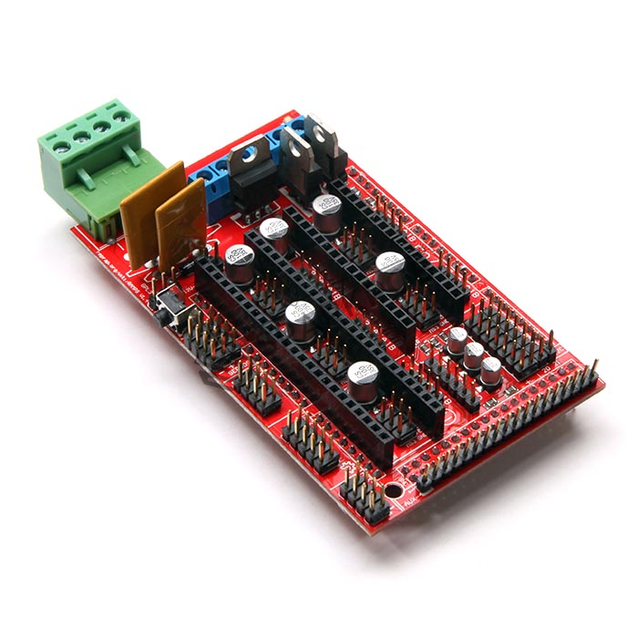
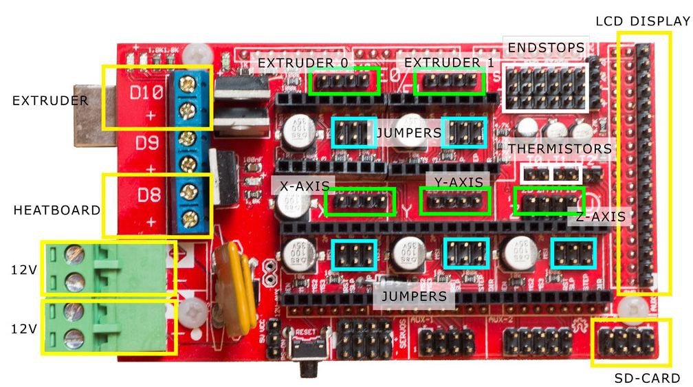
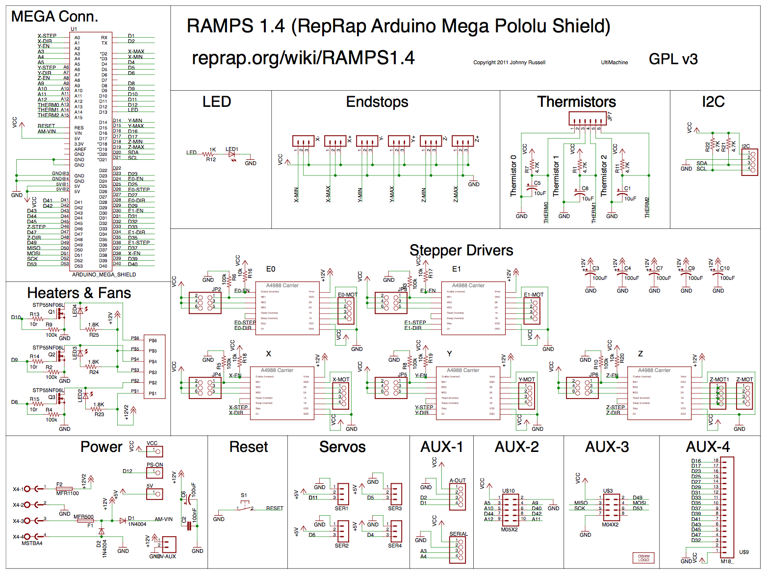
The controller board was replaced with Open Sourced CNC Machine controller board called RAMPS board or in this case RAMPS version 1.4. This board mainly consist of header for microcontroller, limit switches, stepper motor driver , input supply and with polyfuse to protect against overcurrent, mosfet to drive spindle output.
RAMPS 1.4 Overview
![]()
RAMPS 1.4 Schematic
![]()
-
2Replacing Processing Unit
![]()
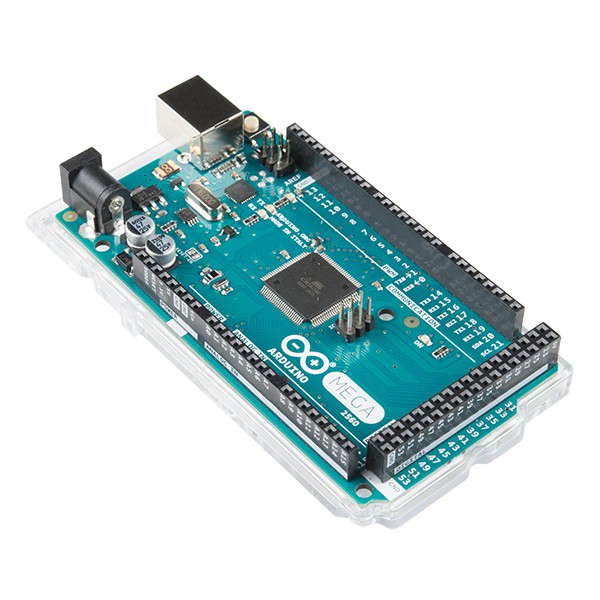
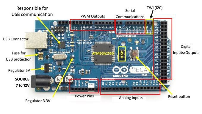
The processing unit was replace with Open Sourced microcontroller board based on ATmega 2560 chip. This microcontroller unit consist of power regulator, UART for USB interfaces, serial communications, and multiple GPIO for controller output.
Arduino MEGA Overview
![]()
-
3Replacing Stepper Motor Driver
![]()
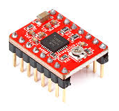
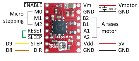
A Breakout board for Allegro’s A4988 was used to control the stepper motors. This board was specifically used to control bipolar stepper motor and features adjustable current limiting, overcurrent and over temperature protection and five different microstep resolutions. It is able to deliver up to 1A per phase without heat sink
Allegro A4988 Overview
![]()
-
4Adding Plotter / Spindle Control
![]()
A spindle control board was designed and fabricate in order to control the solenoid actuator that hold the spindle motor. This spindle is responsible for milling contour and drilling operation and the fact that it is based from solenoid, the operation will differ from normal CNC machine.
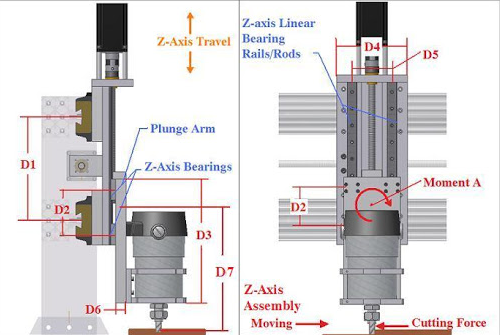
For standard CNC machine, the Z axis (responsible for holding spindle motor) was guided by stepper motor with linear bearing or rods that enables the travel of the spindle to plunge down to a work area
![]()
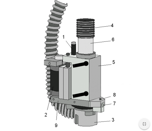
For this machine, originally a solenoid was used instead of stepper motor. In normal condition, the spindle will stay upwards due to the fact that is was hold by spring. Once the solenoid is activated, the spindle will plunge down and when deactivated, the spindle will bounce back to the original position due to the spring action.
![]()
The firmware that was used (explained further in the next section) was based on standard milling operation where in order to drill / mill, the spindle will travel downwards and stays there. This caused problem with this machine where the solenoid does not latch when drilling / milling and it jitters.
A close inspection was made in the operation of the firmware by tapping signal at the pinout of the RAMPS 1.4 board (explained further in the next section) with the help of oscilloscope.
![]()
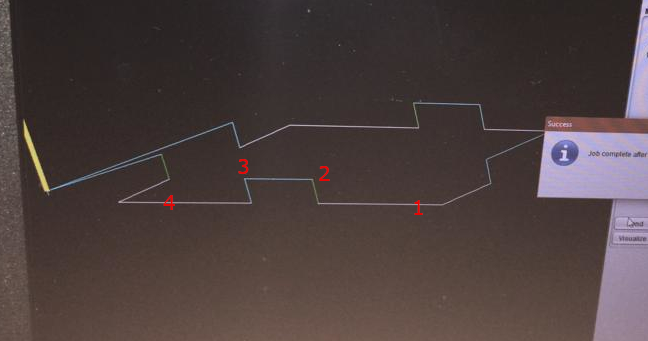
Above shows a mill operation. The operation is as follows:
1 – Spindle is being plunged down and continues so
2 – Spindle moves up
(2-3) Spindle stays at top position
3 – Spindle plunges down to continue milling
4 – Spindle is being plunged down and continues so
![]()
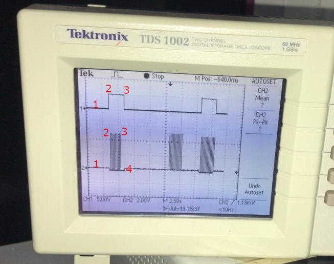
Above shows the signals from RAMPS board. Channel 1 indicates signal for direction and Channel 2 indicates signal for motor stepping.
The jittering of the solenoid was because Channel 2 sends out multiple signals that corresponds with the step angle of the stepper motor that control the travel distance. This is due to the fact that the firmware as made assuming the Z axis was using stepper motor with linear rails/ bearing to drive it.
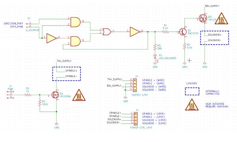
A latching mechanism had designed to overcome this problem.
-
5Solenoid Latching Mechanism
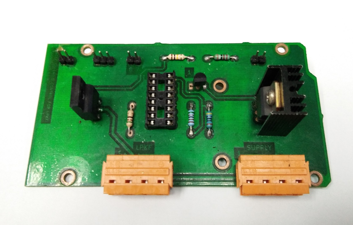
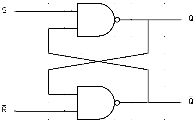
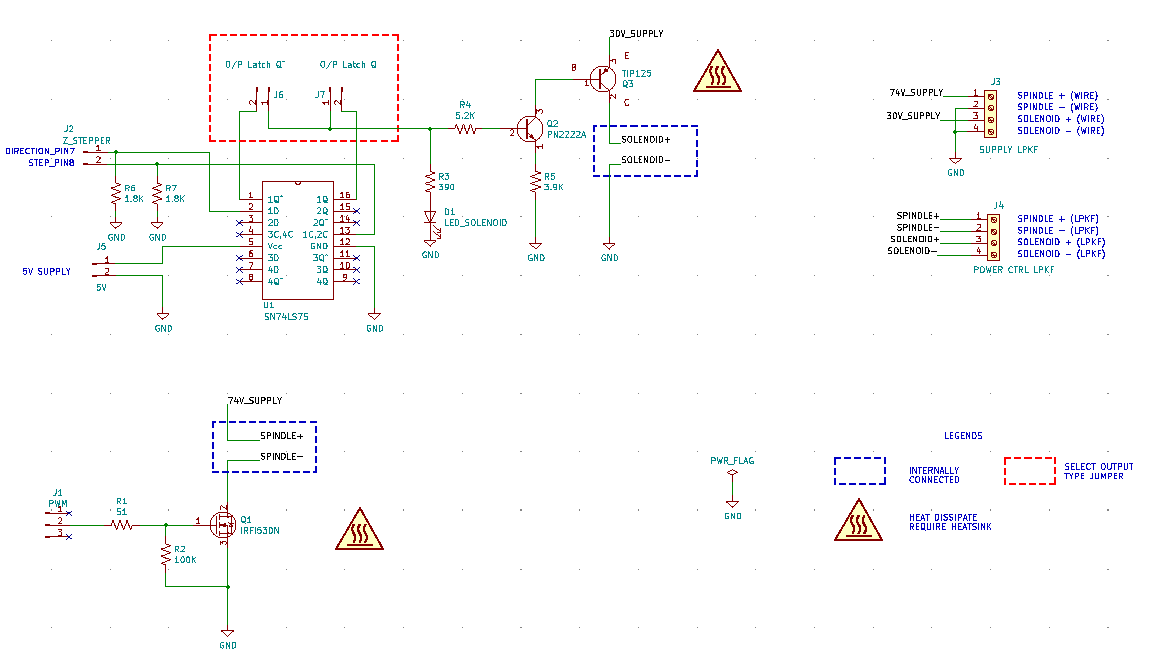
A logic gate was designed based from bi stable latches operation ( SN74LS75 IC) to latch the solenoid until there is a change in the direction signal.
![]()
The PCB schematic is as following. The PN2222 Transistor and TIP125 Darlington Transistor was configured in pair in order to amplify the latching signal from the logic gate current to the solenoid.
This eliminated the jitters of the solenoid during the milling process.
![]()
-
6Flashing GRBL Firmware
![]()
![]()
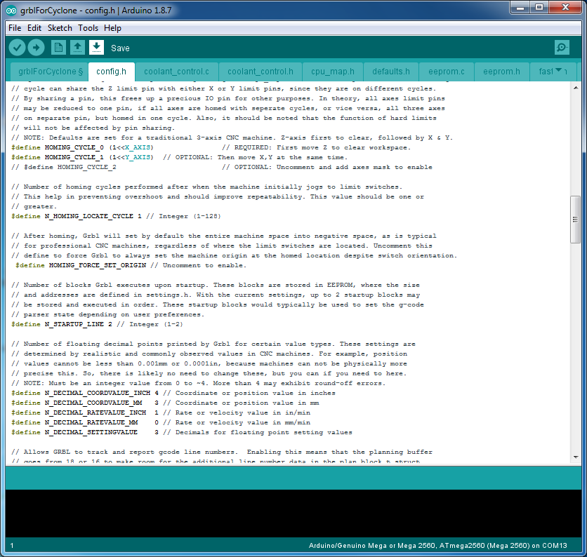
A firmware was needed in order to control the movement for stepper motor and spindle based from design. An Open Sourced GRBL motion control firmware was flashed onto the Arduino Mega microcontroller. The GRBL accepts G-Code commands and was mostly used for Open Sourced CNC based project such as CNC Mill Machine and CNC Laser Cutting Machine. The fact that the codes was written in C with Arduino library, configuring the library to suit this project was a breeze.
( Github library - https://github.com/grbl/grbl)
-
7G Code Sender Application
![]()
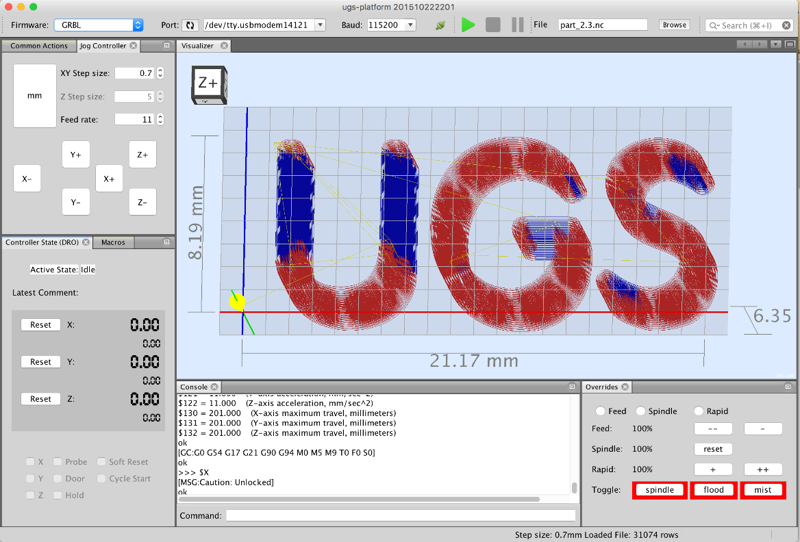
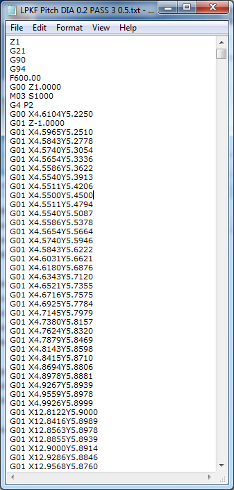
With the use of GRBL firmware, a G-Code commands can be sent through serial interfaces (e.g move X axis for 4cm or start spindle at 4000 RPM) . But with milling operations, it usually consist of thousands of line of commands. Here, the Universal G-Code sender application helps in managing the commands. This applications also provides a visualizer for the commands sent.
(https://winder.github.io/ugs_website/#universal-gcode-sender)
![]()
-
8PCB Milling CAM Application
![]()
![]()
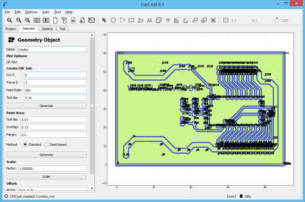
In order to mill a PCB, a CAM software is needed to detect the contour of the design and set the proper parameters in order to achieve the proper clearance. Flatcam reads Gerber file ( PCB layout design file ) and Excellon ( PCB drill design file ) and output a G-Code commands for mill operations
-
9Final Result
![]()
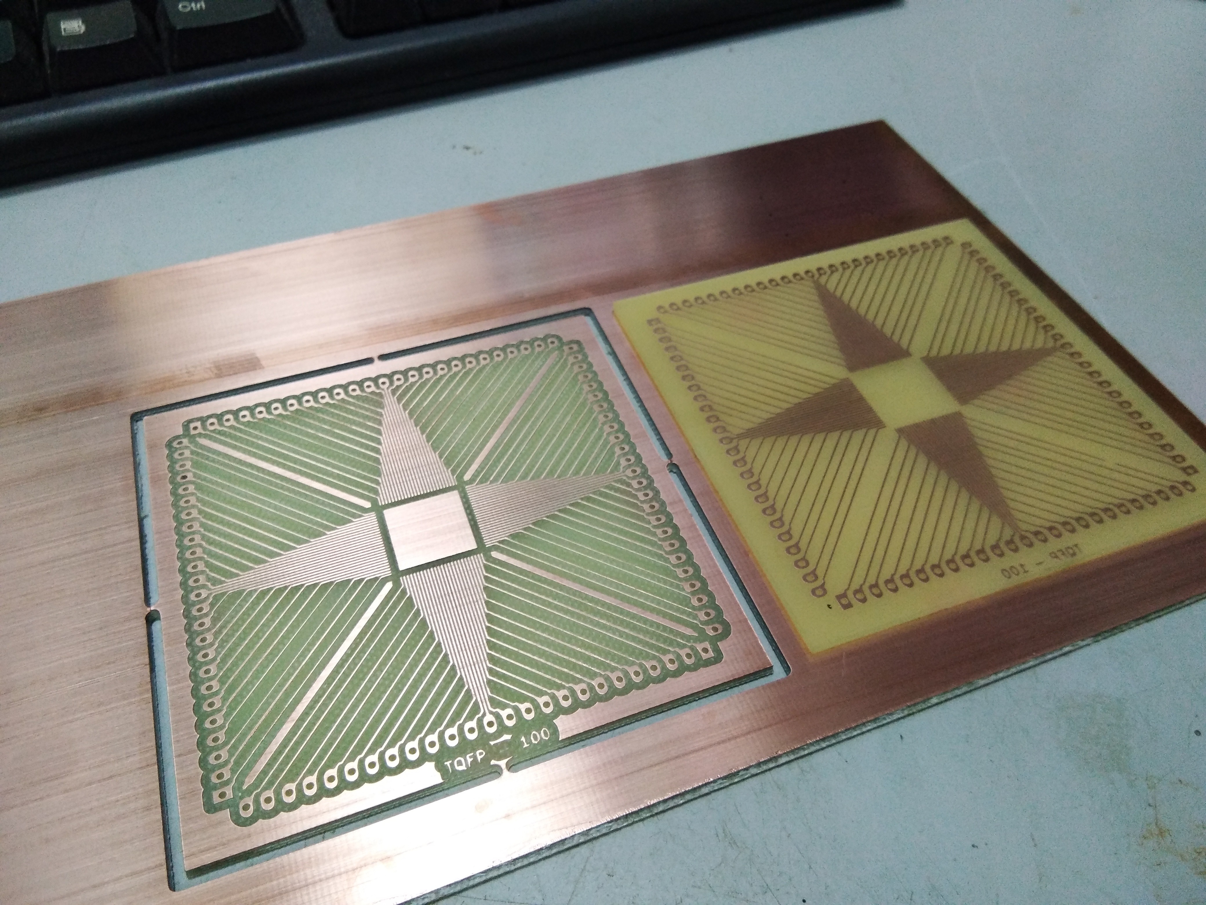
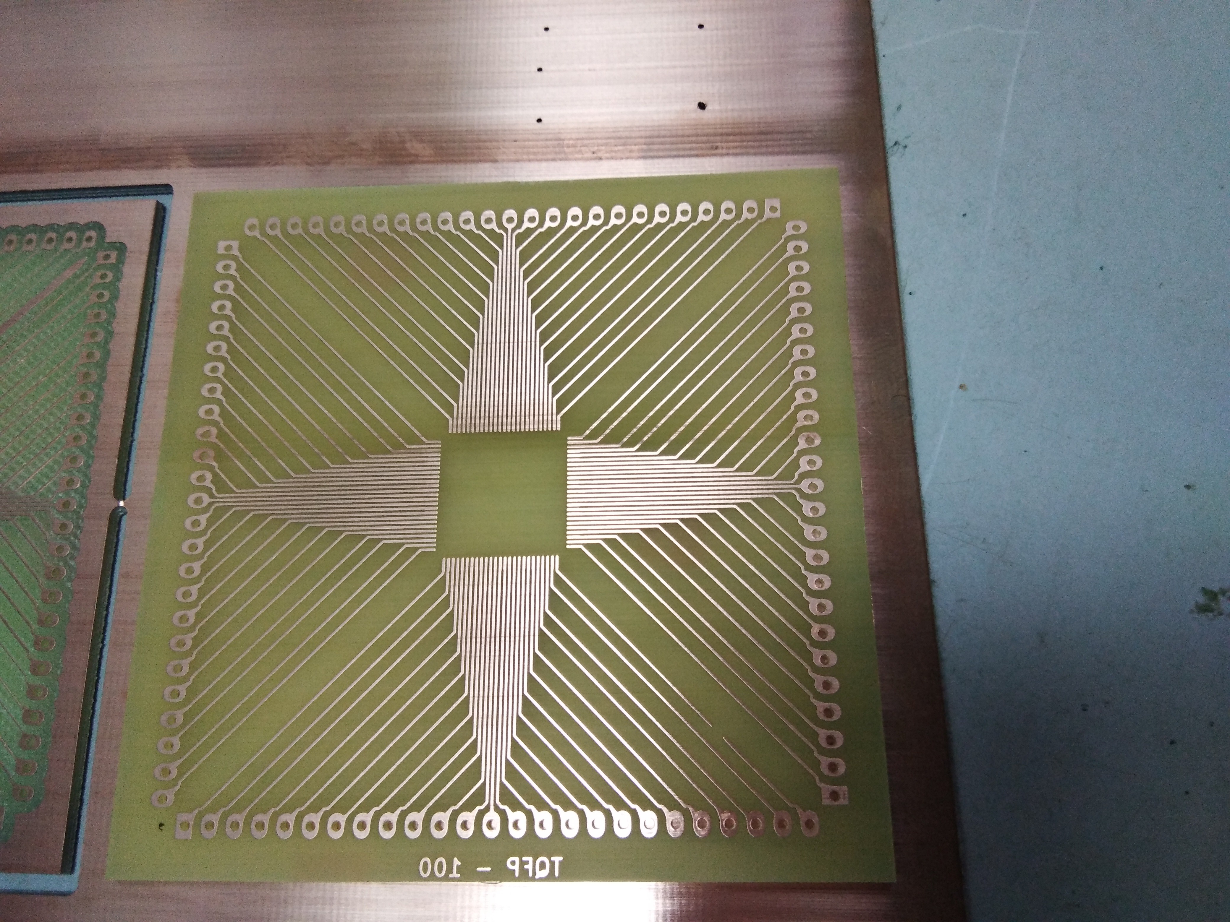
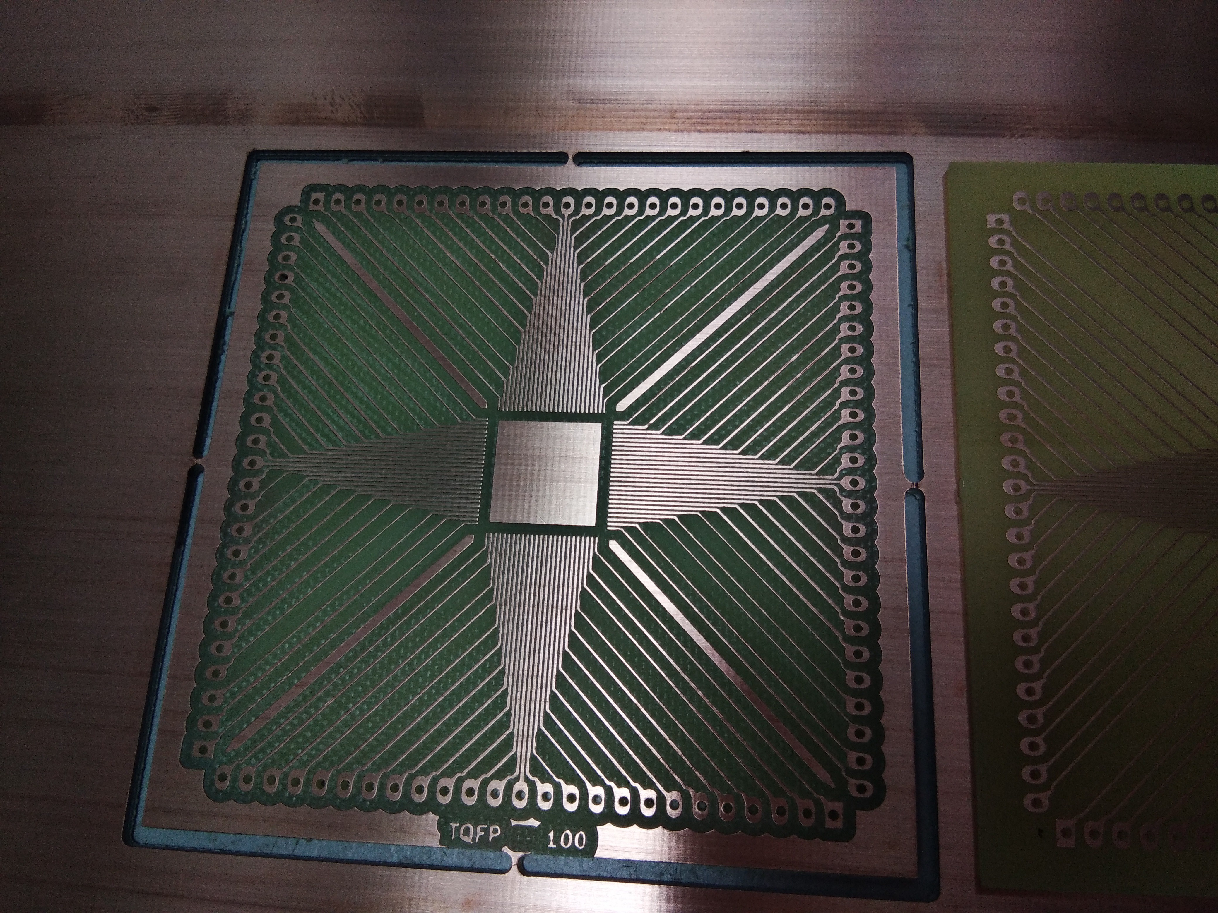
The machine are now able to mill PCB with precision. Below shows a successful 100 pin TQFP footprint with a pitch of 0.3mm milled with the machine and compared side by side with PCB made by etching process.
![]()
![]()
-
10Machine Working
 himynameisNaim


Discussions
Become a Hackaday.io Member
Create an account to leave a comment. Already have an account? Log In.