-
13D Printer modification
Since all 3D printers are different, we will show an overview of each step rather than provide detailed documentation. It basically involves removing two parts from the 3D printer: the extruder and the hot end.
Step 1: Remove the 3D printer parts
We recommend that you remove the filament from the 3D printer in advance. Put the 3D printer on a table and unplug all cables. In case you used the 3D printer in the last hour, you must wait until the hot end is cold again. Do you have all the tools at hand? Then you are ready to go!
- Filament and spool holder
If the 3D printer still has filament, you must first separate the filament from the extruder (break the filament by hand). You can remove the spool holder from the 3D printer with the pliers and screwdriver.
- Extruder
Unplug the extruder cable, unscrew the extruder and remove it. Depending on the length of the extruder tube, you can either put the extruder on the table or just leave it hanging. You will remove this later.
- Fan and hot end
To make the next steps easier, remove the cable tie that secures the protective spiral to the enclosure.
Push with your hand the printhead into a corner. This will make it easier for you to separate the fan from the hot end with the screwdriver. The hot end contains the thermistor (temperature sensor) and the heater cartridge. Both have to be removed from the hot end. To remove the heater cartridge, you need the Hex key. You may have to push the printhead again with your hand.
The protective spiral must also be removed from the printhead . It is attached to the printhead with a screw.
Now you can unscrew the hot end from the printhead. A pair of pliers would be handy here. Put the hot end on the table, you will need it later.
Now you need to unscrew and remove the extruder tube. You may need the pliers for this step. If there is still filament in the tube, apply some force to pull the filament out of the printhead.
The extruder and hot end are no longer attached to the 3D printer. The cables of the fan, extruder, and heater cartridge are still connected to the printer controller board.
● Printer controller board
To access the printer controller board, you must turn the print bed upward by hand and remove the bottom cover of the 3D printer (attached with screws). Now you can work on the printer controller board.
Remove the heater cartridge cables from the printer controller board with the screwdriver, unplug the extruder motor cable and the thermistor cable from the printer controller board. Important: make sure you remember the thermistor connector; the thermistor will be plugged in again later.
The fan cable must also be removed from the power supply. Plug the thermistor back in and leave it on the bottom of the 3D printer.
For safety reasons, 3D printers do not function without a thermistor . You can just leave it on the bottom of the 3D printer. Put the bottom cover back on and now you are done with this step.
Step 2: Modify the hot end
In order for the 3D printer to play a musical instrument, you need to modify the hot end. We have designed two variants: one variant for stringed instruments (zither and ukulele) and another for percussion instruments (güiro).
Depending on the variant (stringed instrument or percussion instrument) you have to separate the nozzle from the hot end (stringed instrument) or you can leave it where it is (percussion instrument).
If you need to remove the nozzle, proceed as follows: the nozzle is probably stuck in place due to the melted filament , in this case you need to apply a lot of force using one or even two pairs of pliers. Applying a little heat to the nozzle will also help. Fortunately, we did not need to do this…
Variant 1: Guitar pick
Here you need a guitar pick and a screw that is slightly longer than the length of the heater cartridge, so that you can attach a suitable nut to the other end. If the opening in the hot end is bigger than the nut, you can simply put a washer between the hot end and the nut.
You need to find the right guitar pick for your instrument. Guitar picks come in different thickness (very soft to very hard). You need to find out the right thickness by yourself. We have opted for a soft thickness.
To attach the guitar pick, drill a small hole in the upper middle area of the pick. You can then simply attach it to the hot end with the screw. The guitar pick must be attached firmly, otherwise, you may have problems later at the programming stage.
Variant 2: Stick
The tube joint from the extruder tube will be helpful. With it, you can easily insert a cotton swab. To separate the tube joint from the extruder tube you will need a side cutter. The cotton swab must be inserted into the tube joint. The cotton swab is now our güiro stick. You can also use different materials for the güiro stick, such as a long screw or a round stick.
If you want more, you can also use the opening in the hot end that you used for mounting the guitar pick to attach a second wooden or metal stick with which you could play a second percussion instrument.
What instruments come to your mind? We do not have any programming for this expansion yet.
Step 3: Fasten the modified hot end and instrument
The modified hot end with guitar pick or stick is screwed to the cylinder (with screw thread) under the printhead so that it is attached to the 3D printer.
After that, you can attach your instrument to the print bed. Since the print bed is mobile, the instrument must be well secured, otherwise you may have problems later at the programming stage.
- To attach the zither, we decided to use a clamp or clip. It is very stable and it attaches to the print bed at the middle of the zither.
- To attach the ukulele, we decided to use Powerstrips, because they are easy to remove. This way you can easily “stick” the ukulele to the printing table. You can also use a large clamp.
- You can also attach the güiro to the 3D printer with a twine. It is also possible to attach it with screws. However, we did not want to drill a hole in the güiro and therefore decided to use twine.
-
2Construction of the zither
The important question now is how to best attach the strings to the wooden board. You can use simple bridges/nuts over which the strings can be stretched. However, we decided to go with hardtail bridges like you find on electric guitars. Since we have 10 strings, we need a total of 4 electric guitar bridges (hardtail bridges). This makes it easier to change the intonation of the individual strings as well as their height. In addition, two single-coils were used as pickups, because they take less space than humbuckers, for example. Single-coils with a chrome-plated cap make the whole conversion easier. The area accessible by the printhead (130 mm Y-axis) offers space for a maximum of 10 strings. To cover as many melodies as possible with it, we decided to use a diatonic scale in E-flat major (Eb5, F5, G5, Ab5, Bb5, C6, D6, Eb6), which offers a minor second (D5) as well as a pure fourth (Bb4) downwards. This allows for playing, for example, upbeat melodies that begin with a fourth (e.g., the well-known “Tedeum” by Marc-Antoine Charpentier). For our 10 strings we use guitar strings. Since a guitar string set usually consists of six strings, we used the five higher ones (A, D, G, B, E) twice and tuned them as described above. Since some are more tensioned than others, (e.g., to get from an A to a D) it was necessary to use strings of different gauges (see table). The reason for raising the notes of our zither by an octave is that the string lengths of our zither are only half as long as those of an ordinary guitar. This provides a higher pitch range, which seems to be more suitable for melodies in particular.
String
Pitch
Guitar string
Gauge
Interval
10
Eb6
E
9
8
9
D6
E
11
7
8
C6
B
11
6
7
Bb5
B
14
5
6
Ab5
G
16
4
5
G5
G
18
3
4
F5
D
24
2
3
Eb5
D
28
1
2
D5
A
32
7
1
Bb4
A
38
5
Construction of the zither step by step
Once you have all the necessary components and tools that can be found in the components sectionof the project, you need to determine the available space on your 3D printer. The zither will be designed on paper according to the size and print area (X or Y) of the 3D printer.
How many strings will fit on the print area? The first string should not be on the edge of the print area. The guitar pick should be separated from the first and the last string by at least 1cm, otherwise it will not be able to pluck the strings.
How big should the wooden board be? Since your zither will be moved inside the 3D printer, the zither and the 3D printer should be at least 3 mm apart.
You can use different patterns for your design: the zither can also look like a guitar. But this will require more time to make the wooden board. Our pattern is quite simple and basic. It does not look very fancy... yours could be prettier.
You should make sure that the pickups are placed on the print bed of the 3D printer, so that the weight of the zither is better distributed on the 3D printer. Also, the wooden board must be positioned in the middle of the 3D printer.
Once you have all your ideas on paper, you can cut the wooden board with the jigsaw. Then you can place all the parts on the wooden board in the right position and mark these positions (the pickups in the middle, the electric guitar bridges and the tuners towards the strings, and the jack near the pickups).
Drilling the wooden board
The best place to start is with the microphone holes. To make these holes, you first need to drill two holes at the corners using the Forstner drill bit. The 15 mm Forstner drill fits perfectly for the single-coil pickups. Once the two holes are done, you can use the jigsaw to finish the job. Since the pickups are larger in the lower part, you will need to use the chisel and files to widen the hole so that the microphone can be inserted into the wooden board. The upper part of the pickup may be up to 3 mm above the wooden board. Once the pickups fit into both holes, you can move on to the next step. You will install and attach the pickups later.
The holes for the tuners are an easier task compared to the microphone holes. You can drill the holes with an 8 mm wood drill bit. Since the tuning posts of the tuners have two different sizes, the hole on the back part of the wooden board has to be a bit wider. We drilled through about 5 mm with the 10 mm wood drill bit. Now you can check if the tuner fits into the hole. You can enlarge the hole with the file. Depending on how many strings your zither has, you will have to drill a corresponding number of tuners holes. You will install and fasten the tuners later.
The last hole is for the guitar jack socket. With it, you can connect the zither to your amplifier. Here we will drill a hole in the shape of an “L”. We will start from one side of the wooden board and the hole will end on the back part of the wooden board. Using a 12 mm Forstner drill (or the size of your jack socket), you need to drill a hole 7cm deep (or the length of your jack socket) in the side of the zither. This hole should be near the pickups. Since your wooden board is very thin (about 18 mm), you need to be very precise. The Forstner drill could easily break the wooden board if it has even a minimal tilt. Did everything work well? Now you have to drill through the wooden board from behind about 10 mm until you hit the first hole. Now the “L” hole is ready.
Using the chisel, you need to remove about 2 mm from the wooden board between the pickup and the jack socket. This is where the pickup cable will be placed later.
You are now done with the holes. To make your zither look fancier, you can paint and varnish it now. This is not covered in this tutorial.
Assemble the parts
Since the microphone holes are difficult, it's best to attach the pickups first. The pickups must be inserted from behind. The upper part of the pickups can be up to 3 mm above the wooden board. You can now fasten the screws that come with the pickups with a PH-0 screwdriver. You will take care of the electronics in a moment.
When the pickups are fixed in place, you have to fasten all the electric guitar bridges with the supplied screws and the PH-0 screwdriver. Are the bridges in the correct position in relation to the pickup? If not, you need to place the bridges on their correct positions and then fasten them. You can also use a 3 mm wood drill to drill the hole for the bridge screws.
Then insert the tuners into the holes and fix them in place.
Now you will work on the jack socket. Insert the jack socket from the side and fasten it. Once the jack socket is fastened, you have to connect the pickup cables to the jack socket and solder them. Please pay attention to the diagram in the animation.
Now you need to cover the bottom of the wooden board with cardboard and put on the guitar strings, tune them and, of course, test your homemade zither.
-
3PureData Patch explained / Programming
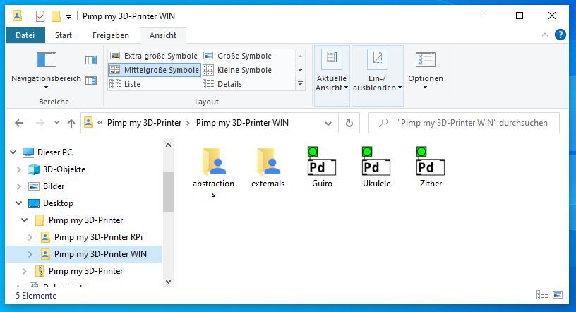
As soon as you open the { Pimp my 3D-Printer WIN} folder, you will see the following directory:
![]()
There you will find our instruments, the zither, ukulele and güiro, each in the form of a Pd patch. We will first explain how to control and edit the program using the most complex of these three: zither.pd. At relevant passages, you will also find hints for using the patches güiro.pd and ukulele.pd.
In addition to the individual Pd patches, you will find two important folders:
- The abstractions folder contains some necessary Pd snippets provided by the Pd community, which we are allowed to use in our patch. If you want to extend your own Pimp my 3d-printer patch with external abstractions , you can add them here.
- Likewise, the externals folder contains additional material that our program uses in the form of libraries. These files are very important, because their functions affect our patch extensively.
Let's get started with the zither.pd !
Overview of the user interface
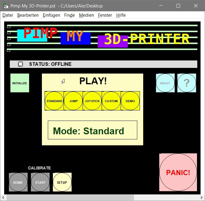
![]()
When opening the patch, you can see several buttons for selecting the playing modes. Above them there is a status bar with a gray background, which shows whether there is a connection to the 3D printer (online) or not (offline).
In order to be able to use the 3D printer as a zither (or güiro or ukulele) at all, you must perform a one-time, small-scale calibration. For this you will find instructions under the ? button, which you have to follow first. The corresponding setup options can be found under the yellow SETUP button. After the setup you can reset the printer to its zero position (HOME ) or bring it to any calibrated playing position (START ).
The PANIC! button ensures that in the event of a mechanical override or error, the current operation can be aborted to prevent damage to the hardware and motor.
Important: If the PANIC! button does not work, you should remove the power cord from the 3D printer and close Pd, then try again.
Bonus:
If you scroll to the right on the interface, you will see all the subpatches that are important for the program. As a beginner, you should not change them and may safely ignore them. Advanced Pd users: feel free to check them out for inspiration!
Communication and data transmission
The most important prerequisite for the communication between the program and the 3D printer is the serial connection, the so-called COM port. After the printer is connected to the computer via a USB cable, you must enter the corresponding port number once. To do this, click on the SETUP button, which opens the Calibration Panel. The yellow main display now shows us that we are in calibration mode.
In this window you will find on the top row a two-part module, COM-Port and PrinterComm. Here you must first enter the serial port (COM port) used by your printer. To be sure, click on Show available ports to see the correct port number in the Pd console.
Since most 3D printers work in a similar way, you can safely ignore the port speed (Serial_Port_Speed ) as well as the PrinterComm module for now and only change or fine-tune it if it is not working properly. After entering the port number save this setting with SET!.
Now you can click on the INITIALIZE button back in the main window to establish the connection with the printer.
📣 If you are unsure at this point, follow the links to G-Code below and refer to your 3D printer's documentation for guidance on your specific model.
After you initialize the printer, the display will show “Waiting for Start Position”. This is where we wait for both the printhead and the print bed to move to the playing position:
- The printhead moves to the zero position of the printer, called HOME in our patch.
- The print bed moves to HOME accordingly.
- The printhead moves to the preset playing position, which is the position where the guitar pick is closest to the first string. In our patch this position is called START . Later, the program will adopt the values you set for START during calibration.
- The print bed moves to START accordingly.
The whole process takes about one minute. As soon as this has been done successfully, the display will show “Online”. The printer is ready!
The G-Code language
Most 3D printers run using the special G-Code standard. To do this, Pd must communicate with the printer in ascii coding language using a Pd-abstraction that correctly converts our commands to move the printhead linearly.
For example: the G-Code message “G1 X30 F5000” commands the printer to go to “position 30” on the X-axis at a speed of 5000 millimeters per second.
Follow the link to learn more about G-Code.
📣 Each machine uses ready-made subroutines (cycles) that are adjusted with parameters or variables. It is recommended to check the documentation of your 3D printer model to avoid errors or problems. You can read a more detailed explanation on setting up 3D printers here.
Calibration of the printer depending on the instrument
📣 Before you start with the digital part of the calibration, make sure that all parts of the printer are movable and that the print bed is at the bottom so that you can mount the instrument.
Warning: It is essential to perform this setup before the first use or when changing the instrument.
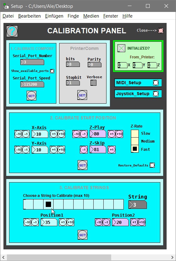
If the printer indicates that it is online, we can open the Calibration Panel by clicking on SETUP in the main window of the corresponding instrument patch.
![]()
In the Calibration Panel, we must look carefully and enter the correct values for all variables depending on the instrument or model of the 3D printer:
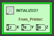
0. Check the data transmission
First of all, we can check on the right side on the green Initialized? area to see if everything is working properly. It shows us the status of the connection with the printer as well as the incoming axis values, i.e. the values that are transmitted from the device through the COM port into the Pd patch.
![]()
1. Calibrate the COM-Port
In the first module on the left, you can enable or configure the COM port, as described above under Communication and Data Transmission. This step is not only necessary for the calibration that follows, but also for the correct functioning of the instrument patches.
2. Calibrate the Start Position
To set the playing position we use the module on the second row. First, you set the desired values by pressing the buttons in 1- or 10-millimeter increments: the printer will respond immediately. If that does not suit your instrument, keep fine-tuning the values.
The purple values for the Z variable indicate the height of the print bed. You can choose from three different speed levels (Z-Rate). Z-Play, for example, tells us the height at which the strings are plucked. And Z-Skip determines the minimum height necessary to skip strings and thus efficiently drive the guitar pick through the playing surface. This means you should pay attention to both values and their correlation. Then click SET! to set your values for the start position and save them.
Now you can check at the main window if everything works correctly by clicking on START. Both the printhead and the print bed should now move to the desired start position and display your own values for X, Y and Z respectively on the green Initialized? module.
When you open the patch afterwards, this motion should always happen automatically at steps 3) and 4) of the printer initialization.
Default guitar pick positions or axis values:
Home:
- X = 0 = Left
- Y = 0 = Bottom
- Z = 100 = Bottom
Maximum range:
- X = 150 = Right
- Y = 130 = Top
- Z = 0 = Top
3. Calibrate the strings
Each string can be plucked by the guitar pick from the “front” or the “back” as desired. In order to play our instrument correctly, we now need to adjust the exact heights of the two playing positions (forward and backward) for each string individually. It is tedious, but it is worth the effort. For this purpose, select a string for manual adjustment in millimeter steps, just like in the previous step. Click SET! at the end to save the last values.
Bonus:
Advanced users can look into the Midi_Setup or Joystick_Setup subpatches to configure other input devices and try out advanced playing modes.
Overview of the playing modes
Once you have calibrated your 3D printer, you need to select the playing mode and now your 3D printer is finally ready to make music!
Zither:
- Standard: plays single strings without skipping other strings. Can play up to 10 strings either with a keyboard (keys 1 to 0, where the “1” key corresponds to the first string and the “0” key to the tenth string) or with the MIDI device. In the chapter “Construction of the zither”, you will find the pitch of the strings.
- Jump: plays single strings while skipping other strings. Works with a keyboard or with the MIDI device.
- Joystick: moves the guitar pick with the help of the joystick without skipping strings. Recommended for advanced players.
- Custom: offers the possibility to code your own subpatch. Recommended for advanced users.
- Demo: plays “Alle meine Entchen” automatically.
Ukulele:- Standard: plays single strings without skipping other strings.
- Rhythm: automatically plays a pre-programmed rhythm. Here you can change the tempo of the rhythm.
- Joystick: moves the guitar pick using the joystick without skipping strings. Recommended for advanced players.
- Custom: offers the possibility to code your own subpatch. Recommended for advanced users. Here you could program your own rhythm.
Güiro:
- Standard: moves the stick using the keyboard or MIDI device.
- Rhythm: automatically plays a pre-programmed rhythm. Here you can change the tempo of the rhythm.
- Joystick: Moves the stick with the help of the joystick. Recommended for advanced players.
- Custom: offers the possibility to code your own subpatch. Recommended for advanced users. Here you could program your own rhythm.
Discussions
Become a Hackaday.io Member
Create an account to leave a comment. Already have an account? Log In.
You can also find all instructions in a PDF file we uploaded.
Are you sure? yes | no