Close
0%
0%

Graupner MZ-32 DSM/DSMX Adapter Module

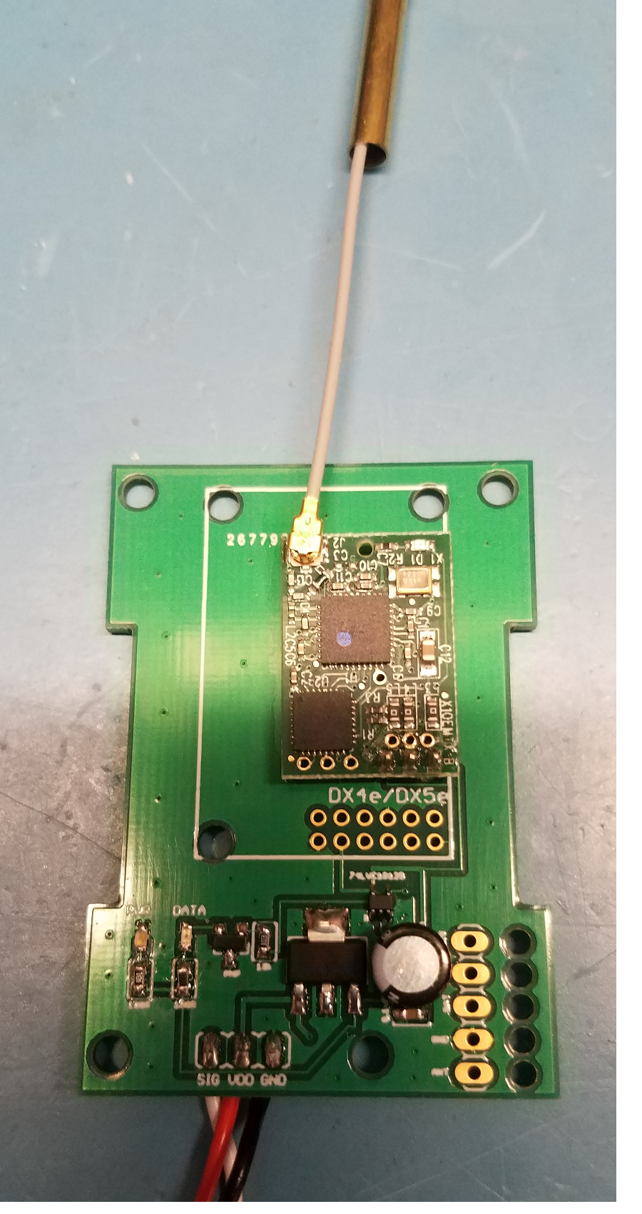
This is a DIY DSM/DSMX RF Module adapter for your Graupner MZ-32 Radio, using a harvested OEM DSM Module from a genuine Spektrum/HH Radio.

Similar projects worth following
This project shows you how to assemble/build your own DSM/DSMX module for your Graupner MZ-32 Transmitter (or other Transmitter with JR compatible module bay).

The design uses a HARVESTED 'OEM' Horizon Hobby DSM/DSMX RF Module from a genuine Spektrum Tx, like a DX5e, DX6e, MLP4DSM, etc.

This is the most straighforward and trustryworthy approach to getting guinine DSM support out of your non-Spektrum/HH radio, since currently HH no longer sells their 'DSM Air' modules as they have in the past.

*** This design is based around the Horizon Hobby DM9 empty air module case (https://www.horizonhobby.com/product/integrated-case-for-jr-compatible-air-module/SPM6817.html)

** Credit goes to John Prikkel for his original DSM module design, as I used his PCB dimensions in order to easily layout **

parts list:
-----------------------

1)  OEM DSM/DSMx RF Module   (harvest from Genuine DSM radio)    ----      qty 1      - approx  $40.00

2)  PCB  (JLCPCB or OshPark)                                                                 ----      qty 1      -  $16.75

3)  74LVC1G125 line driver -      digikey:  296-11604-1-ND                      ----      qty 1      -  $0.26

4)  UA78M33   3.3v regulator - digikey:  296-13424-1-ND                      ----      qty 1      -  $0.58

5)  200 ohm resistor  - digikey:  P200HCT-ND                                      ----      qty 10    - $0.32 (per 10)

6)  100 ohm resistor - digikey:  P100HCT-ND                                         ----      qty 10    - $0.32 (per 10)

7)  10k ohm resistor - digikey: P10KHCT-ND                                           ----      qty 10    - $0.32 (per 10)

8)  20 ohm resistor - digikey: P20HCT-ND                                            ----      qty 10    - $0.32 (per 10)

9)  PNP transistor - digikey: MMBT2907ALT3GOSCT-ND                     ----      qty 1      - $0.15

10) 0.1uF cer cap - digikey: 478-6206-1-ND                                            ----       qty 1      - $0.24

11)  orange led - digikey: 160-1445-1-ND                                                  ----       qty 1      - $0.24

12) blue led - digikey: 160-1646-1-ND                                                     ...

Read more »
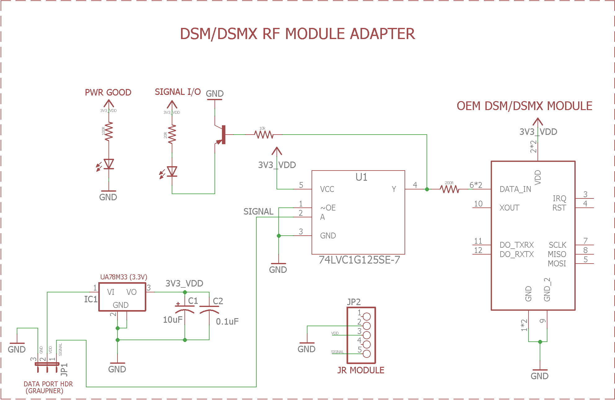
DSMX_Adapter.png

Schematic in PNG format

Portable Network Graphics (PNG) - 33.86 kB - 10/18/2020 at 23:04

Preview

RC_DSMX_Adapter.zip

Eagle (7.7.0) Schematic and PCB files

x-zip-compressed - 78.43 kB - 10/18/2020 at 23:04

Download

  • DSM/DSMX Schematic

    PhillyFlyers10/18/2020 at 23:06 0 comments

    In case you just wanted to view the schematic (Eagle PCB/SCH files are attached to this project in a zip file)

  • MZ-32: Binding with the DSM Module

    PhillyFlyers10/18/2020 at 22:46 0 comments

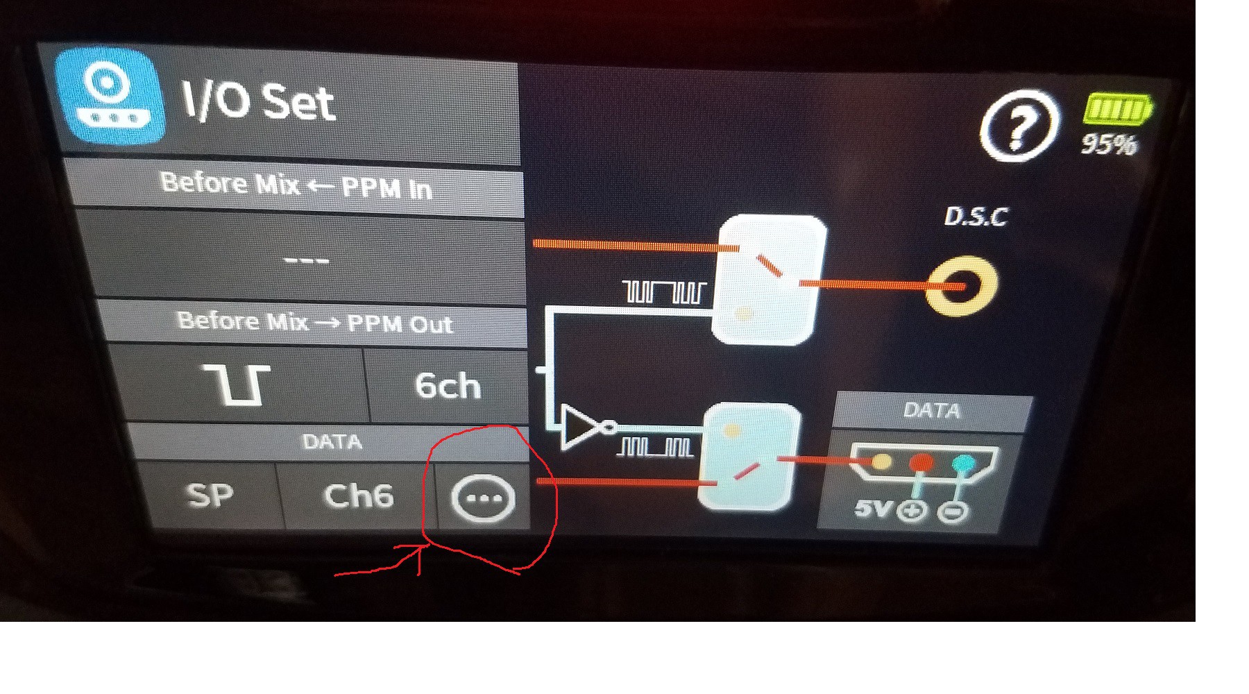
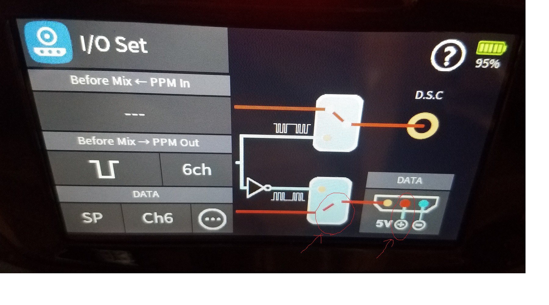
    If using the MZ-32, binding is done via the 'I/O Set' menu as shown in the image below.

    First thing you need to make sure you do is have the DATA output set to 'SP'.  Then make sure you also have power applied to the DATA port.

    (See the RED circled areas on the picture below)

    Next step is to click on the CIRCLE with 3 dots, to bring up the SP (DSM) sub menu...

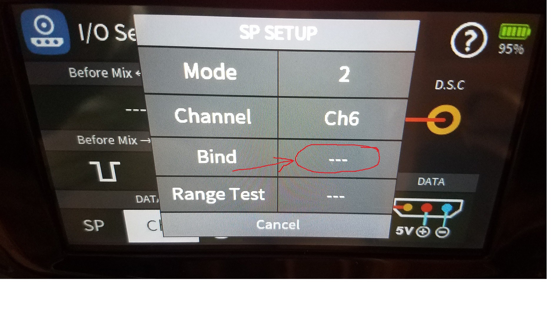
    Next step is to select the CORRECT DSM PROTOCOL, via the 'MODE' menu item on the top left.

    1) MODE 1 ==> DSMX

    2) MODE 2 ==> DSM2


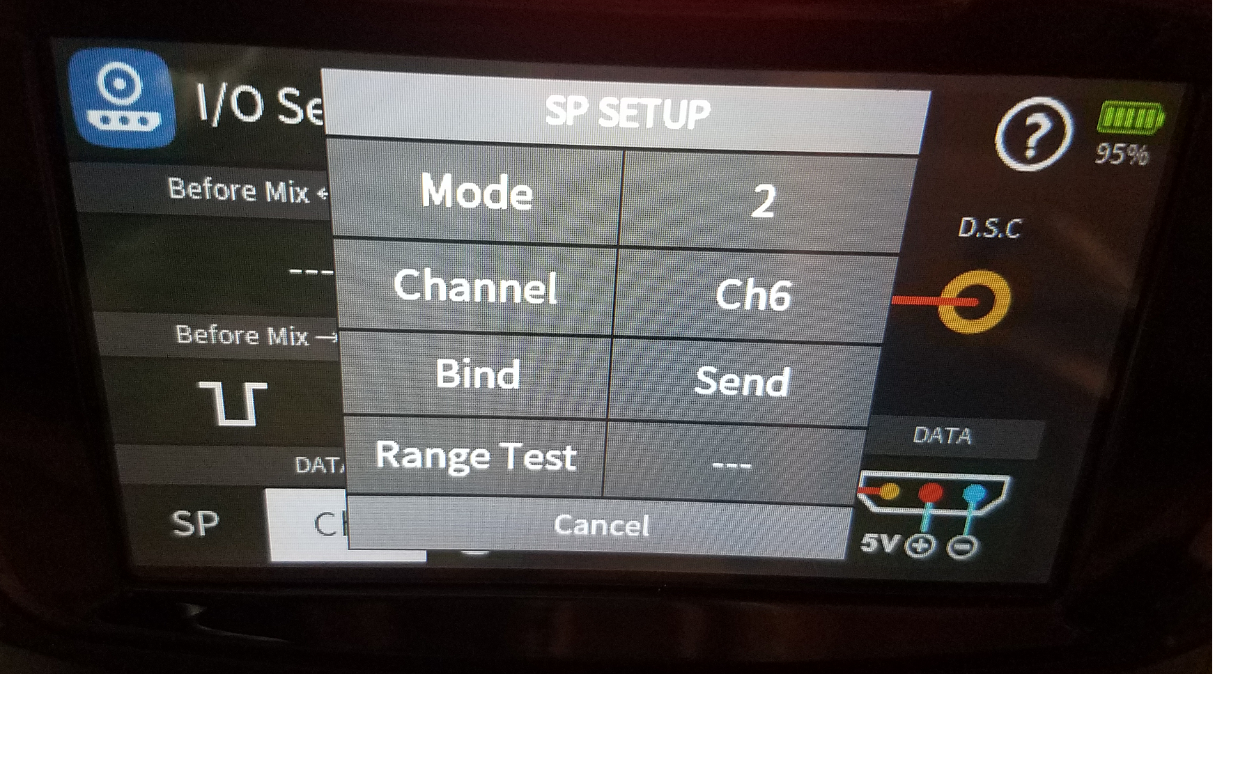
    Click on the '---' button next to the BIND button, this will start the BIND sequence, just wait, it could take up to 30 secs before the bind completes.  If nothing happens, try it again.  If it contines to fail, switch the MODE to the other DSM format and try again


    Below is what you will see once the BIND is initiaited, eventually it will switch from 'SEND' back to '---' once the sequence completes...

    If the BInd completes, just CANCEL out of the menu and fly your model!   If it all failed, you can tap on the middle power rail (above to (+) in the data port below to cut off the 5V power to the module, and then power it back on, and repeat the BIND sequence.

  • MZ-32: Attaching the DSM Module

    PhillyFlyers10/18/2020 at 22:39 0 comments

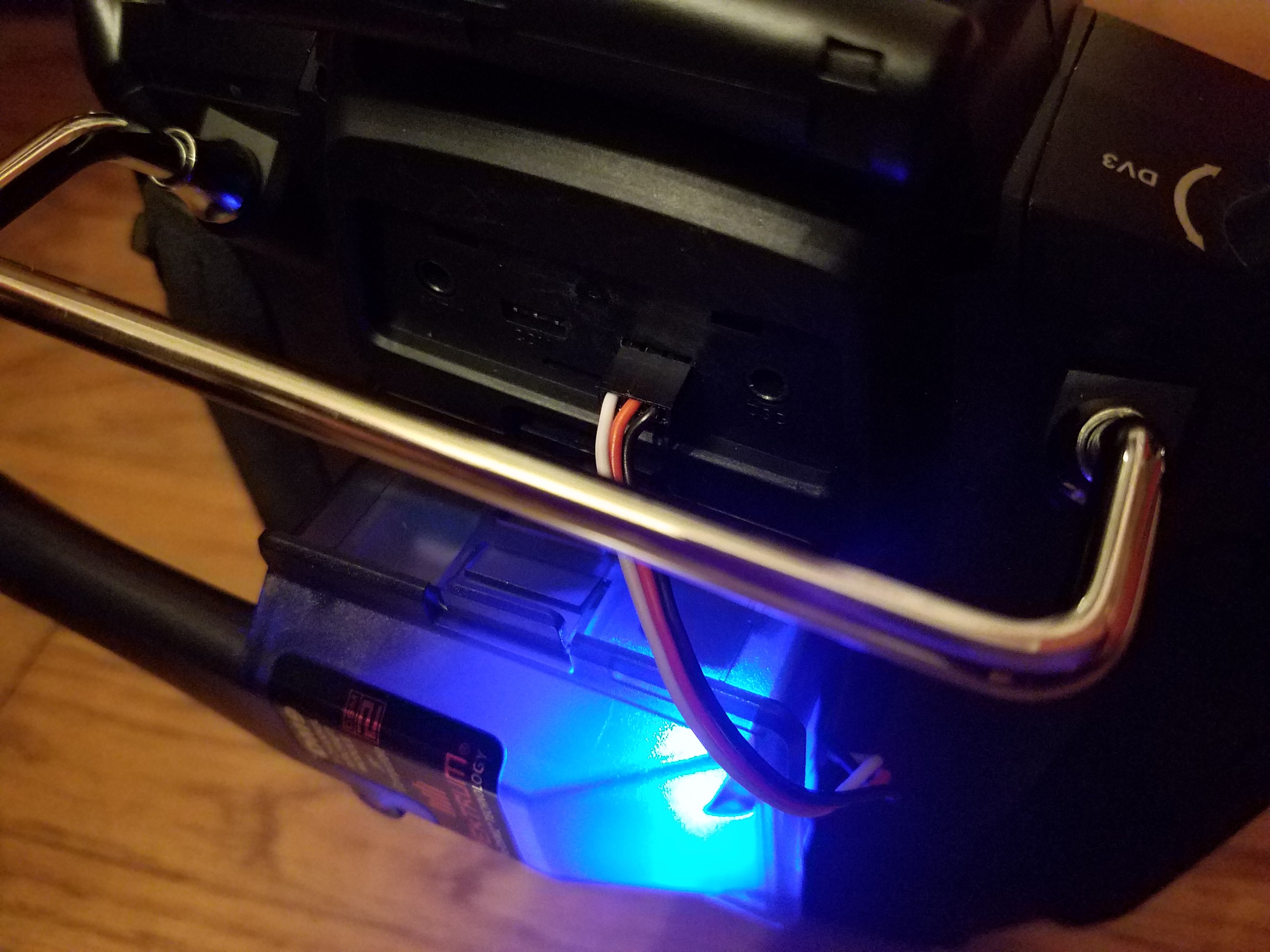
    If using this module on your MZ-32, you want to make sure you connect the servo wire CORRECTLY to the DATA PORT on the back of the Tx.  There is NO notch on the data pin ports to prevent you from installing it backwards!


    Make sure you look at the picture below to see the correct orientation!  The GND (black) wire goes to the RIGHT MOST pin of the 3-pin DATA port!!!!


  • Harvesting an OEM DSM/DSMx RF Module

    PhillyFlyers10/18/2020 at 22:32 0 comments

    In order to build this module, you will of course need to first locate a genuine Spektrum, Horizon Hobby (or other OEM DSM Transmitter.   It seems as if the following models are currently the cheapest to find for DSM RF Modules.

    1)  DX5e  - Spektrum 5 channel radio (Ebay for approx $45 or so?)
    2)  MLP4DSM  - Horizon Hobby (Blade) 4 channel radio  (Ebay for approx $40 or so?)
    3)  DX6e - Spektrum 6 channel radio - (Ebay for at least $150 + )  -- by far the most expensive route

    I'm sure there are others as well that use OEM DSM RF modules, these are just the first 3 I know of..

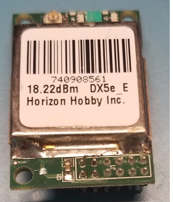
    It's quite easy to unsolder the RF module from the OEM tx board, with a good large-tip iron for plenty of heat, and a nice spool of copper solder braid.  With these two tools, you can easily heat up and suck up the solder around the pins, and then pop out the RF module.  It's normally just held on the top side with some simple double-sided foam gap filling tape.

    DX5e Module - TOP

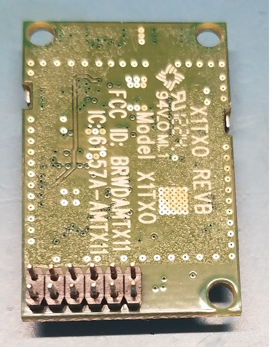
    DX5e Module (Bottom)  -  Part Number:  X1TX0 REVB

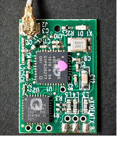
    MLP4DSM Module

  • Assembling the PCB

    PhillyFlyers10/18/2020 at 22:25 0 comments

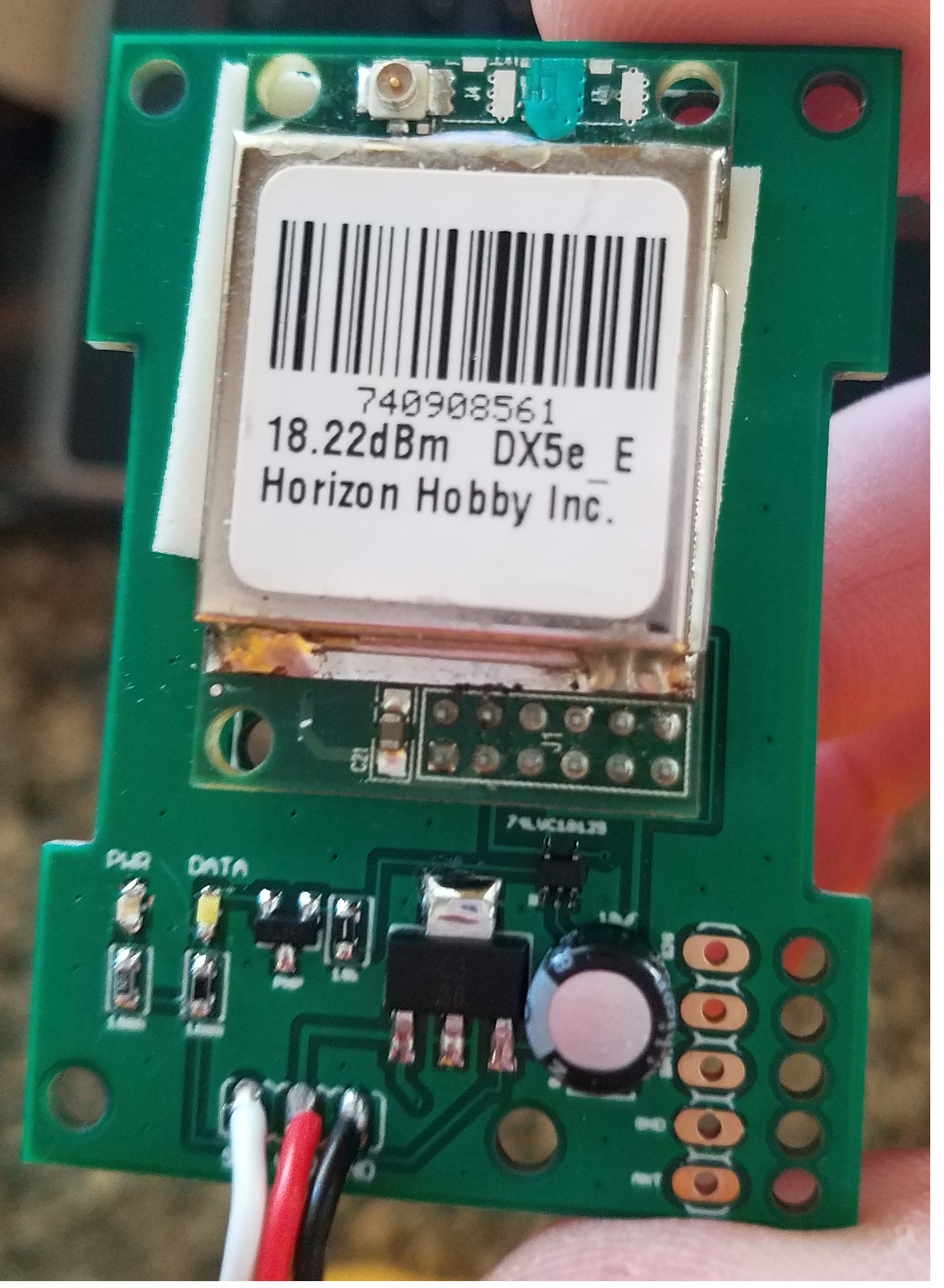
    This PCB was designed around SMT (surface mount components), just to save space... I know these can be a little difficult to solder if you don't have a decent iron with a small solder tip, and some type of desktop magnifier or glasses with magnification.


    I also added TWO LEDs for 'Power' indication and 'Data' indication.  (The DATA LED illuminates when the signal line goes LOW, since it's inactive state is High.  It will appear to essentially be always on because of the 125k baud uart traffic.. but it is actually pulsating, just quite fast!

    I did NOT populate the JR header on the bottom right in my samples shown, as you don't need to buy/solder on this header unless you plan on using this module in another Tx that has a JR compatible module bay (like a Taranis, etc)... ie you do NOT need this header when using the MZ-32.


    You can also build the similar board by John Prikkel (http://johnprikkel.blogspot.com/2014/07/jr-dsmx.html) if you are not comfortable with surface mount components.   Flux paste is your friend!!!


    ** Note **:   I don't really like the original setup where people are using a simple diode + pull-up resistor in order to interface 5v (or higher) from the Tx UART signal to the RF Module signal in.  It works, but not the best way to do it.  I used a simple 74LVC1G125 line driver/buffer that can put out a nice clean 3.3v signal, and take up to 5.5v on the input even while powered from 3.3v.

View all 5 project logs

Enjoy this project?

Share

Discussions

John Prikkel wrote 05/06/2021 at 17:26 point

Thanks for the credit!!!

  Are you sure? yes | no

John Prikkel wrote 05/06/2021 at 17:23 point

You can print this case...

https://www.thingiverse.com/thing:418883

  Are you sure? yes | no

PhillyFlyers wrote 10/18/2020 at 23:18 point

*** As of recently, it seems HH stopped producing these DM9 empty module cases!!  I don't know where to find any more of them, so frustrating!! **

https://www.horizonhobby.com/product/integrated-case-for-jr-compatible-air-module/SPM6817.html

  Are you sure? yes | no

Similar Projects

Does this project spark your interest?

Become a member to follow this project and never miss any updates