-
Improving the UI
11/05/2024 at 08:44 • 0 commentsI got tired of HMUI which assigns the two buttons to update the hours and minutes respectively which required assigning pressing both to Enter Set Mode to avoid accidental changing of the time.
Instead I have moved to MODEUI, where the first button cycles between Normal, Set Hours, and Set Minutes. The second button advances the hours or minutes. There is also a timeout to return to Normal after about a minute of button non-activity. It's the same MODEUI I have been deploying on my other designs.
This required revising the code, but it was straightforward and the changes have been pushed to Github.
-
Retrofitting an RTC, part 2
11/07/2021 at 21:17 • 0 comments![]()
In the last log I coded a bitbang driver for the I2C interface. I now have a working implementation that uses the STM8's silicon. The work consisted of understanding the protocol diagrams in the I2C section of the STM8L reference manual, which is for the STM8L series but also applies to the STM8S series.
Complication arises from the fact the the silicon has a receive pipeline, so some actions have to be taken ahead of reading the data register to generate the correct I2C handshake. Obviously the pipeline exists for speed reasons, for example when reading bulk data from I2C flash memory.
Page 107 of the manual shows different algorithms for the cases where N > 2, N = 2, and N = 1, where N is the number of bytes to read. I also had to consult the example code in stm8s_eval_i2c_ee.c which is a driver for EEPROM. It turns out that it's not sufficient to use just I2C_CheckEvent, one must also use I2C_GetFlagStatus. I have only implemented the N > 2 case as I want 7 bytes from the RTC, so the routine is not general purpose. Bear this in mind if you want to reuse the routine.
The labelled events in the protocol diagram correspond to enum values for the I2C_CheckEvent call defined in the SPL I2C includes. Strictly speaking I should have a timeout on expected events so that MCU doesn't get stuck if an event doesn't arrive. Or perhaps I should use the Watchdog Timer. Anyway I now have two working versions of the I2C driver which can be selected at build time. Since there is still plenty of flash space and MCU power, it makes little difference in practice which one is incorporated. The silicon I2C driver is canonical and doesn't rely on using TIM1 for the delays; you know that the silicon is working as efficiently as designed.
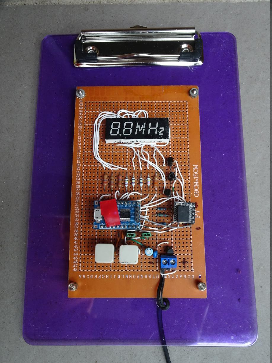
The board was mounted on an A5 acrylic clipboard and I can now finally close off this project.
![]()
Here is the gory receive routine:
void rtc_getnow(void) { // send pointer of 0 I2C_GenerateSTART(ENABLE); while (!I2C_CheckEvent(I2C_EVENT_MASTER_MODE_SELECT)) ; I2C_Send7bitAddress(DS3231ADDR << 1, I2C_DIRECTION_TX); while (!I2C_CheckEvent(I2C_EVENT_MASTER_TRANSMITTER_MODE_SELECTED)) ; I2C_SendData(0); while (!I2C_CheckEvent(I2C_EVENT_MASTER_BYTE_TRANSMITTED)) ; I2C_GenerateSTART(ENABLE); // generates a restart while (!I2C_CheckEvent(I2C_EVENT_MASTER_MODE_SELECT)) ; I2C_Send7bitAddress(DS3231ADDR << 1, I2C_DIRECTION_RX); while (!I2C_CheckEvent(I2C_EVENT_MASTER_RECEIVER_MODE_SELECTED)) ; // read sizeof(now) (7) bytes I2C_AcknowledgeConfig(I2C_ACK_CURR); // ACK uint8_t i = 0; while (i < sizeof(now) - 3) { while (!I2C_CheckEvent(I2C_EVENT_MASTER_BYTE_RECEIVED)) ; now[i] = I2C_ReceiveData(); i++; } // third last byte // wait for BTF while (I2C_GetFlagStatus(I2C_FLAG_TRANSFERFINISHED) == RESET) ; I2C_AcknowledgeConfig(I2C_ACK_NONE); // NAK now[i] = I2C_ReceiveData(); // N-2 i++; // second last byte I2C_GenerateSTOP(ENABLE); now[i] = I2C_ReceiveData(); // N-1 i++; // last byte // wait for RXNE while (I2C_GetFlagStatus(I2C_FLAG_RXNOTEMPTY) == RESET) ; now[i] = I2C_ReceiveData(); // N unpack_time(); } -
Retrofitting an RTC, part 1
11/03/2021 at 00:09 • 0 comments![]()
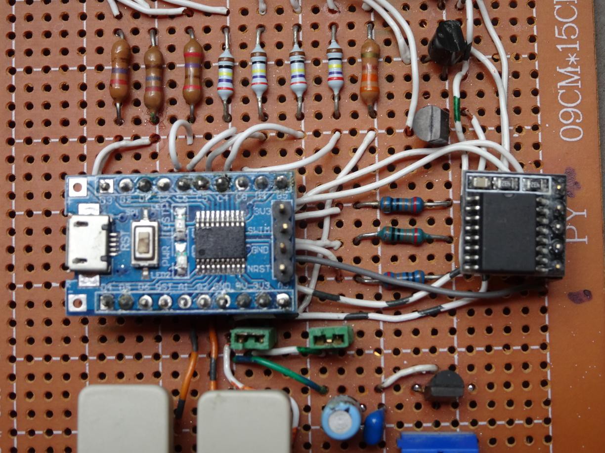
Photo of board with added RTC on right, plugged into 5-pin header.
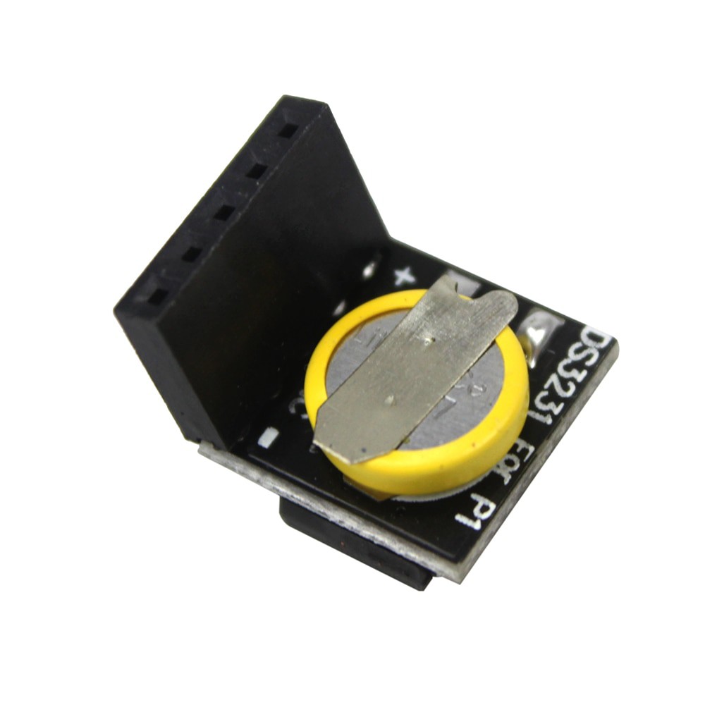
While it is possible to tune the onboard oscillator to give a semblance of accuracy in timekeeping, this is tedious and only really works for a small temperature range. So I looked into ways of improving the accuracy. A DS3231 based RTC will provide a great improvement at little cost, only a couple of dollars.
Fortunately the B4 (SCL) and B5 (SDA) lines on the STM8 board are still available. I added a 5-pin header to the prototype board and connected 4 lines to the MCU. Vdd goes to the 3.3V supply (actually 5V as it's running at 5V, but the RTC can handle that), GND to GND of course, and SCL to B4 and SDA to B5. A couple of 4k7 pullup resistors to Vdd complete the addition.
I started coding using the I2C routines in the Standard Peripheral Library but discovered that the I2C interface is quite comprehensive and needs a good understanding of the various events in the I2C protocol.
So I coded an alternate implementation to get basic experience with this RTC, using bit-banging with the GPIO routines on the same two pins. I thought it should work first go after a clean compile as the code had been tested before on other processors. However I was over-optimistic as there were a couple of things I didn't anticipate. The first is that I had been spoiled by the 8051 pins which have weak pullup and thus don't have to be explicitly switched between input and output. In places in the protocol, one has to switch the SDA pin to input. The second is that the GPIO_ReadInputPin routine doesn't return 0 or 1, but rather 0 and !0, the difference being anything non-zero qualifies as !0. In particular the routine returns the bit in the SDA position which is B5 or 2^5. So one part of the byte assembly routine has to be changed from
data |= GPIO_ReadInputPin(GPIOB, GPIO_PIN_5);to
data |= GPIO_ReadInputPin(GPIOB, GPIO_PIN_5) ? 1 : 0;Being able to observe the program in action using PlatformIO was a great help debugging.
I will get back to coding the native I2C implementation after digesting the I2C section of the STM8L reference manual, which is for the STM8L series but also applies to the STM8S series.
A remark: If you had modified the design to accommodate a more conventional 4 digit display, then the only line left for driving the 4th digit is D1 (SWIM) which means you have to decouple that line for flashing or debugging. Other solutions are to get a STM8 with a larger set of GPIO lines, or to use a decoder or shift register to drive the digits so that you don't need more than 2 or 3 digit outputs.
-
Small tweaks to firmware
10/06/2021 at 09:54 • 0 commentsI've made a couple of small tweaks to the firmware.
- The buttons can be accidentally pressed and the time changed. Now you have to depress both buttons together to enter set mode and the display will blank 0.5 seconds. After 8 seconds of button inactivity after setting, it will exit set mode.
- The DDS adjustment can be specified in the Makefile, instead of editing tod.c
I doubt if anybody else has this clock but you may find the techniques useful.
 Ken Yap

