Altough I'm not fully satisfied with the current top design I'll start buidling the 2nd Prototype which I've showed in the last log. The hole top cover will be printed with a normal FDM-printer with a built plate area of an A4 (210x297mm) and therefore it's little bit tricky to cut this large part in different pieces.
The different sections:
The top cover is split up in two main halfs. The half section is split up again in six different segments. The parts are mounted and secured with rods and bolt-on segments.
Max-out the build volume of my 3d printer
The parts fit quite tight inside the mentioned build volume of 210x297x200 (lxbxh) but It should work for a first top cover.
I've tried to design the parts in a way that the need of support structures is a low as possible to save filament and reduce print time. The latter should be around 120h of print time which is enormous compared to my usual 3-8h prints.
Building/Printing the first parts
The first four parts of the topcover are printed and mounted on the printer. So far so good and maybe the design grows on me over time so I don't have to design a completely new one
I wasn't happy with my initial top cover designs but I want one since day one. It's quite cumbersome to clean or remove the dust every once in a while from all the motion parts and connectors on top so I want mainly top cover to solve that. Of course it should help with chamber temperatures but to be honest that's not my main goal anyway (to print like in a chamber with +100°C)
The new top cover should consist of seperate portions which can be sticked/glued together. I've designed to not use sheet metal parts because I want to itegrate some latches/hinges in the front and backpart to easily access the top area of the printer to maintain, check tools or change tools.
This cover is stil a mockup to play with the design before I'll fully redesign the top cover with individual segments. Of course the acrylic panels are missing in the design as well but in the end there will be 5mm acrylic side panels as well.
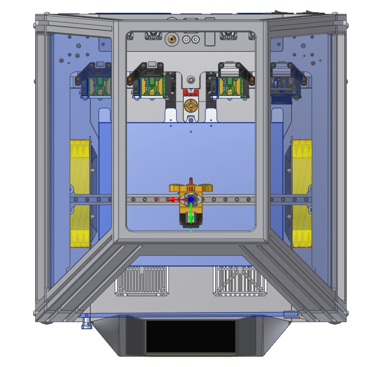
Top-view:
I tried to include design elements from the mainstructure and merged it to the top. One example is the groove which represents the 3060-Extrusions from the base-assembly.
Mockup - almost completed
In the end my main goal is that you can open the front panel of the top cover (hinged) but I still have to think of the propere hinge type for that. Maybe I'll design my own with a rasting-feature to ''lock'' the front panel in place.
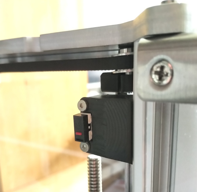
Because I'm not a big fan of sensorless homing I implemented mechanical endstops for the x and y axis right from the beginning. The y-axis endstop is directly implemented in the idler-belt-tensioner and therefore in the same plane of the xy-motion system. The x-axis however was screwed to the extrusion of the frame what I never really liked because of the interface and the added error possibility when the coreXY-plate is removed and assembled again.
The old x-endstop:
I also didn't like the way it looked with the large fdm-part and the micro switch clearly visible from all sides.
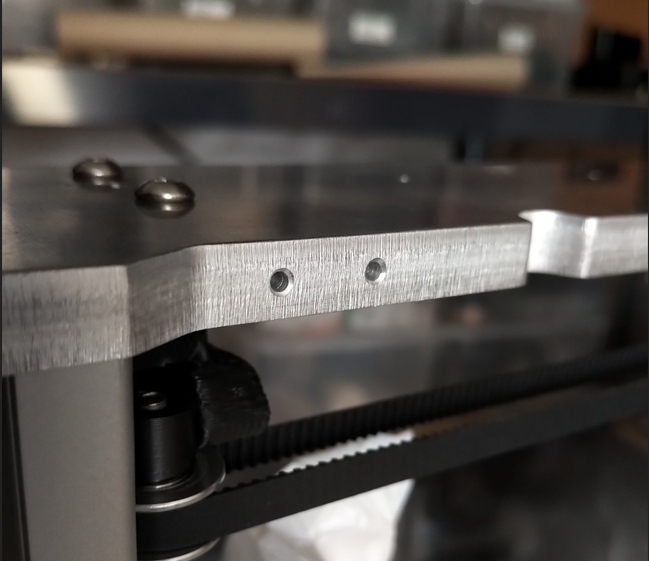
The new endstop:
For the new endstop design I had to drill two 2mm boreholes for two M2-threads.
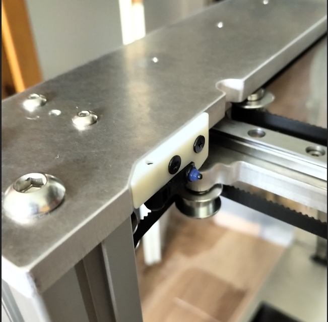
After the taping I've installed the endstop holder (SLA-printed, printed on the Form 1+) with an OMRON switch installed. Because the new endstop is on the opposit side (x-direction) I had to rewire the endstop cable and re-configure the Duet firmware.
Now I can easily disconnect the endstop and take off the coreXY-plate without worrying about re-calibration or re-checking the position of the toolhead relative to the printbed.
To improve the quality of the CHANGER I always wanted to use SLA-Parts for a.) better appearance without a lot of post processing (grinding, painting etc.) and b.) better dimensional accuracy.
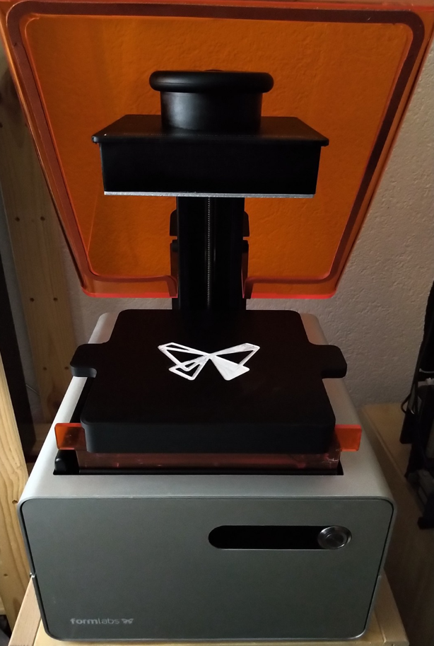
The acquisition - Form 1+ :
Altough this printer is quite ''old'' and uses standard galvos (galvanometer) instead of a faster LCD it prints quite fast and accurate. Because of my work with LiDAR's in the industry I'm quite familiar with the mechanics and therefore now how to handle, maintain and repair such optical systems. I've quickly designed and printed a VAT-Cover to better handle the fumes when not in use.
First successfull prints for the CHANGER :
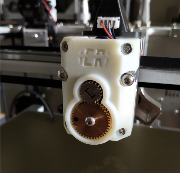
For the first practical print with my Form 1+ I designed/adjusted the toolhead cover for sla printing and implemented the shorter CHANGER-Logo to test the resolution and finer details.
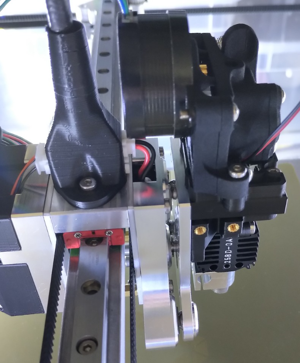
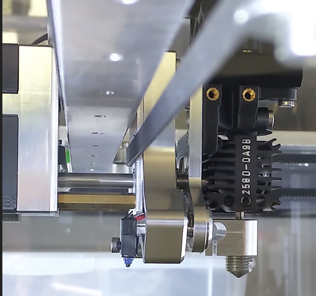
Because of the compact design the Dyzend needs some adjustments to work with the coupler. I've wanted the center of mass of the printhead as close as possible to the actual toolhead to minimize the leverage and therefore the play of the tool due to tolerances in the carriage (X-Axis)
I did a small cutout/drillout for the coupling mechanism of the toolhead otherwise the coupling would not work. Because I didn't want to drive to my cnc mill I've quickly used a ø5mm drillbit and a file to make it work.
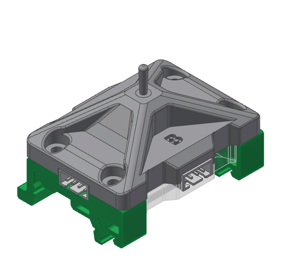
Because of the limited stepper drivers of the Duet 2 Wifi + Duex5 I want to use the same stepper driver for the bowden stepper as well as for the directdrive stepper of each tool. This works fine because you have to decide and can't use both in the same tool. You insert either a directdrive tool or a bowden tool. Therefore you just have to switch between the steppers and change the config of the stepper driver (E-Steps, Direction and Current).
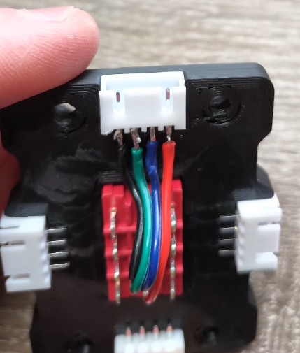
For wiring there isn't much space left but with some sure instinct it workes just fine.
I've used three instead of two outputs to connect the direct drives either left or right for easier handling and cable management. the top is for the direct drive output. The bottom is the input from the duet driver.
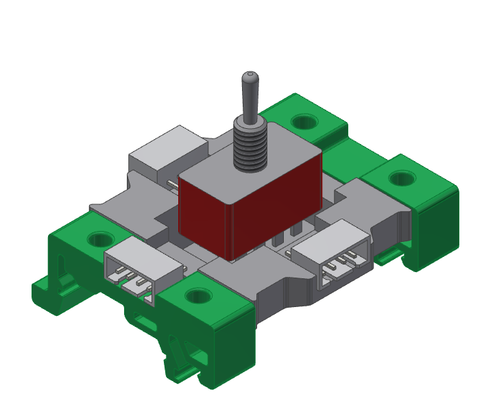
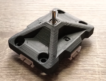
The final switch fully assembled and soldered...
Future Idea:
The physical switch is just for initial testing to proceed with the hole bulid of the CHANGER. In the end I'll design a pcb to handle the switching process. For safety reasons I'll detect the current in the coils to determine if the stepper is in use before switching between bowden and directdrive. The pcb sends automatically the stepper-off comand to the duet to deactivate the driver before switching to protect the driver. Just for the moment I'll proceed with the physical switch.
I'm currently trying to get a proper cover done to fully enclose the printer. My main goal is a universal topcover with full accessibility to all relevant functions of the printer (tool-change, belt tensioning, watercooling outlet, air-outlet etc.) without loosing the industrial look of the printer. My least favorite option will be a acrylic-extrusions assembly.
My current designs:
Design 1: Bent-acrylic (illustration, not finished):
This design is minimalistic but functional. The backside consists of the backpanel and a latch/hinge so you can easily access the tools (not implemented in the design yet). The same principle could be applied to the front panel as well but it would work with glued/screwed and therefore fixed front panel as well.
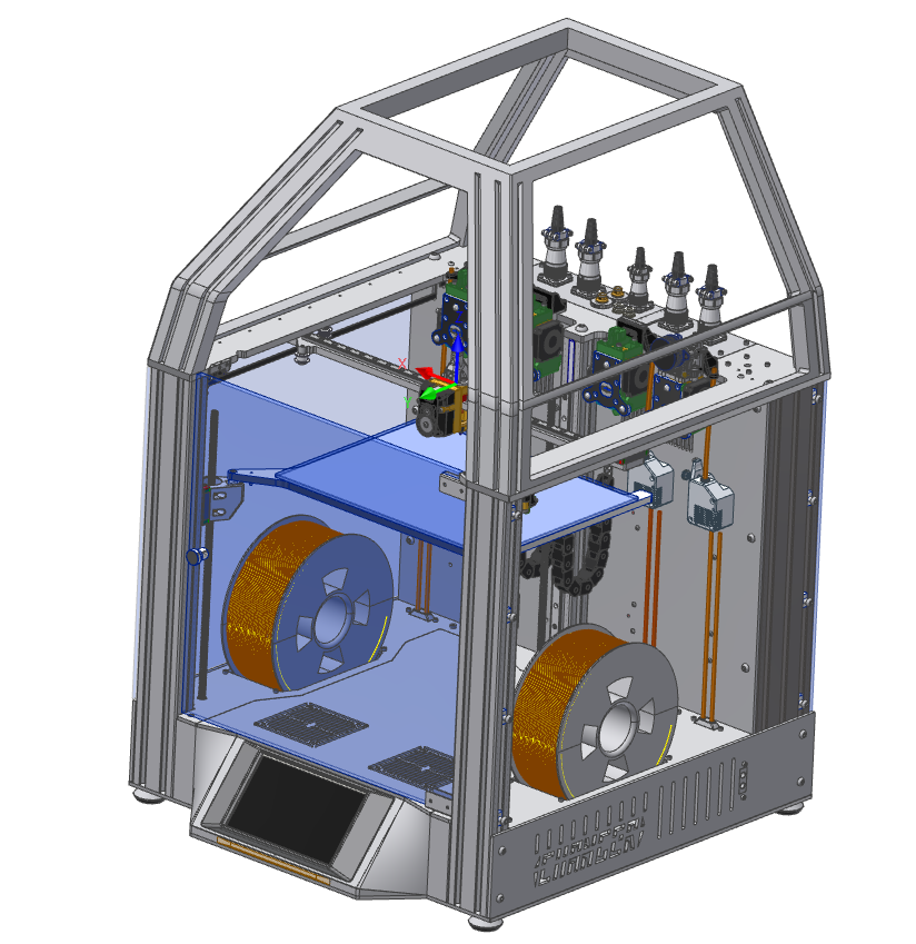
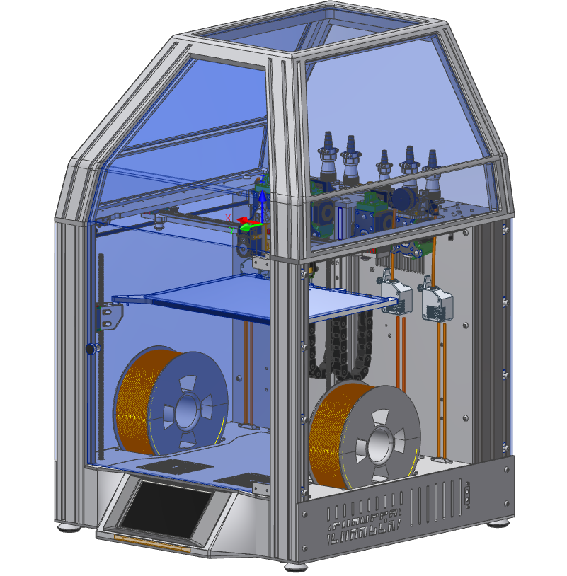
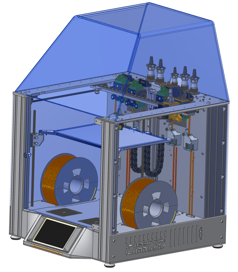
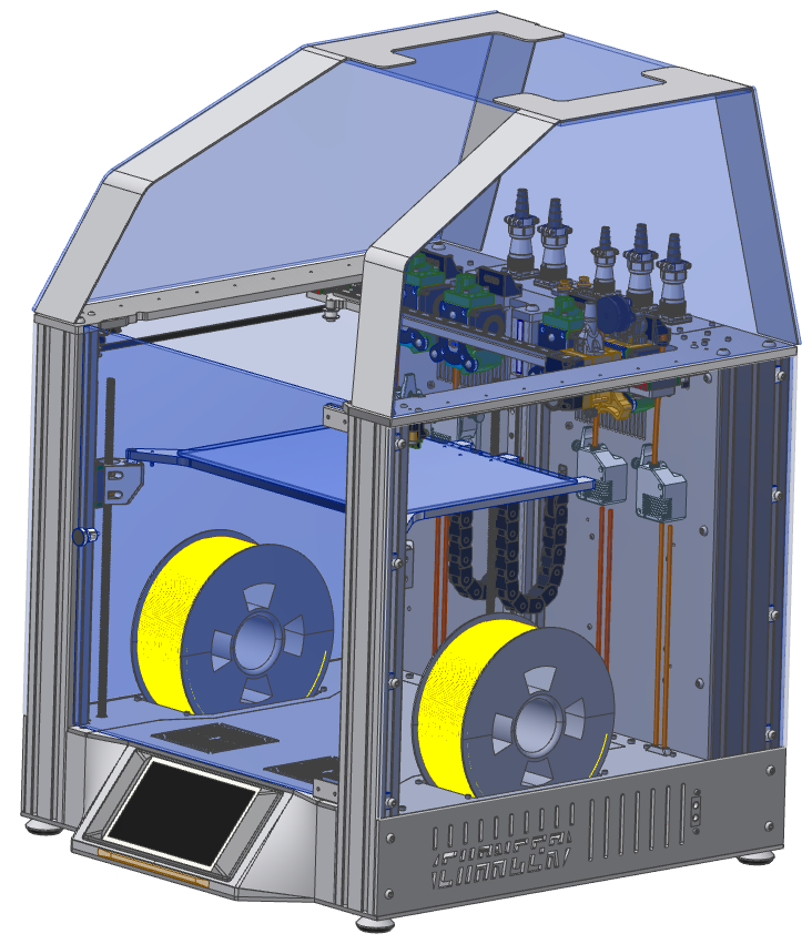
Design 2: Aluminium-construction (illustration, not finished):
This design is more complex but still fully functional. The mainframe consists of two bent aluminium sheets which gives this assembly the rigidity. The flat top panel/sheet is fix mounted on to the mainframe/two aluminium sheets. The back and the front will get hinges as well so you're able to access the toolhead from the front and the tools/tooldocks at the back by open up the panels. You could even get rid of the first bend and bend it more like in the first design so you can simplify the bending geometry of the two aluminium sheets.
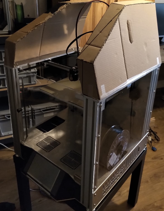
C.A.D of Design 2 (Cardboard Aided Design ;) )
I've started bulding a first mock-up of the cover to see the impact of the design over time. Actually the cardboard-Design existed before the actual CAD-Model because I wanted to get a feeling for the important design parameters of this cover design.
Your opinion? / Conclusion
I'm still kinda undecided about the direction of the top cover. The top cover is key to the overall appearance of the printer and I want the printer to look quite industrial and therefore I'm struggling with some quick&dirty covers. I even bult a cardboard cover of the 2nd design to see if the design ''grows'' over time. What's your opinion about the design direction of the top cover for such a motion system / toolchanger? Let me know your thoughts in the comment section.
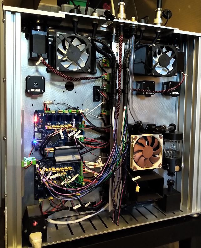
I was finally able to finalize the backpanel to enclose the electronics at the back. In the meantime I've worked on the tools as well and ordered some directdrive extruders as well as a new hotend for higher temps.
Forex for lightweight backpanel:
A good friend of mine recommended the use of forex for the backpanel as alternative to the classic pmma-panels. At first sight I was quite hesitating but I'm glad that I tried the forex panel. Forex panels are rigid foam sheets made out of pvc and therefore are slightly lighter as PMMA (acrylic) panels. The texture is a little more rough but shines slightly. I think it is a little more scratch resistant which is quite nice for a panel which comes off from time to time.
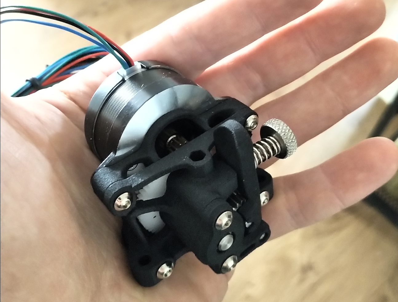
For better appearance I've quickly designed some grids/covers for the outlets and inlets. Small directdrive tool:
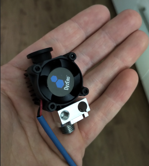
The quality seems fine and the form factor is quite nice for the limited space of the CHANGER-Tools. For the hotend of the first directdrive tools I wanted to use the DyzEND-X Hotend (DyzEnd-X Hotend 1.75mm - Fast Printing - DYZE DESIGN)
I'll need to finalize the actual tool and print the first holder to test the directdrive hotend on the CHANGER. I'll post the first results as soon as I'm able to continue the work on my printer.
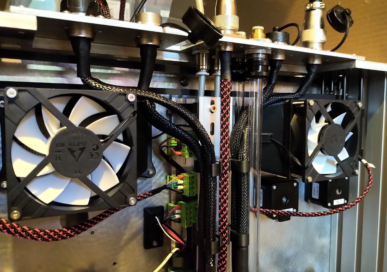
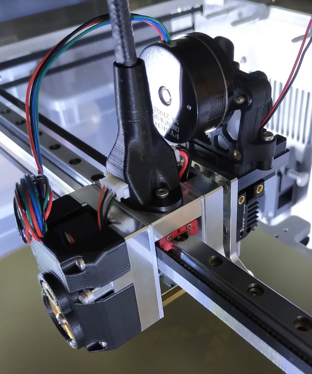
I've finished the wiring harness for the tooldocks. I've tried to keep it tidy but with the chance to quickly remove the individual tooldock-harness for easy maintenance.
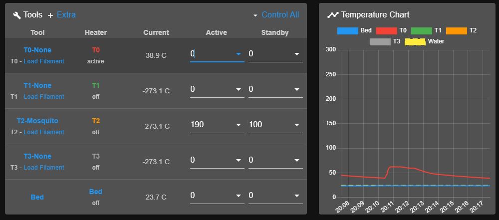
Configuration:
I've configured all the fans (Heatsink, Partcooling etc.) like already mentioned in the last project-log. I added a 10K Temp.Sensor for the watercooling cycle so I'm currently using all of the thermistor inputs on my Duex5. You can add all of the Temp. Sensor to the temperature log in the Duet Webcontrol/-server which looks like this:
Because I've installed just one working tool there is only one correct temp. value for the tools 0 to 4. The temperature of the watercooling loop is monitored as well.
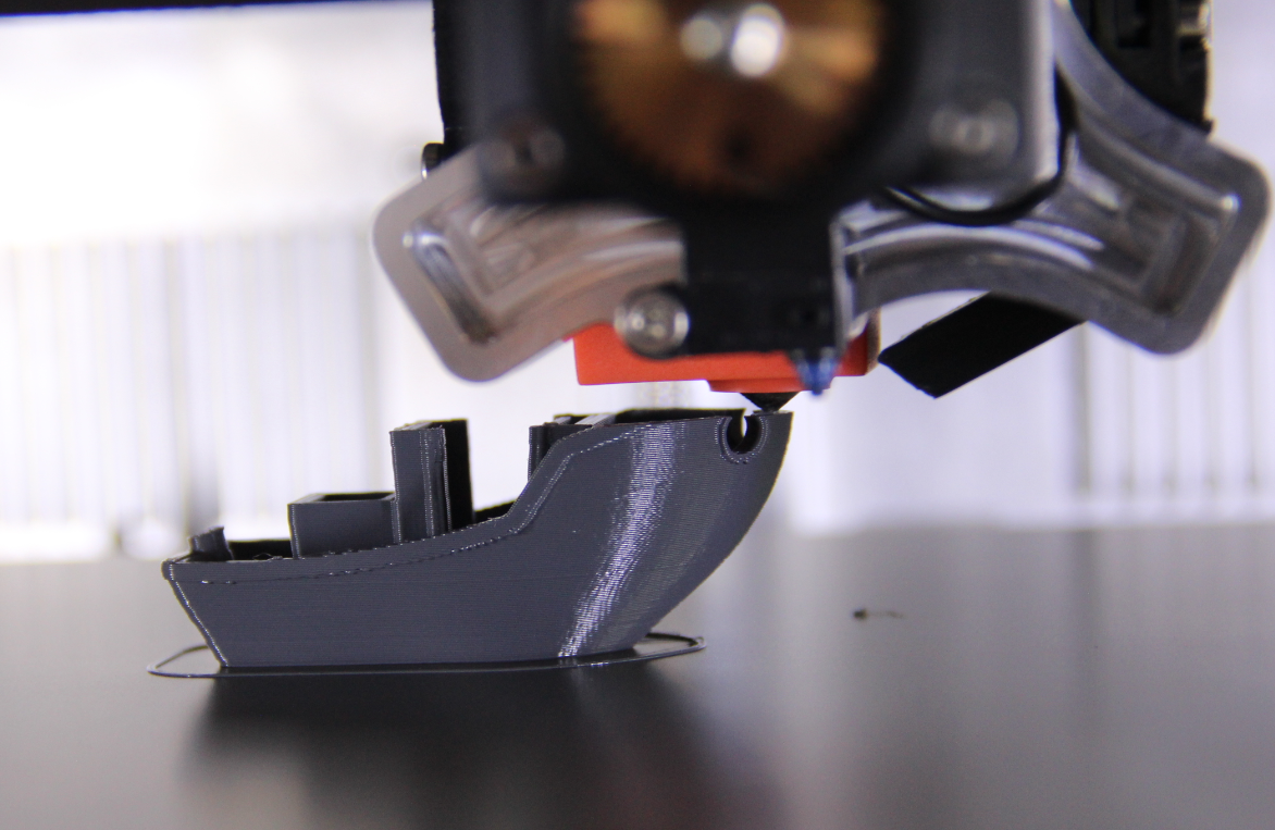
In my first Benchy-attempt I noticed the heavy cooling issues with my mosquito-Bowden tool. Despite that the printer performed as expected. Before I build more tools I want to adress the cooling issues with the first tool so I can implement the cooling Design (Fan powered) in my next tools. I haven't tested the integrated airpump because I don't want to use it for my PLA-Bowdentools.
If you compare the Airflow to Weight ratio the best options are:
Delta BFB04512 (45x45x12mm) with 0.0075 [m³/min] /gr
Delta, BFB0412 (40x40x10mm fan) with 0.007 [m³/min] /gr
NMB, 4515 (45x45x15mm Turbofan) with 0.005 [m³/min] /gr
Micronel, D243 (impeller-Design) with 0.002 [m³/min] /gr
Decision for first Bowden-Setup:
I've redesigned the Bowden-tool and used a Trianglelabs Dragon-Hotend and sticked to the 40x40x10mm fan because of the good airflow to weight ratio and re-oriented the benchy on the buld plate so the fan blows to the overhang section at the front.
With the new setup I was able to print a proper benchy. For now I'm quite happy with the result and I will start testing with some genuine GT2 belts and start machining the currently 3d-printed belt tensioner so it can withstand higher tension forces.
 Simon Wirz
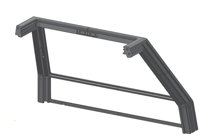
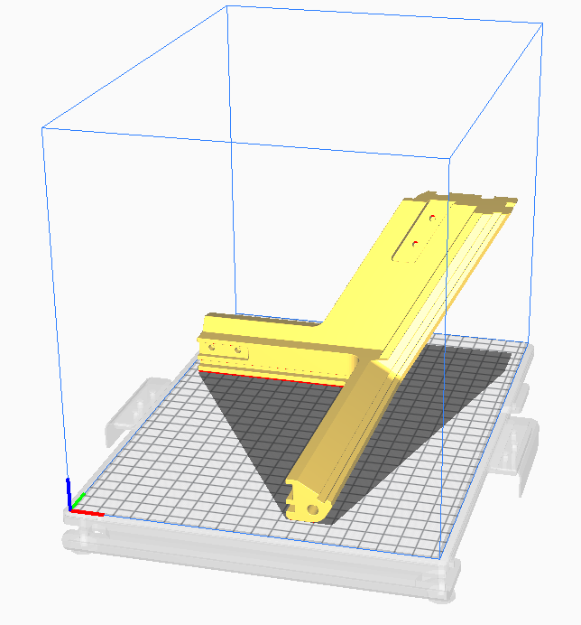 The parts fit quite tight inside the mentioned build volume of 210x297x200 (lxbxh) but It should work for a first top cover.
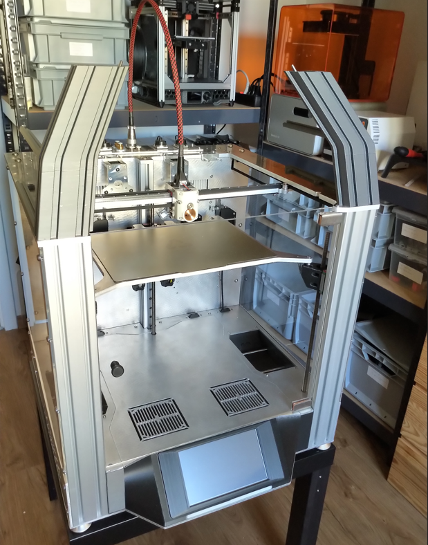
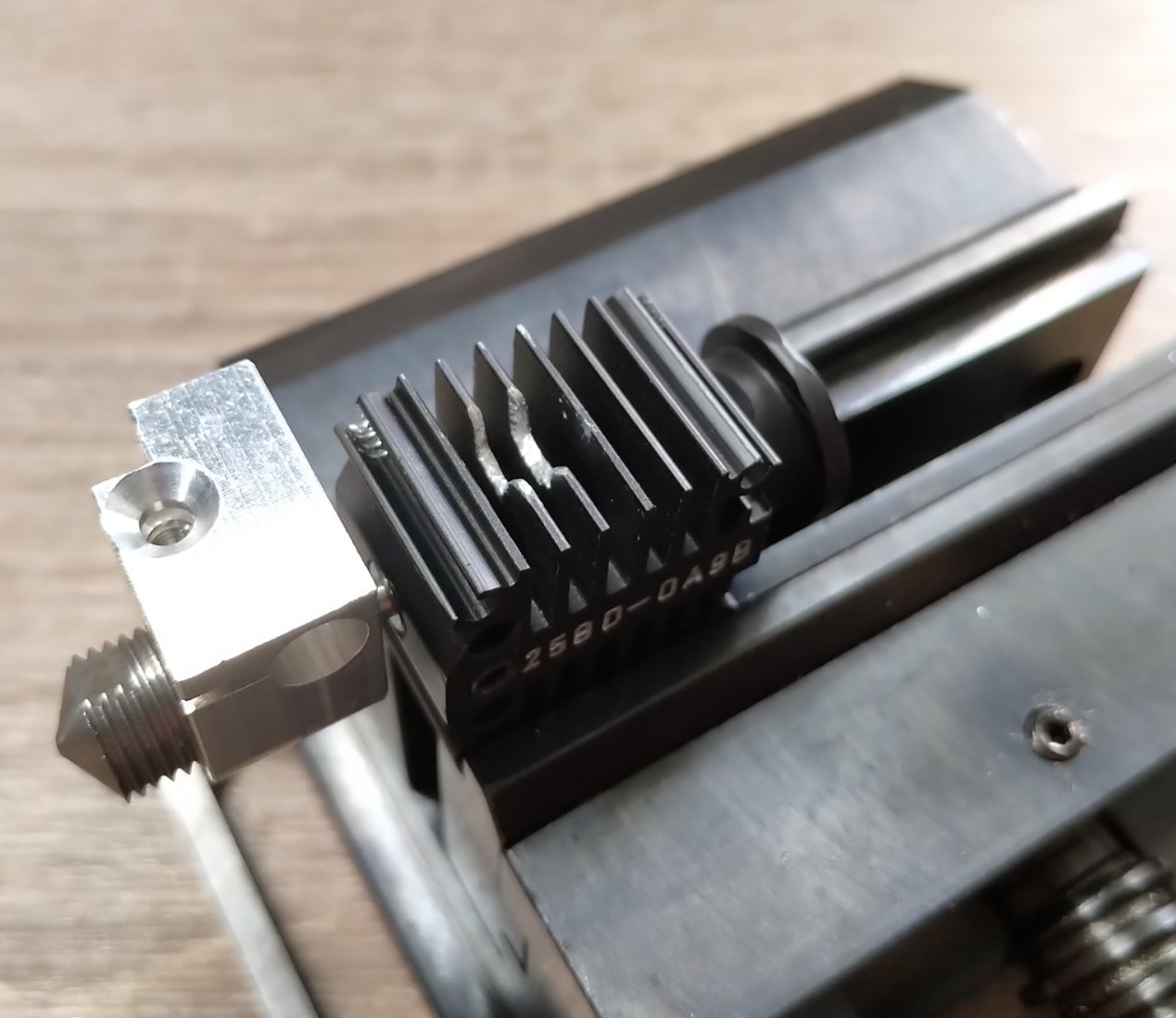 I did a small cutout/drillout for the coupling mechanism of the toolhead otherwise the coupling would not work. Because I didn't want to drive to my cnc mill I've quickly used a ø5mm drillbit and a file to make it work.
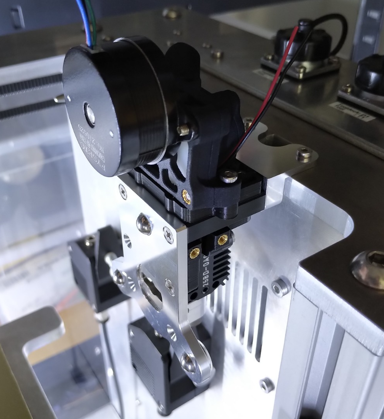
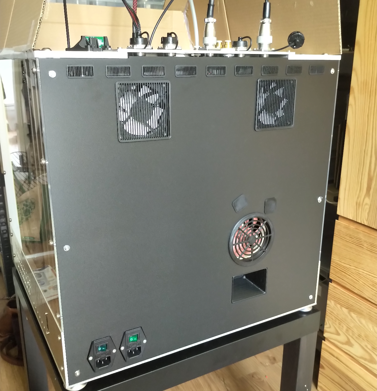 For better appearance I've quickly designed some grids/covers for the outlets and inlets.