fjkraan
-
ROM-Emulator simplified diagram
08/09/2024 at 11:58 • 0 comments
Here a diagram showing how the ROM-Emulator works. In operational mode, the RAM chip is connected through the buffers and POD converter to the socket of the target board. All the Arduino pins connected to the RAM are tri-stated, so the processor on the board sees the contents of the RAM.
When the Arduino accesses the RAM, the buffers are tri-stated, isolating the RAM from the board. The processor would see FFh in the memory region addressed by the socket. The Arduino can now fill the RAM with data received from the PC, or change it with its internal commands.
-
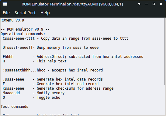
Simple GUI program for configuration & uploading
07/21/2024 at 10:45 • 0 commentsJust now I added a simple python3/wxWidgets program to the GitHub page (https://github.com/electrickery/ROM-emulator?tab=readme-ov-file) for those with a command-line allergy. It is still quite rough, and only really tested on my Linux system, but should work for Windows and MacOS too, as it is based on the wxTerminal.
It assumes versions of Python3 and python-wx are installed on the system.
![]()
It is very basic, but it finds and configures the serial port at startup, and has a nice File > Download Hex file menu option. It even lists the help text with Help > Help!
Some issues in version 0.1:
- Only tested on my MxLinux.
- It adds more linefeeds than needed to the ROM Emulator output
- It converts all typed text to upper case (seems to be a wxWidgets bug)
- Hex file offsets should be entered into the terminal, no nice field and button (yet)
-
Minor updates
02/09/2023 at 09:24 • 0 commentsThe hardware and software works good enough for my needs, so only small updates:
- Added combined echo and CR support for terminal mode,
- Replaced the python3 romEmuFeed program with a newer version with better argument handling and made the tty port an argument too.
-
Arduino firmware and Python upload program update
02/05/2022 at 20:22 • 0 commentsUpdated the Arduino firmware and Python upload program, to reliable upload hex files produced by z80pack/z80asm. New versions at https://github.com/electrickery/ROM-emulator.
-
Improved 2716 emupod wiring
12/21/2021 at 14:19 • 0 comments2716 28p cable header 24p socket header remark 1 A14 - connect to GND 2 A12 - connect to GND 20 CS* 18 CE* 22 OE* 20 OE* 21 Vpp connect to Vcc 23 A11 - connect to GND 26 A13 - connect to GND 27 WE* * connect to Vcc or the WR* signal 28 Vcc - not connected -
ROMEmu assisted workflow
09/23/2021 at 16:19 • 0 commentsMy primary usage for the ROMEmu is writing and testing software for simple a Z80 SBC, the Multitech MicroProfessor MPF-I. The ROMEmu allows me to minimize the number of 'moving parts' while developing.
One time setup:
- connect the ROMEmu to the target system using a ROM or RAM socket mapped somewhere in the address space. For a startup ROM the SBC should be halted.Then it is mainly this iteration:
- Edit and assemble some code for the destined address in the target memory space on the cross-assembler PC,
- Upload the hex-intel file to the ROMEmu with the python script,
For example 'python3 romEmuFeed.py lcdtest.hex 2000' The second argument compensates for the address difference between ROMEmu and target system
- Execute the program in the ROMEmu memory. For the MPF-I this means 'RESET'; 'ADDR' 2000; 'GO',
- Evaluate the program and restart at the edit step. -
EmuPod & SocketAdapter information
08/02/2021 at 10:59 • 0 commentsThe EmuPod and SocketAdapter boards adapt the flat cable to a specific socket. The flatcable carries all signals from the 32kByte RAM, a 62256/D43256. The EmuPod transforms those to mimic the ROM signals. The SocketAdapter adapts to the physical socket form.
Each target ROM has a different pin layout, so expect to reserve a set of these boards for each ROM. Not all pins will change, thanks to the JEDEC standard, but some will. The ROMEmu optionally also allows writing to the RAM if a write signal is available, complicating the configuration somewhat. Unused address lines are connected to GND, to address the lower area of the RAM. An unused write signal is tied to Vcc.
Adding headers to the EmuPod:
- the cable header is placed on the component side, the side with the white silk-screen markings
- the socket adapter header is placed on the solder side. This to prevent the signals to be mirrored for the SocketAdapter. If you use a direct flatcable-socket adapter, then place the socket adapter header on the component side too.
SocketAdapter remarks:
- the header from the EmuPod is placed on the component side, the pins to the socket on the solder side. Make sure you use special socket headers with round pins, the usual flatcable header pins are to big. To protect the socket header pins from breaking off (and having you to resolder the header!) place at IC-socket on them. These are much easier to replace.
Some EmuPod wiring configurations. Only the 2532 one is properly tested!
Note: the cable header numbering used is the not the standard Odd-Even order, but a Counter-Clock-Wise order, the same as used for I.C-sockets.
This is for the 2532 EPROM socket (EmuPod24/SocketAdapter24):
28p cable header    24p socket header    remark
    1  A14                -             connect to GND
    2  A12                -             connect to GND
   20  CS*              20  CE*
   22  OE*              22  OE*
   23  A11              18  A11
   26  A13                 -            connect to GND
   27  WE*                 *            connect to Vcc or the WR* signal
   28  Vcc                 -            not connected
     -                  23  Vpp         connect to Vcc
This is for the 2732 EPROM socket (EmuPod24/SocketAdapter24):
28p cable header    24p socket header    remark
    1  A14                -             connect to GND
    2  A12                -             connect to GND
   20  CS*              20  CE*
   22  OE*              22  OE*
   23  A11              21  A11
   26  A13                -             connect to GND
   27  WE*                *             connect to Vcc or the WR* signal
   28  Vcc                -             not connected
This is for the 2716 EPROM socket (EmuPod24/SocketAdapter24):
28p cable header    24p socket header    remark
    1  A14                -             connect to GND
    2  A12                -             connect to GND
   20  CS*              20  CE*
   22  OE*              22  OE*
   23  A11              21  A11
   26  A13                -             connect to GND
   27  WE*                *             connect to Vcc or the WR* signal
   28  Vcc                -             not connected
This is for the 2764 EPROM socket (EmuPod28/SocketAdapter28):
28p cable header    28p socket header    remark
    1  A14              -               connect to GND
   26  CE2                              not connected
      -               26 NC             not connected
   27  WE*              -               connect to Vcc or the WR* signal
                      27 PG*            not connected
This is for the 27256 EPROM socket (EmuPod28/SocketAdapter28):
28p cable header    28p socket header    remark
    1  A14              27  A14
     -                   1  Vpp        not connected
   26  A13              26  A13
   27  WE*                *            connect to Vcc or the WR* signal
This is for the 62256 RAM socket (EmuPod28/SocketAdapter28):
28p cable header 28p socket header remark 1 A14 27 A14 26 A13 26 A13 27 WE* 27 WR* -
Fix for ROM Emulator 1.1 Mega boards
07/07/2021 at 06:58 • 0 commentsThe 1.1 board did seem to work in some conditions, but wasn't really universally usable. This is a fix for the board, making it compatible with the 1.3 design. I didn't need more boards, so haven't really ordered and build any 1.2 or 1.3 for testing. The modification for 1.1 described here does work.
- replace the 74LS02 at U2 with a 74LS27
- cut trace to U2-1
- cut trace to U2-2 (component side)
- cut trace between U2-6 and U2-7
- cut both traces to U2-12
- cut trace between U2-8 and U2-9
- connect U2-9, U2-10, U2-11 to U2-7 (unused port)
- connect U2-1, U2-2, U2-13 to U2-6
- connect U2-4 to U6-7 (H1, buffered board OE*)
- connect U2-5 to U5-1 (H0, buffered board CS*)
- connect U2-12 to U3-19 (board read)See the boardPatch1.1to1.2.jpg image
-
ROM-emulator application
12/26/2020 at 21:08 • 0 commentsAn usage for the ROM-emulator just went live at GitHub: https://github.com/electrickery/Z80SerialMonitor
ROM-emulator
Emulate a small size ROM with a RAM and Arduino with Intel-HEX interface