Vector Drawing Machine, Number 3
Background
Being an Engineer, I have always been drawn to the Russian pragmatic method of naming new products. While some idiotic Western Marketeer might name a small CRT based gaming machine ‘The Vectormatic Score-Master 3000’, the Russians tend to use something more meaningful, and since this is attempt three at a vector-based display system, they might call it the Vector Drawing Machine, Number 3. So that is how this project became known as the VDM3. Fifteen–love, Engineering vs Marketing departments.
Many years ago, my imagination was immediately caught with the idea of using a small (oscilloscope) CRT as a method of displaying an analog clock. As well as the possibility of an æsthetically pleasing and gentle display, there is also the utter ridiculousness of such an undertaking. The thought that a small chain of mechanical linkages being replaced with a microprocessor controlling a pair of high voltage differential amplifiers, as well as an independent EHT (is 1000V EHT ?) power supply just to (roughly) tell-the-time is just a bit daft. The whole project was quite a monumental undertaking when one also considers all of the work associated to generate the process steps that end up with a nice looking device, along with the reams of associated design information.
One of the other attractions of this project was the sheer breadth of activities associated with the design. None of the activities were particularly onerous, but taken as a whole, the integration phase of such a project is the usual time to discover any inter-disciplinary weaknesses.
This article is not intended as a construction project, but there may be some design ideas of processes that spark some interest in unexplored, dark alleyways.
Summary
The enclosure is fabricated in two parts using from laser-cut MDF. The top section houses the CRT display readout, HV power supply, deflection and associated controls. The lower section houses joystick, pushbuttons, processor, and low voltage power supply. The rear of the lower section has a DC power socket, as well as a mini-B USB connector. Top and bottom sections slide together. The two are halves are locked together by the Joystick/User Interface panel dropping into place.
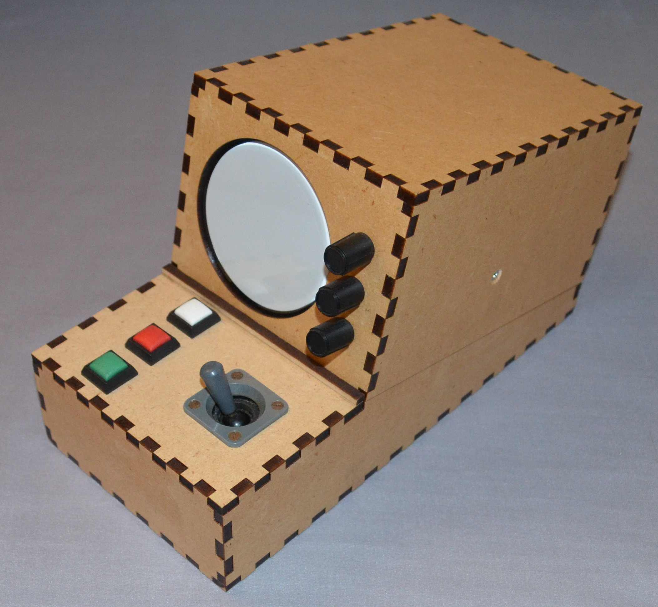
Assembled unit
CRT
The CRT is a D7-16G, just over 76mm diameter, 160mm long and designed for battery operation. Three of these CRTs were purchased many years ago for projects such as this one. Base connectors appear to be unavailable.
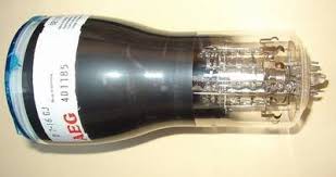
D7-16G CRT
The CRT uses an 11 pin connector, type 30-232 which is not readily available. After a little thought, it appeared that a custom-connector could be fabricated by laser-cutting some acrylic sheet, and reusing suitable valve pin-sockets.
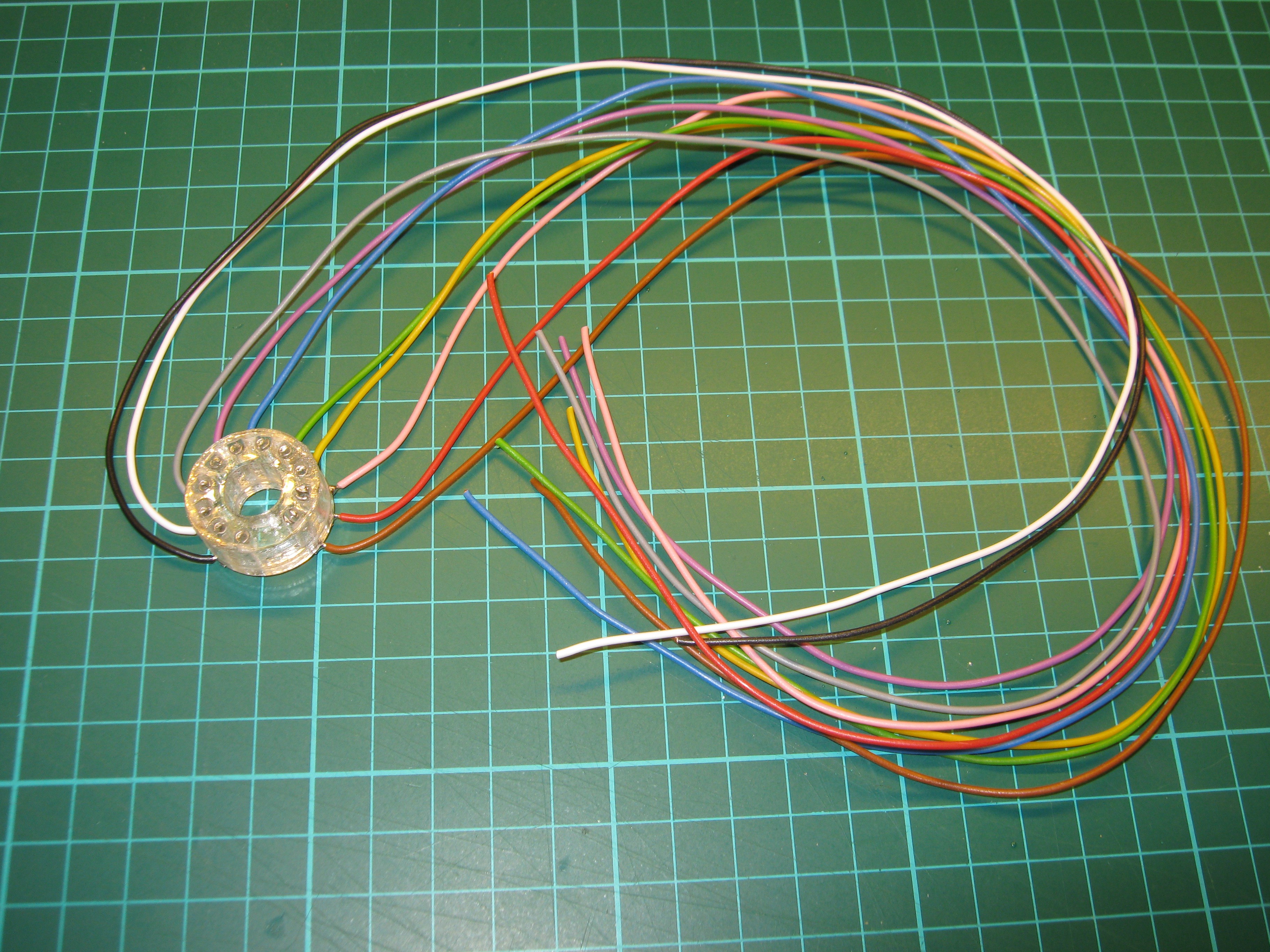
Custom 30-232 CRT connector
Designed using Autosketch, these patterns were created so that the CRT pins were centrally located inside the ‘D’s of the left hand item. Each of these patterns were then cut from 3mm acrylic sheet and glued together. Pin-sockets were removed from a new B9A valve socket, inserted into this new assembly, and bent slightly so that they did not fall out. Flying leads were then soldered and held with heat-shrink sleeving onto each to each pin.
HV PSU
The PSU section is based around an SG3525 switching regulator driving a push-pull pair of N-FETs, and in turn, a small ferrite transformer. The transformer has two secondaries, high and low voltage. The high voltage side passed through a positive half-wave rectifier to generate around 240VDC before being shunt regulated to 210V. This rail delivers around 7mA to the deflection amplifiers. The HV secondary is also voltage doubled to generate around –600V at a milliamp or so to bias the CRT and electron gun. The positive and negative rectifiers are used as an attempt to balance any DC current in the secondary, which may saturate (or at least magnetically bias) the core.
The transformer stack-up starts with primary at the centre....
Read more » Mark Atherton



 jaromir.sukuba
 Alex Muir
 Jean-François Duval
 c.Invent
Oh, I love this, but there again, I'm a sucker for both retro electronics and CRTs.
There is a direction I'd love to see this developed in - an ASCII serial-input oscilloscope display (I'm a sucker for serial terminals, too!).
Now, I think I have a display out of an old Sinclair pocket TV somewhere ....
Oh, and 1000V is considered High Voltage, not EHT in electrical terms according to the IET (even if we do still call it HT ;) )
[quote]:
British Standard BS 7671:2008 defines high voltage as any voltage difference between conductors that is higher than 1000 VAC or 1500 V ripple-free DC, or any voltage difference between a conductor and Earth that is higher than 600 VAC or 900 V ripple-free DC.