LED Coupled Logic (LCL)
Reaching sub 1 ns propogation delay with LEDs and bipolar transistors.
Reaching sub 1 ns propogation delay with LEDs and bipolar transistors.
To make the experience fit your profile, pick a username and tell us what interests you.
We found and based on your interests.
Found in the Motorola High Speed Switching Transistor Handbook from 1963. Looks like LCL was pre-anticipated by implementations with germanium transistors and diodes.
The book is extremely interesting - the best book on discrete bipolar logic I have seen so far. It goes way down into theory and device physics:
https://archive.org/details/High-speedSwitchingHandbook
I used 9 inverters from two RINGO5 boards to build a single ring oscillator with 9 stages. Due to the lower oscillating frequency, the individual inverters are able to reach a more steady state during switching.
| Vdd [V] | Idd [mA] | Vavg [V] | Vmin [V] | Vmax [V] | Swing [V] | Freq [MHz] | tpd [ns] |
| 4.5 | 80 | 3.36 | 2.86 | 3.83 | 0.97 | 70.7 | 0.78 |
| 5 | 92 | 3.81 | 3.01 | 4.54 | 1.53 | 58.6 | 0.94 |
The tpd and logic levels are very similar for the RINGO5 and RINGO9 confirming sub 1ns tpd for the LCL inverter.
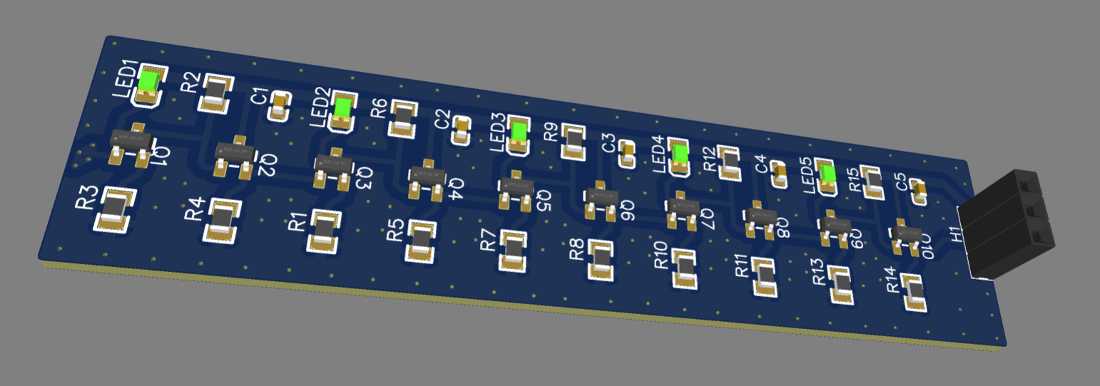
The assembled PCBs arrived after just 11 days. This is a short summary of the circuit characterization.
The full circuit of the five stage ring oscillator is shown above. I used MMTBH10 HF-Transistors in the actual built instead of the MMBT3904 that are shown in the circuit diagram. Since the source follow provides a low impedance output, I did not add an additional output driver and attached the scope directly to the output of the rightmost inverter.
The two trace above show the ring oscillator at VDD=2.7V, the minimum voltage where it oscillates and at 5V.
| Vdd [V] | Idd [mA] | Vavg [V] | Vmin [V] | Vmax [V] | Swing [V] | Freq [MHz] | tpd [ns] |
| 2.7 | 18 | 1.81 | 1.68 | 1.95 | 0.27 | 222 | 0.45 |
| 3 | 22 | 2.08 | 1.92 | 2.25 | 0.33 | 213 | 0.46 |
| 3.5 | 28 | 2.57 | 2.41 | 2.72 | 0.31 | 176 | 0.56 |
| 4 | 35 | 2.96 | 2.65 | 3.25 | 0.6 | 144 | 0.69 |
| 4.5 | 42 | 3.38 | 2.9 | 3.85 | 0.95 | 115 | 0.86 |
| 5 | 47 | 3.82 | 3.08 | 4.54 | 1.46 | 100 | 1 |
Detailed measuremt results are shown in the table above. A minimum of 2.7V is needed for the oscillator to start oscillating. This seems to be governed by the forward voltage of the (red) LEDs. At this supply voltage there is very little voltage swing at the summing node of the differential pair, meaning that the inverter essentially works as a common emitter amplifier. At 450 ps, the extracted tdp is quite low, but it's arguable wether we are seeing digital switching. The output looks like a clean sine. One issue may be that the impedance of the scope probe is too low at the harmonics and is remove any edges. I need to look into an impedance matched set up.
Going to higher frequencies we see an increase in output voltage swing, but a reduction of frequency. At 5V the tpd is still at a respectable 1000 ps.
I'll try to keep it brief. You have seen me investigate several different styles of discrete logic, including the weird DTL derivative LTL.
One obvious omission was emitter coupled logic, ECL.
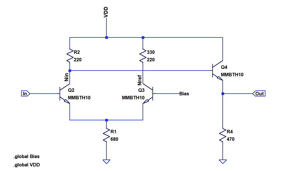
Let's ponder about the right side of the differential pair (Q3). It does not only consist of a resistor and transistor, we need a static bias reference in addition. This adds a lot of components to what could be a simple RTL or NMOS inverter.
But who says we have to form a differential pair from two identical transistors? The circuit above shows an inverter formed from an assymmetric differential pair consisting of a LED and a bipolar transitor. The benefit of this is that it saves one transitor, one resistor and the bias reference.

Create an account to leave a comment. Already have an account? Log In.
Yes, I probed that node. At low VDD it will remain constant, so that the inverter actually only acts as a common emitter amplifier. This is where you see the low swing very fast switching. At higher VDD the differntial node also changes (LED capacitance has to be charged), leading to high logic level swing at the cost of speed.
There is of course the issue of voltage variation introduced by the VF variation of the LEDs. This would be reduced with a proper voltage reference like in ECL.
The inverter works with both green and red LEDs. For green LEDs I need to raise VDD to ~6V, red are default.
You made me think of another idea !
Instead of having the diode in parallel with the input transistor, why not having it in parallel with the "common" low-side resistor ?
This could stabilise the logic levels precisely, independently from the resistor values, adding a pretty strong non linear behaviour at very low cost.
I'll have to simulate that...
Edit :
It was a stupid idea that doesn't work :-D
Edit 2 :
Daaamnit it works MUCH better when you wire the diode in the right direction !!! I should publish somewhere :-D
Click https://tinyurl.com/y4kwm7v4 for a preview :-)
>Instead of having the diode in parallel with the input transistor,
This is basically fixing the emitter potential, turning the inverter into a common emitter amplifier, or an RTL gate. Of course it will still amplify :)
At lower voltages the LCL gate is actually operating in the same mode. It's in the dark grey area between actual logic and an analog circuit...
But who says this cannot be used for logic in some way?
The benefit of the tail-resistor in the ECL/LCL gate is that it will move the emitter potential up if there is too much collector current. This can prevent saturation, if biased correctly. If you short the emitter resistor with the diode, you will drive the transistors into saturation the same way it happens with RTL.
What if you reduced the resistor's values ? The high side seems ok but 100 ohms on the low side would probably increase the speed/power ratio, I suppose ?
Since this is non-saturating logic, changing the resistor values is a bit tricky. The ratio of R1 to R2 basically defines the logic levels in connection with the supply and forward voltages of the semiconductors. The biggest lever on speed is actually to change the logic levels to minimize swing. But of course that comes with noise margin issues.
I see, because a limiting factor is the RC constant of the output for example...
I should try this with my AF240s (Ge) and those ultrafast BFS480 :-P
one day.
Note : this trick only works if you only desire the NOR gate. ECL is great because the complementary output is also provided, it greatly helps to have both outputs for logic minimisation and saves another inverting layer.
Well you could mix the gates with true ECL gates if you need a complementary signal.
yes, the saving is significant. But then you need to tune your ref with the diode drop, and/or vice versa
what an interesting challenge ;-)
I suspect 2 things :
* The LED can be replaced by a couple of Si diodes for example
* The capacitance of the PN junction is a bonus and not a drawback
The differential junction has to move relative to VDD, so the capacitance should play some role. I made some trials attaching parasitic caps to various nodes and was quite surprised that there was little effect. The output impedance of the gates is really low, due to the emitter follower. This helps quite a bit.
A true ECL gate is still a bit faster, but that is also because the additional gm of the reference side helps a bit.
Yeah, Si diodes should also work in place of the LEDs.
Looking forward to this project. For sure I expect LCL to be faster than my Light Logic :-)
It is for sure. Maybe LED-coupling is a bit of a misnomer here. I am not sure whether the "E" in ECL refers to the emitter follower or the differential pair :)
Become a member to follow this project and never miss any updates
 Tim
Tim
 Ted Yapo
Thinking out loud :
The diode's drop is about 3 to 4 times the Vbe. What if it was 2×Vbe ? There would be less saturation in the output transistor's ... Oh but it is not saturated because it's a common emitter and having only 1× Vbe of output swing wouldn't help, I guess... so Vdrop should be around 2V or 3×Vbe, or 3× silicon diodes.
I suppose an old red LED would be great.
Did you measure your diodes' drop ? or even probed that node ?