David Tucker
-
What a drag
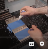
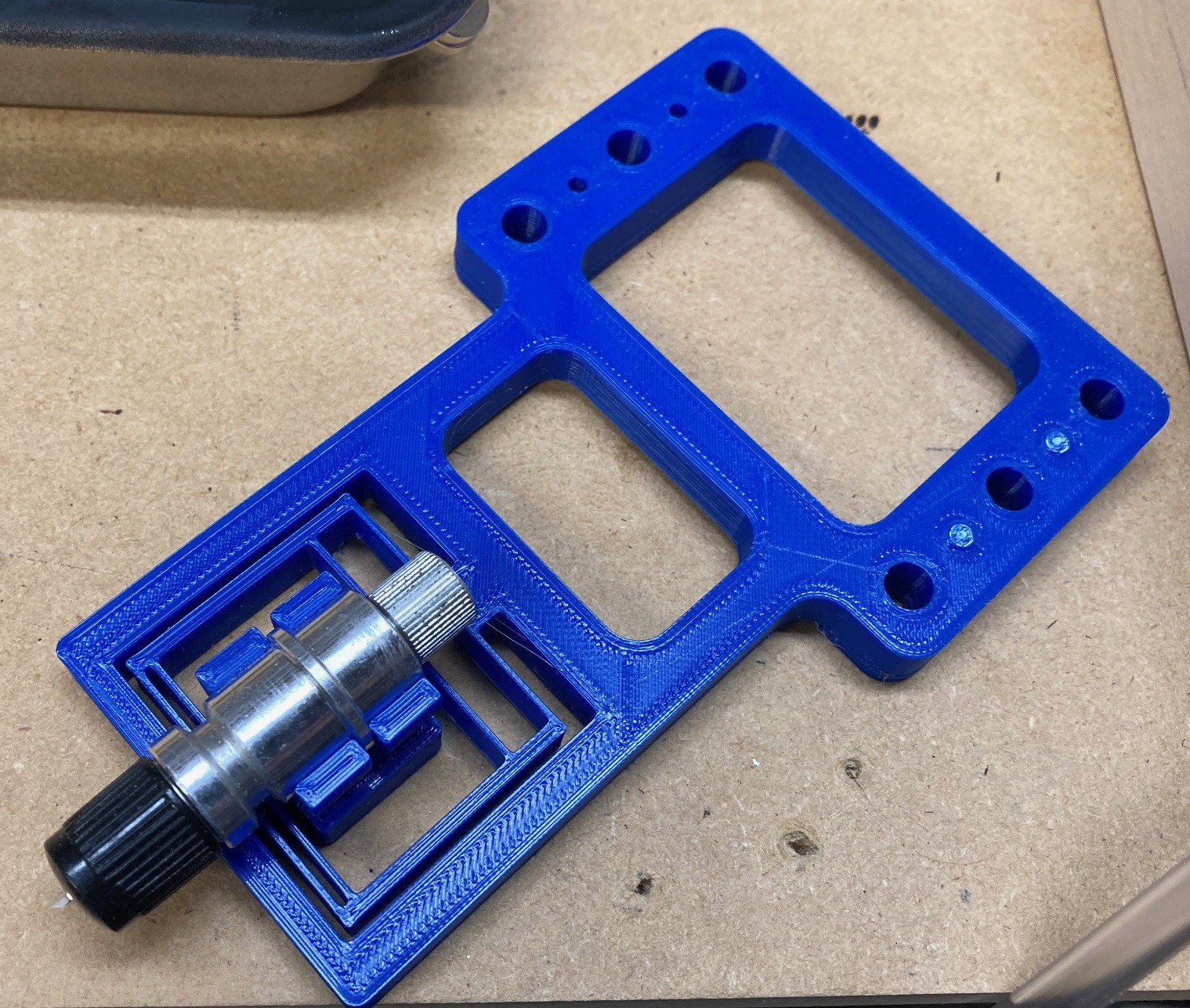
06/16/2021 at 05:08 • 0 commentsI finally got around to testing my drag knife out. This particular unit uses a very small blade that can be extended down past the end of the holder. You adjust the blade up and down to match the thickness of the paper you are cutting, ideally so you just barely make it through the material.
![]()
The blade has a small offset to it so it trails behind the movement of the holder. That helps the blade self orient in the direction of motion. However when you change directions the blade will lag behind and follow a distorted path. If the change in direction is large enough then the blade can bind up and cause a small tear in the material.
To compensate I'm using a software tool that distorts the path of the housing to correct the path of the blade. For this small of a blade this correction is not critical, but it does seem to help compared to an uncorrected cut.
![]()
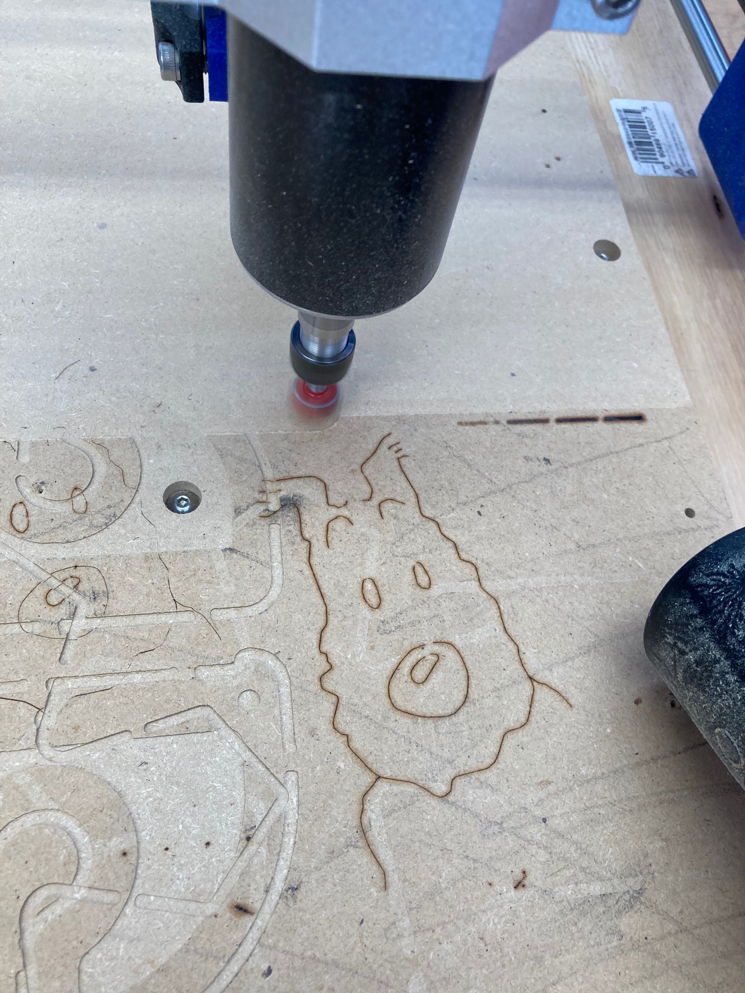
The end results were not very good, all the corners are soft, no matter how much compensation I used. And things were very inconsistent. Watching this for a while I saw two issues. First my original tool holder was weak and flexed easily and it did not hold the tool very well. And second I have a hard time getting a consistent height above the material.
![]()
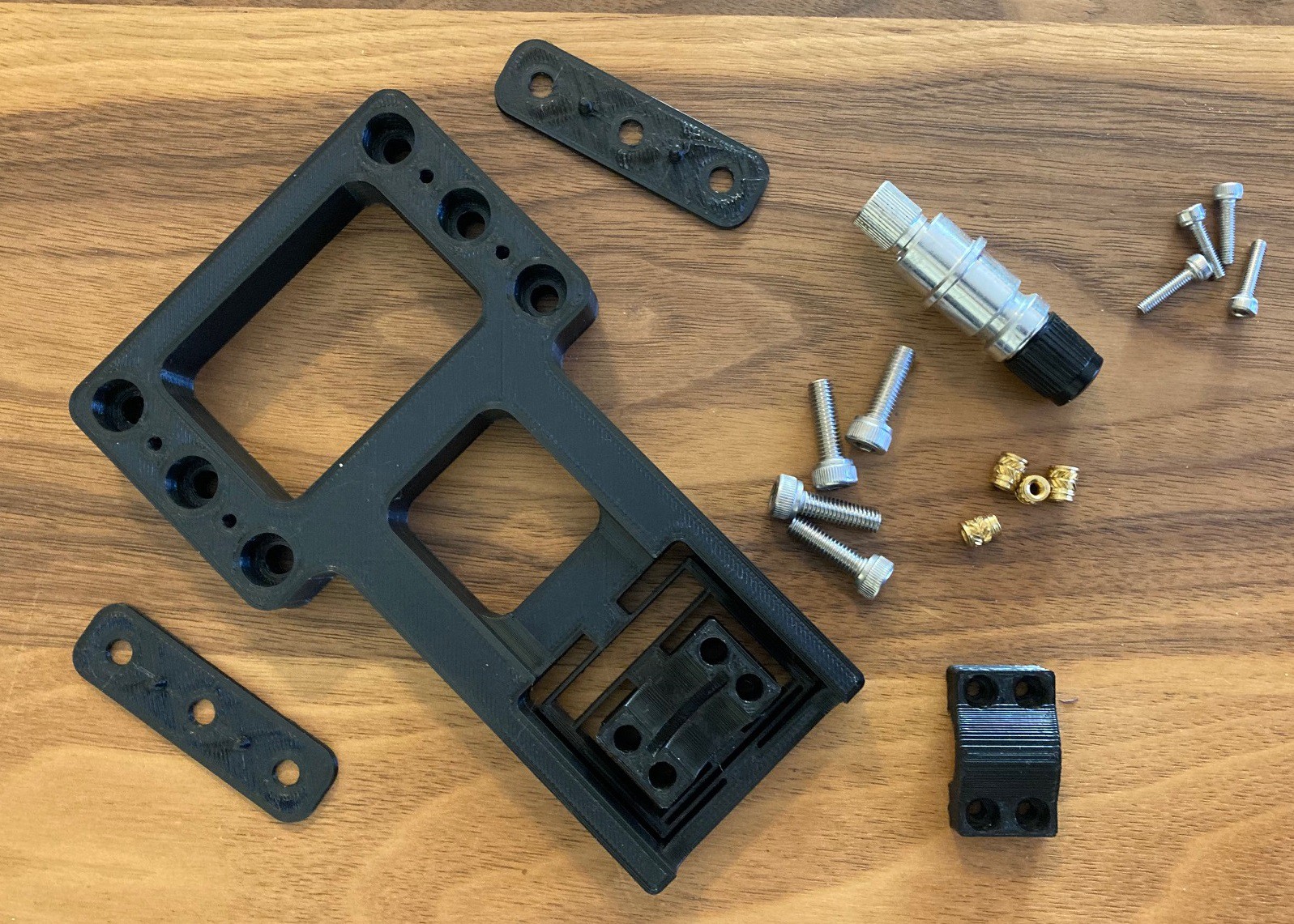
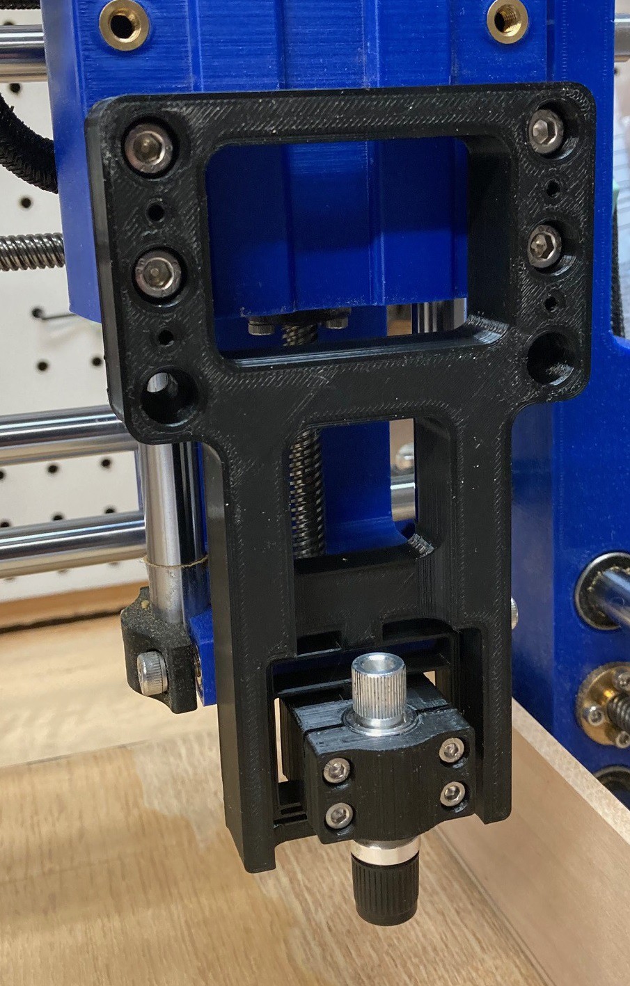
I have not solved the height problem, I need to experiment more with that. But I did print up a new tool holder that is much stronger and that firmly clamps the tool. It still wiggles a bit but it feels much more solid. I need to test it out to see how much it helps but I have a feeling it will work well. Part of my struggle is because there is such a large distance between my Z carriage and the work surface. I need to extend everything out really far to make it all fit. If this is not strong enough I may look into raising the surface of the bed up 6" or so.
Hopefully tomorrow I can find the time to test this out and then we will know for sure.
![]()
-
Heat!
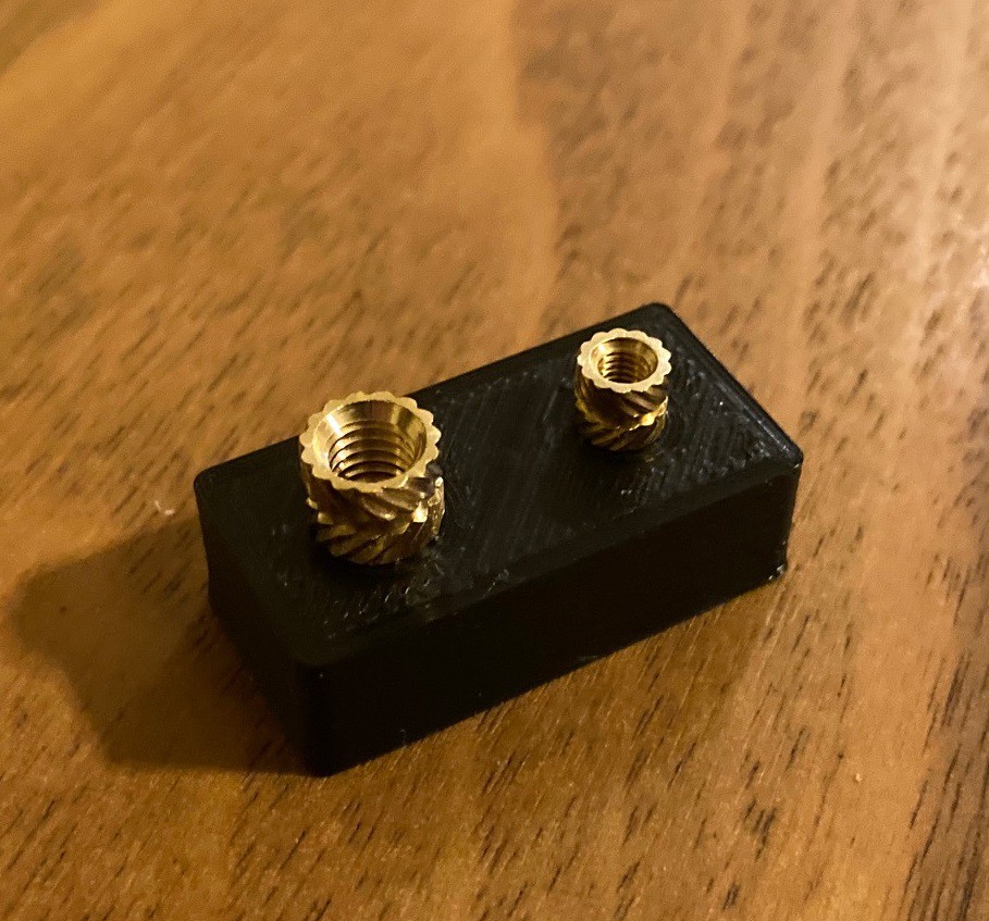
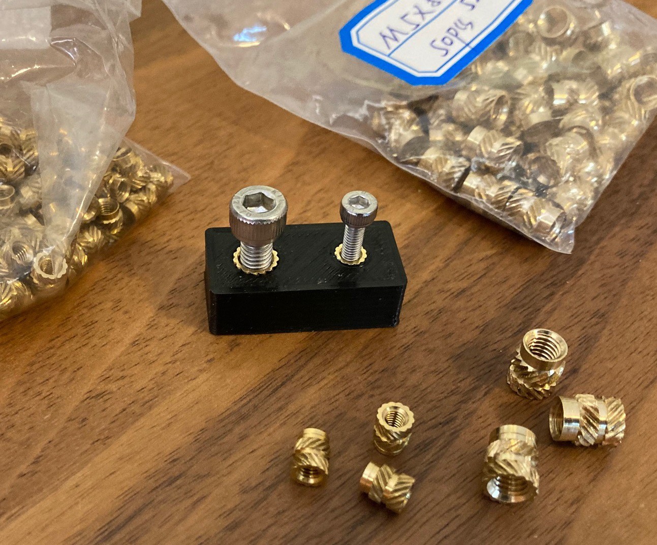
06/16/2021 at 04:55 • 0 commentsI ordered new heat set inserts that match the ones on my parts list from Ali Express a while ago and they showed up yesterday. After measuring them I was able to resize the holes for them to make a better fit. I went ahead and updated all my models on my thingiverse page to match the new size. This should make things fit better.
![]()
![]()
-
Hold Up
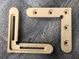
06/08/2021 at 04:52 • 0 commentsI'm trying to work out the best way to finish my spoiler board with some sort of hold down clamp. There seem to be a never ending number of ideas out there, but I think they all fall into three basic styles.
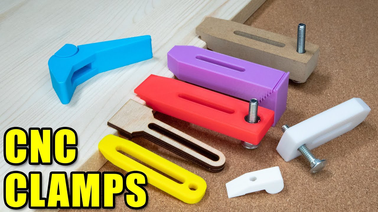
- Top clamp - Screws and clamps that press down on the top of the material, pressing it into the spoiler board. These are probably the most secure, they will hold the material even if the bit pulls up on the material. However since they stick above the work piece and cover part of the top you loose some material, and run the risk of the cutter and clamp coming into contact.
![]()
![]()
![]()
![]()
![]()
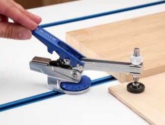
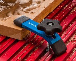
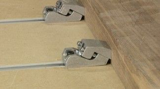
- Side clamp - These press against the side of the work piece like a vice. Typically these are fastened into the spoiler board and can be quickly removed and installed. They are not as strong as the top clamps and an up cut bit can cause the part to lift. However they are very convenient and popular and since they only engage at the sides you can use more material and potentially there is less chance of the cutter contacting the clamp.
![]()
![]()
![]()
![]()
![]()
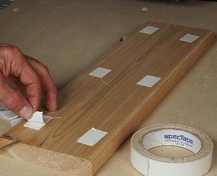
- Bottom fixture - Using glue or tape of some sort to directly attach the material to the waste board. Typically this would be either double sided tape, or two pieces of painters tape that have been attached with some CA glue (krazy glue). The advantage of the painters tape is you can use a roller to press each piece of tape onto the material before affixing them to each other with the glue. In theory this holds things down better than just using double sided tape. The up side here is there is nothing to run into so you don't need to be careful when planning your paths, and the center of the part is glued down so you don't need tabs to hold parts that were cut out to the perimeter of the material. On the down side this is the weakest clamp, if you are not careful it can come apart. Also if the cutter goes through the tape it will gum up the cutter.
![]()
![]()
There are also many different ways to affix the clamps to the table.
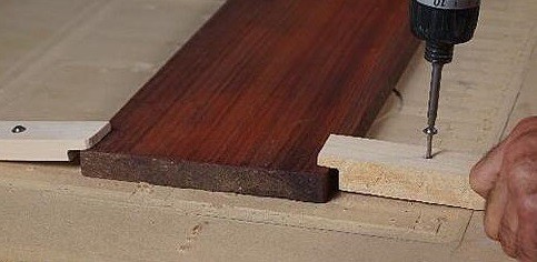
- Screws - The simplest is to just screw the clamp (or part) directly into the spoiler board. This is easy and very strong, but it wears out the spoiler board over time.
- T-Nut - By drilling a hole through the spoiler board you can affix a 3 prong t-nut to the bottom of the board and then use a bolt to affix your clamps. The T-Nut must be inserted partially into the board so it limits how deep into the spoiler board you can cut safely, but if things go well this is relatively safe.
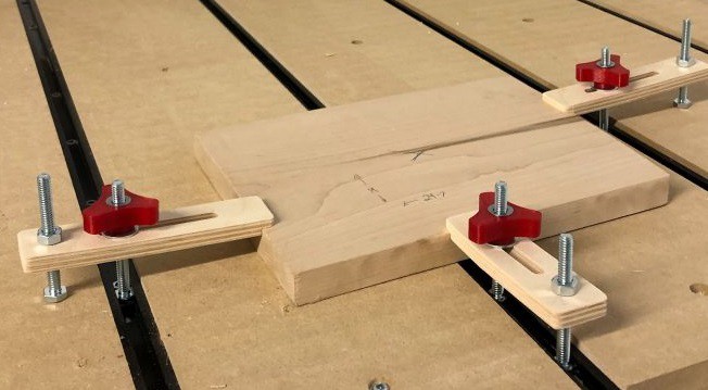
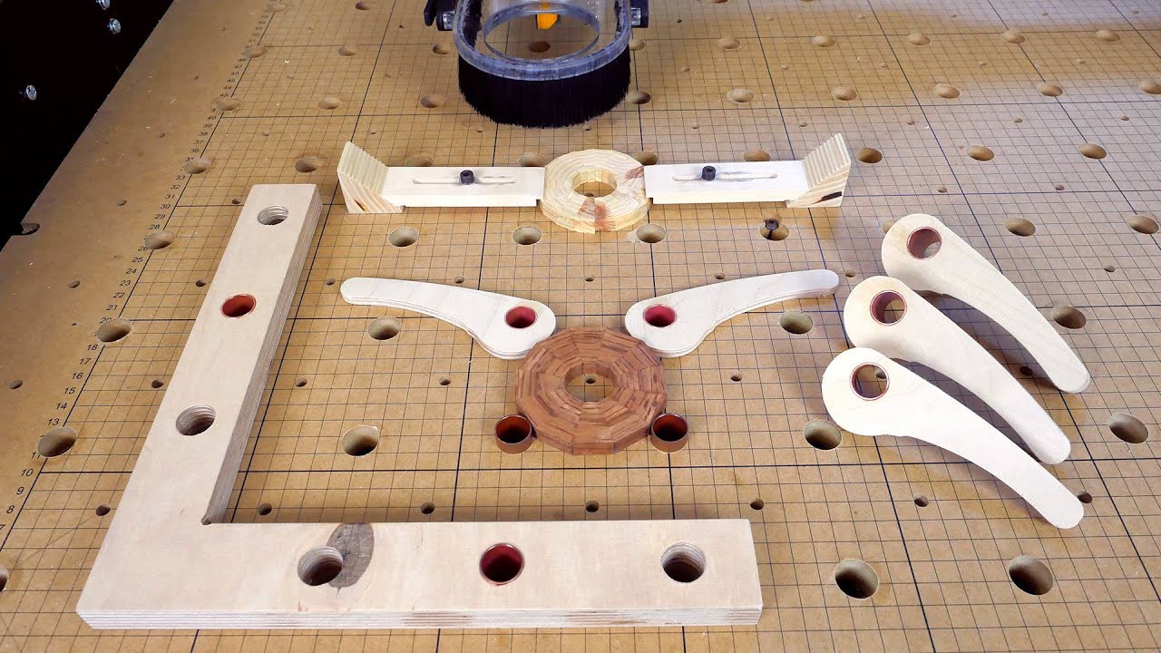
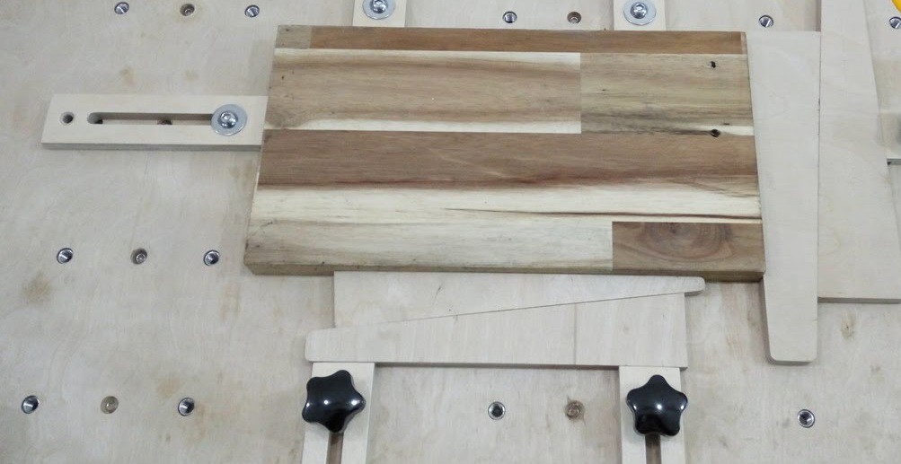
- Cam & Hole - You can drill holes through the spoiler board and then use some sort of a peg and cam setup to apply side force to the piece. This allows you to use the full spoiler board surface safely and it requires no extra mounting hardware. It is limited to side clamping only.
- T-Track - Using aluminum T-Tracks you can then use an inverted bolt to clamp parts to the track. This provides great adjustability in one direction but the nut tends to stick up fairly high above your work piece. Also the track must be securely mounted to the base or it can pull out. Some users cut T-Tracks directly into the spoiler board but this is a fairly weak solution.
Anyway that about sums it all up. I need to think of one or two of these to use on my setup...
- Top clamp - Screws and clamps that press down on the top of the material, pressing it into the spoiler board. These are probably the most secure, they will hold the material even if the bit pulls up on the material. However since they stick above the work piece and cover part of the top you loose some material, and run the risk of the cutter and clamp coming into contact.
-
Too darn hot
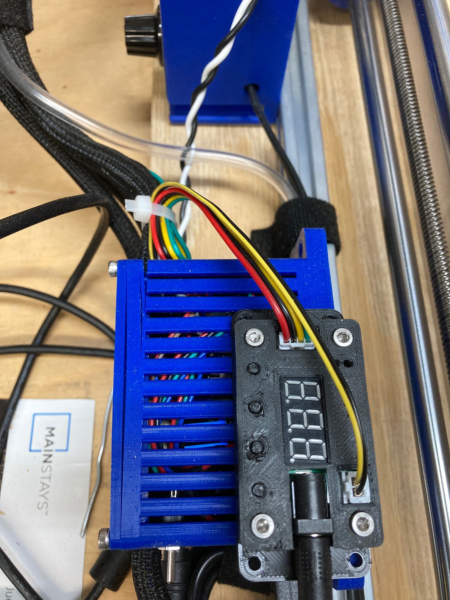
06/07/2021 at 04:00 • 0 commentsThe temperature outside is over 100 degrees Fahrenheit (38 C) here in Tucson, Arizona and so now I get to see how well my machine holds up in extreme heat. I measured the garage at 98 F (37 C) today around 2 pm, that should be the peak temp for the day. It was hot enough that my stepper motor drivers were a bit unstable, when powering up the machine they tended to get stuck in a runaway oscillation between two poles. However once I got that settled down the machine ran just fine.
More interestingly the plastic parts on the machine seem to be holding up well. I printed everything out of PLA rather than using a higher temp filament like PETG or ABS so I'm a bit worried about it all warping in the extreme summer heat. However I can't see any evidence of warping or cracking and nothing is loosening up even.
![]()
I do have some separation on my electronics housing, however this was made too small and I have a lot of thick cables crammed into the housing with only the force of the lid keeping it all in place. Coming up with a better way to manage the electronics is on my list, but not high enough yet. At some point in time I would like to have a 5th stepper motor, maybe then I will come up with a better way to house the electronics.
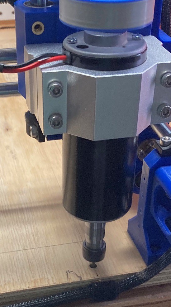
The spindle on the other hand got up to 135 F (57 C) when running. It held that temp consistently over the hour I ran it but still it is quite warm. That may not lead to a long lasting motor, time will tell.
-
Spoiled!
06/07/2021 at 03:30 • 0 commentsI finally got my new spoiler board all put together. I homed the machine then manually jogged it around looking for interference and worked up the min and max extent of travel in all directions. Then in Fusion 360 I modeled up a block that was as thick as the base board and had the dimensions of my travel. From there I planned out where to route my hold down bolts.
When doing the cam side I wanted everything to be based on the home switches, so I added in a dummy block that offset my waste board from the machine origin, that way I could set the cam origin at the home position. I'm sure there is a better way to handle this, but nothing jumped out at me in Fusion and this seems to have gotten the job done.
![]()
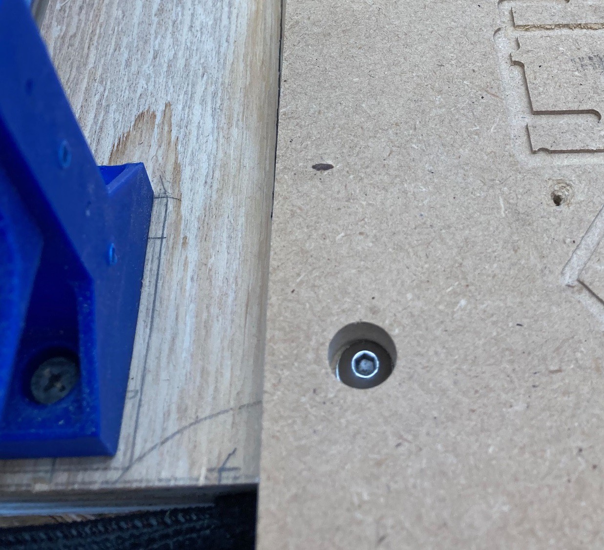
Anyway once I had everything modeled up properly I let the router drill holes in the base for some m5 3 prong t-nuts. Once the holes were drilled I flipped the machine over and pounded them in place. Then using double sided tape I placed my spoiler board on top and ran the program again to drill holes (and pockets) in the waste board. Finally I took it all apart, removed the tape then used 25 mm long m5 button head socket bolts with a washer to clamp the spoiler board firmly to the base. The waste board was 14 mm thick and I used an 8 mm deep pocket to recess the bolt heads, the heads worked out to about 4 mm thick so that should give me plenty of clearance for any accidents.
![]()
For surfacing I have an 18 mm router bit that did a good job. I used a 6 mm stepover and used the surfacing tool in Fusion to run a zigzag back and forth in the x direction. My Y axis is a bit out of tram and this way the error is hidden and with the extra step over any mistakes in my X tram would be covered up as well. Anyway I could not feel any variation in the finished surface so I don't know that I needed to be so cautious.
![]()
The surfacing tool path has an annoying habit of doing a ramp in and out past the extend of the target object, as well as doing some half circles at the end of each pass off the waste board as well. That would be fine but I sized my board to be exactly the dimensions of my routers safe travel range. To cover this up I added an inset to the tool path so that all the extra travel was inside the boundaries of the waste board. This seems to have worked well, at least I was able to complete the job. I could have used a pocket to smooth the surface out with but that uses a spiral pattern and I wanted a perfectly smooth board. I was worried this would amplify any errors on my tramming. Anyway the end result was good so no need to fuss with it.
![]()
I removed about 0.5 mm from the surface of my board. You can program this into the cut in Fusion, or more simply just zero the bit out on the surface of your waste board then manually change the z offset to be 0.5 mm higher than its current position to set the zero point 0.5 mm into the surface. This worked out well in universal gcode sender. In the end I was way to cautious on my feeds and speeds, I could have run this several times faster than I did. I ended up using the override tab in UGS to bump the feed rate up by 200% so the cut did not take forever. Even then it was still an hour long job. Next time I will practice on some waste material and dial in the cut rate first.
I could have taken some more material off to get a perfect finish, but I figured this was all just a practice. The goal was to get a repeatable process that I could use to make a fresh waste board at any time. Or more interestingly I can now use this to make any sort of an insert onto my machine, so I could swap out a laser table, or a 4th axis lathe or just a custom jig for a specialty project. As long as I don't mess with the limit switches I can repeatable cut my hold down holes in any material. That is one of my favorite parts of the CNC, it can be annoying to program but once you have it dialed in the accuracy is beyond amazing compared to what I can achieve with my simple shop tools.
I still need to add the side skirts back on and get my dust boot back in place but overall I'm really happy with this and it was a very low cost way to make the machine more versatile and more accurate.
-
Squaring and Tramming
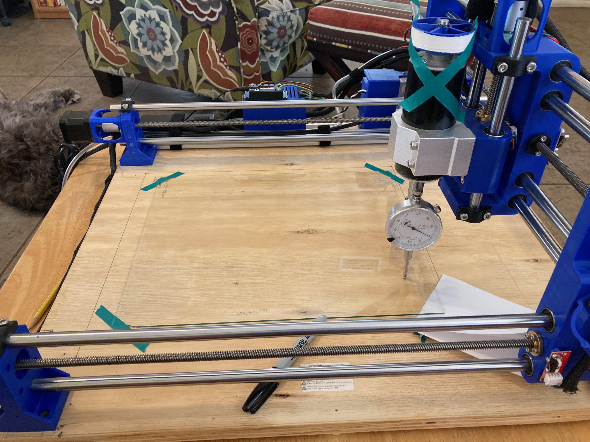
06/01/2021 at 06:01 • 0 commentsI decided to square up and tram my system in preparation to making a replaceable waste board that is easy to swap out and that has been surfaced.
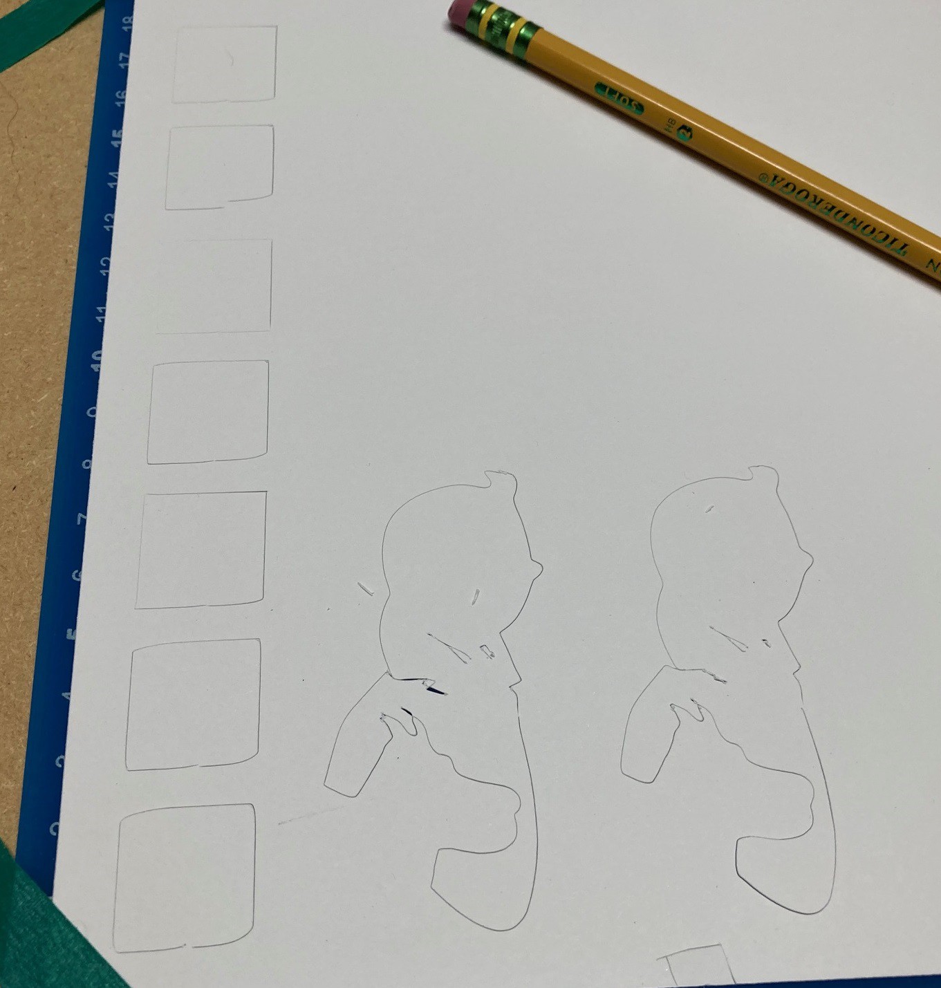
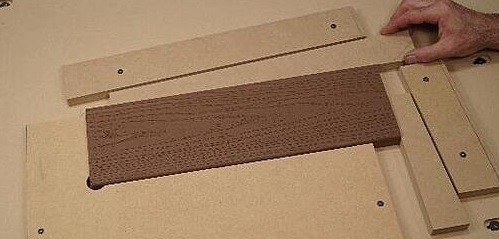
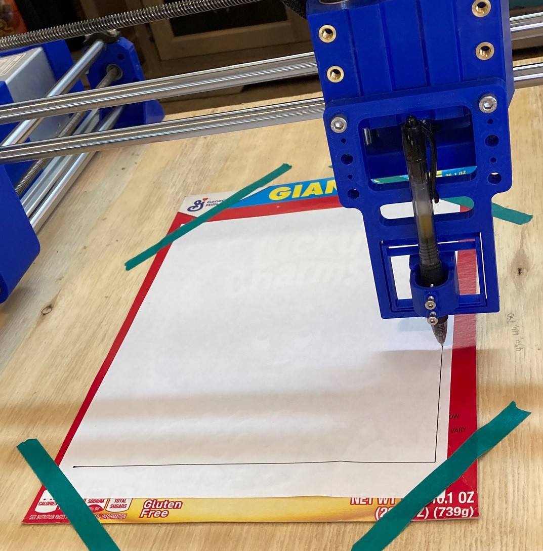
The first step is simple enough. To square the Y axis to the X axis we just cut a pair of squares out of some material, then flip one over along the X axis and check if the Y axis diverges from each other. Or if you don't want to waste any materials you can just draw a square on two pieces of paper, then flip one over and hold them up to the light to see if the squares line up. If there is any divergence then dial the Y end stops in/out as needed and repeat the measurements.
![]()
The next step is more tricky. To tram up the spindle we need to first work up a parallels surface to square against. An easy way to do this is to place a sheet of glass on top of the bed, then using a dial indicator we can run it back and forth over the glass to find the low spots then shim them up till we have as flat a surface as we can manage.
![]()
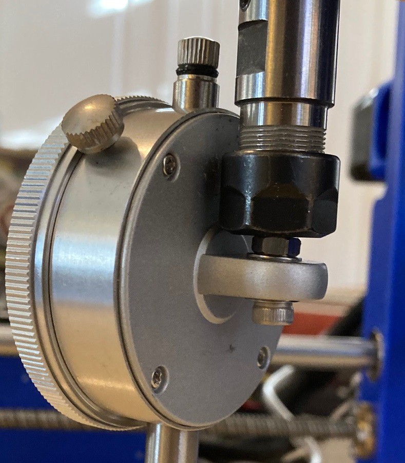
To secure the dial indicator to the spindle I took the back off and rotated it 90 degrees then fixed a bolt through the hole on the back and then chucked the bolt into the spindle collet. I also taped the spindle up so it could not rotate, that helps keep the measurements more consistent as you move the spindle over the glass.
![]()
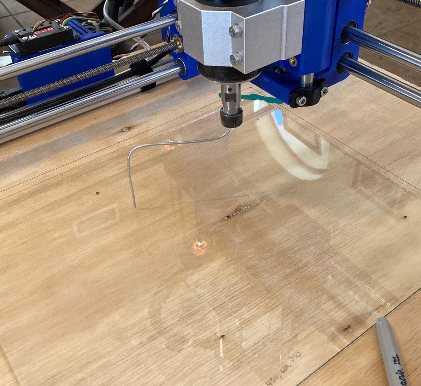
Once the glass is level then I chucked a piece of bent wire into the spindle, jogged the spindle to the center of my glass, then lowered it to the point where the wire was just about to touch the glass at the highest point. Then by spinning the wire around I could see how much out of true the spindle is in both the X and Y axis. To true things up in the Y axis (called nod, as in nodding your head yes) I placed a small piece of aluminum tape on the top or bottom of the spindle holder as needed to pitch the spindle forward or back. Repeat the process as needed till you have it square.
For the Y axis things are trickier. I have made the machine very symmetrical so it should be fairly true, however to correct for tilt (as in tilting your head side to side) it is easiest to loosen the spindle a bit, then twist the motor and mount in the direction you need before tightening it all back up again. It is not perfect but it can bring thins closer to true.
I measured about 1 mm of tilt in the Y axis using a 100 mm long wire (200 mm in total from side to side), Using a 20 mm blade to level my spoiler board with 30% stepover then should give me less than 0.05 mm of error along the Y axis. Hopefully that is close to invisible.
![]()
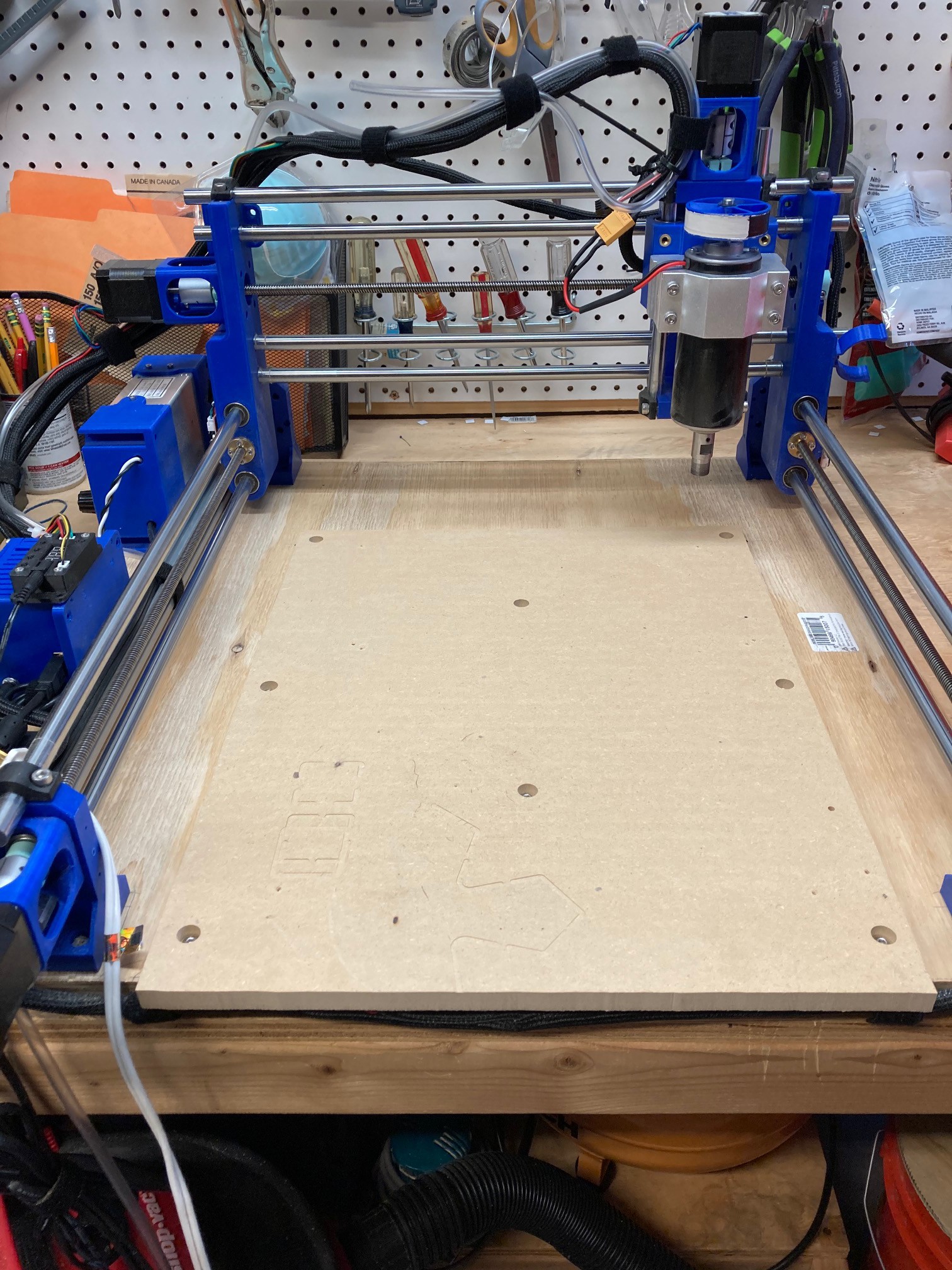
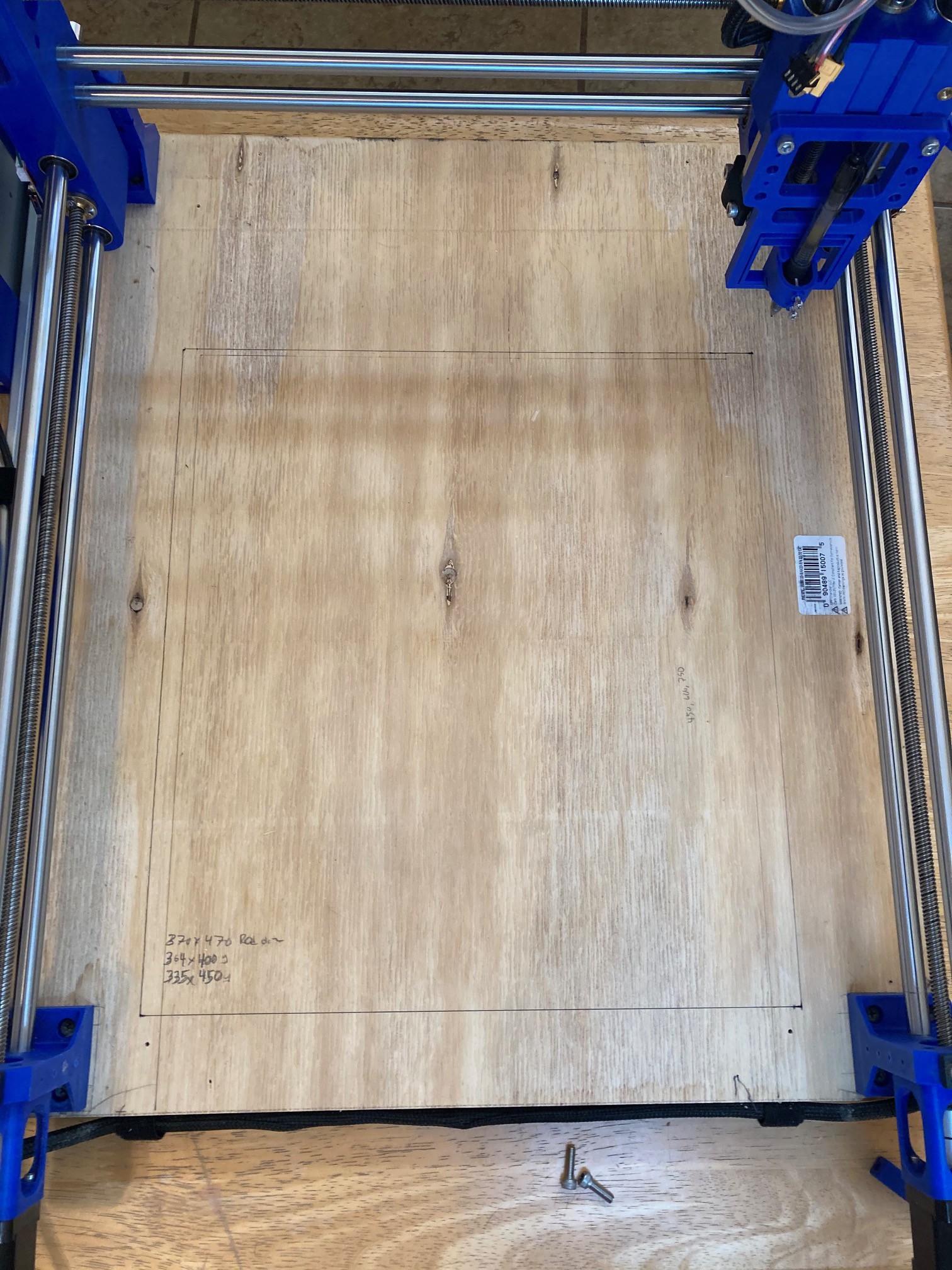
Now I need to plan out how big to make my spoiler board and how to mount it. For starters I loaded up my pen and jogged the machine to the extent of motion. This is not perfect because different attachments protrude different amounts in the X and Y directions, but it helps me get a rough idea of where to place the board. Tomorrow I will try to finalize the plans and come up with a way to get my machine to route holes in everything.
It is a bit hard to see the lines but if you look closely you can see that there is a good amount of space at the rear of the machine that is wasted. Fortunately it is not lost, it just shifts forward. But the bit does extend a ways past the front of the base of the machine when jogged all the way forward. Someday I will need to rethink things and add in a raked Y gantry holder to bring the spindle further back. This may help stiffen up the machine a bit as well since the weight will be more evenly distributed.
![]()
This guide by Roger Secura was a help in working out how this all works.
-
Notes
05/30/2021 at 22:44 • 0 commentsI have not been very active with this project for a while now. My son graduated from high school and getting him through the end of school, graduation, hosting a party and finalizing college plans has sucked up most of my free time. Things are slowing down again and I want to get back into this project. I thought the best way forward was to make a plan, so here are some thoughts on what I want to tackle next.
Test out my small drag knife. I have some plugins to try, I just need to go out and do it.- Make a large 3D printed drag knife based on a utility knife blade.
Do a shootout between drag knife and laserand work out what one is best in what situation.Square up my system, I checked for square when I built the system, but I have not really payed any attention to dialing this in perfectly.Level the spoiler board, for some reason I never did this and it is time.Create a removable spoiler board system.- Create more advanced hold downs than just wood screws into the base.
- Create a replaceable drag knife base that is very level and easy to change out.
- Create a replaceable laser base out of metal or some other non flammable material.
- Come up with a routine for making double sided carves with a high degree of registration.
Test depth of focus on laser cuts.I'm not sure that I'm using the optimal focus height.- Test milling aluminum.
- Test milling a pcb board.
Design a 4th axis rotary jig.This needs to serve many purposes so it may be tricky to design one device that can handle everything. Ideally it would meet the following goals.- Support any diameter material from 1 mm to the max height of my rig (75 mm?). I don't want to waste working height by having rollers under the object, so this points towards a 3 jaw chuck or other rotary clamp rather than using rollers.
- Swappable face, a 3 jaw chuck is probably the most versatile, but we should support a wood face that can have objects screwed directly to it, as well as a pair of cones to help hold objects with centering holes on them.
- Support any length object from 1 mm to the max of the bed. We need some sort of a low profile rail system so we can add in supports quickly and easily to the jig.
- Hold pens, rods, cylinders (cups), wood, aluminum, etc.
- Handle material that has a slope to its surface (like a tumbler). We probably need to angle the chuck relative to the table to make this work. It is best if the center of rotation is near the face of the chuck so we don't loose much depth. This could also be used to engrave the inside of rings or other objects.
- Have a reasonable level of resolution on the Rotation axis. Need to do the math to ensure we have a reasonable resolution on the surface no matter the diameter of the object.
- Handle laser and milling, this is a tall order, lasers don't need much support but milling is going to require a lot of support.
- Ideally support 4 axis movements, that is letting the Y axis move side to side while still supporting the X, Z and Rotation axis. This allows us to mill large flats onto a round object. This will probably require moving off of GRBL and onto a more powerful controller. This also puts a much stronger load on our rotary motor, it may be more of a pipe dream than a reality for a 3D printed rig.
- If we don't support a true 4th axis then we need to come up with a way to lock out the Y axis while we run the Rotation axis. I'm not sure how to do this yet, it will take some experimentation.
-
Collimation of events
05/14/2021 at 01:24 • 0 commentsI just noticed that NEJE.shop has updated there laser diode module page and there are three new modules now available. One is a cheaper 5w version of my 7.5w module model number N40620, interesting but not exiting. The exiting one is the new A40630 module. This is the same 7.5w module I have but it adds a collimating lens to the diode. NEJE calls this a FAC or fast axis correction lens, you can see an example of it on this ebay listing. This has the effect of reducing the speed (angle) at which the fast side of the diode diverges, the end result is the spot size of the laser is more or less square and smaller in area.
According to there specs they are reducing the spot size from 0.08 x 0.06 mm to 0.04 x 0.04mm, that takes us from 0.0048 mm^2 to 0.0016 mm^2, a 3x reduction in spot size! The collimators must reduce the laser power by some percent but even so we should be getting quite a bit more power out of the laser with this. And this should restore the engraving potential so one laser can be used for both engraving and cutting without compromising quality.
The newer A40640 15w module also uses this correction lens and claims the same 0.04 mm square spot size. That combined with double the power output on the laser probably puts this close to 4x more cutting power than my uncorrected module. A K40 CO2 laser uses a 40 watt laser tube, that is still several times more optical power than the 15w NEJE, but it also has several times larger of a spot size so this may be approaching the cutting power of a $300 CO2 laser. Keep in mind the CO2 laser uses a very different wavelength (infrared vs blue) and so it can cut some clear materials that the NEJE cant.
The minimum spot size has everything to do with the wavelength of the light we are using. Our blue lasers have about a 450 nm wavelength (0.00045 mm), while a CO2 laser has a 0.01 mm wavelength. If we had a square (round) spot in both cases then the blue laser should be able to focus down to a much smaller spot size. in practice the CO2 laser is probably producing a 0.3 mm square spot size, while my laser diode is producing around a 0.1 mm square spot, and the new modules above claim a 0.04 mm square spot size. Assuming this is true, then the new module has a 50x smaller cutting area than the CO2 laser! That sounds too good to be true, but I suspect a 10x improvement is well within reason. Also keep in mind this is the ideal cutting area, beam divergence can have a big impact on how thick of a material you can cut.
Anyway things are getting exiting for laser diode cutters, they are getting close to being powerful enough to compete against low end CO2 lasers, while being much simpler to operate and maintain (no large glass tube, no need for water cooling). Exiting times indeed.
-
Notes to my future self
05/13/2021 at 01:42 • 0 commentsI have been thinking it over and I think I messed up my laser depth cut tests earlier. I need to set the focus height for the optimal first line cut before attempting to test if lowering the laser has any benefit. I'm fairly certain that I was starting from a lower depth before and there may not have been any benefit to going even lower after that.
In addition I want to run a test where I move the laser sideways to cut a wider kerf before attempting to cut deeper. I suspect running two or three side by side cuts combined with two or three depths may be enough to get through much thicker pieces of wood.
Finally I need to run some tests to see what the optimal focus height is for engraving. Is it really true that engraving should be focused at the surface while cutting should be focused deeper? My tests so far don't seem to show this, but they have been far from scientific up till now. I need to come up with a way to measure the spot size (or line size) accurately so we can try to find the smallest spot with more precision than the ramp test. Maybe it is time to dig out the microscope.
-
Blade Runner
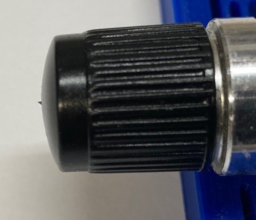
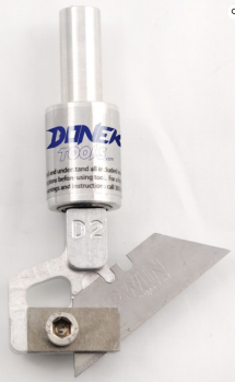
05/10/2021 at 05:43 • 0 commentsI picked up a small drag knife when I first built my machine, but I never worked out how to use it. Now that I'm messing with the laser I thought it would be good to dust it off and work out the kinks. The knife I have is similar to a Cricut cutter with a small 4mm diameter blade. I have it mounted on a 3d printed flexure to help if the tool contacts the work surface.
![]()
These small blades have an adjustment on the top that extends the blade a fixed amount. Typically you would extend it just past the depth of your material and then lower things so the blade holder is just in contact with the surface of the material.
![]()
There are larger holders that use a box cutter blade and in this case we usually lower the blade to the surface of the base material and leave excess clearance at the top of the blade. You can typically raise and lower the blade a bit in the holder to change the blade offset (the amount it trails behind the pivot) to adapt to different material.
In either case if we try to cut a right angle then the rapid change in direction of the cutter at the corner will cause a small tear in the material to be cut, and if you are really unlucky it can cause the cutter to bind up and break. We can work around this by either rounding all corners in our cut file or we can add a program step where the cutter is raised up so it just drags on the surface of the material then perform a circular motion with the tool to reorient itself properly.
GrblGuru has a nice video that illustrates how all of this works. There tool should be able to take any outline and adapt it for use with a drag knife. It is something I need to look more into.
![]()
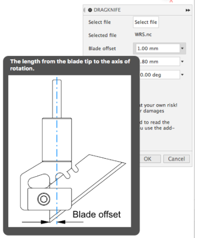
I wanted to use Fusion 360 for my CAM work, and I came across this nice looking drag knife plugin by Peter Böker. Not only does it take care of the corners it comes with some great documentation on how to make it all work well. It does cost around $10 but if it gets the job done then it is a small price to pay.
Anyway I need to spend some time actually cutting things out to make sure this all works. But at least we have a start on trying to work out the details.
MultiBot CNC v2
A low cost 3D printed CNC that can be built with minimal tools yet is capable of great things.