David Tucker
-
Sealed it!
04/15/2021 at 01:11 • 0 commentsI have been struggling with air leak around my over the lens nozzle. I have been thinking for a while of ways to seal this up. I could put a piece of glass in the top of the setup, but that would cut down on the optical power of the laser and it could heat up. I could add an O-ring to the nozzle so that it seals around the lens when installed. However the lens has a knurled edge to it and I don't think the O-ring would be able to seal properly.
![]()
I decided to just put a small bead of silicon around the edge of the nozzle where the lens mates at the top. I let it dry overnight then tried to remove it just to check how it turned out and I could not get it to budge at all. I have a feeling this will be tricky to get off safely. However it appears to work quite well. There is a small amount of air leaking around the lens but 95% of the air is being directed down through the nozzle now.
This is probably a dumb idea, or at least you should seriously consider what you are doing before you start. I already set the focus properly to 5 mm below the bottom of the laser housing, and I am unlikely to be changing that focus any time soon. Also if you use too much silicon it could ooze out in front of the lens and cause a fire hazard or at least partially obstruct the laser. And of course being semi permanent this makes it really hard to maintain the laser. Time will tell just how good of an idea this was, hopefully it is not a permanent install.
---
![]()
Edit, turns out this was in fact a bad idea! Even though I thought I used a bare minimum of sealer it ended up oozing into the lens housing and made a real mess. With a bit of care and a lot of patience I was able to clean it up and get the laser back in business. On the up side it did seem to make a perfect gasket and the air is still mostly contained.
It is hard to tell from these pictures but that is a solid plug of silicon embedded in the top of the lens housing and in the top of the nozzle as well. It was about 4 mm deep into the hole. Fortunately the lenses is way on the other side and it never came close to getting touched.
-
Regulation
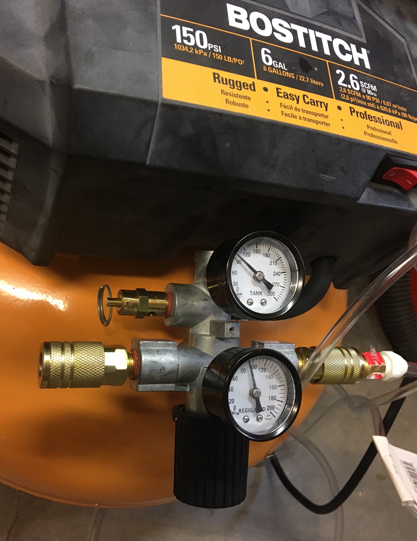
04/15/2021 at 00:39 • 0 commentsSo the pressure regulator on my Bostitch compressor has never worked well. It tends to jump all over the place both when adjusting the pressure and when starting and stopping the flow of air. I would try to dial it in to 30 psi, but when I turned on the air the regulator would completely close up and stop all air flow. So I would dial it back up to 30 psi with the air running and when I then shut the air off the regulator would jump to 50 psi. Even worse turning the air back on may give me 40 psi or 20, it was all over the place.
![]()
So I took my regulator apart to have a look at it. It is a massive all in one unit with both gauges, pressure relief valve, and the inlet and outlets all connected into one monolithic cast piece. There is no way to replace just the regulator. On top of that you can only strip it down so far, the poppet valve and spring are press fit into the housing and it is made of plastic so I was unwilling to try and wrestle it apart.
This is a piston style regulator, rather than a diaphragm style. That means as the air pressure changes on the outlet side we have to mechanically move a piston back and forth in order for the pressure to regulate. The piston looked ok but it was a bit dry so I wiped everything down and re-greased it all and put it back together. That seemed to help a bit, now the regulator reacts much quicker when I turn the adjustment knob (previously It would take a full turn of the knob before the needle moved). However it still has a 20 psi swing to it when letting the air flow. On top of that it is not very reliable at the low pressures we would like (5-30 psi).
![]()
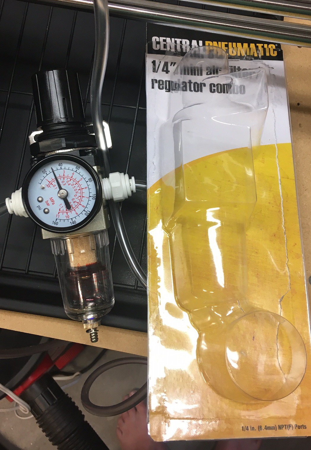
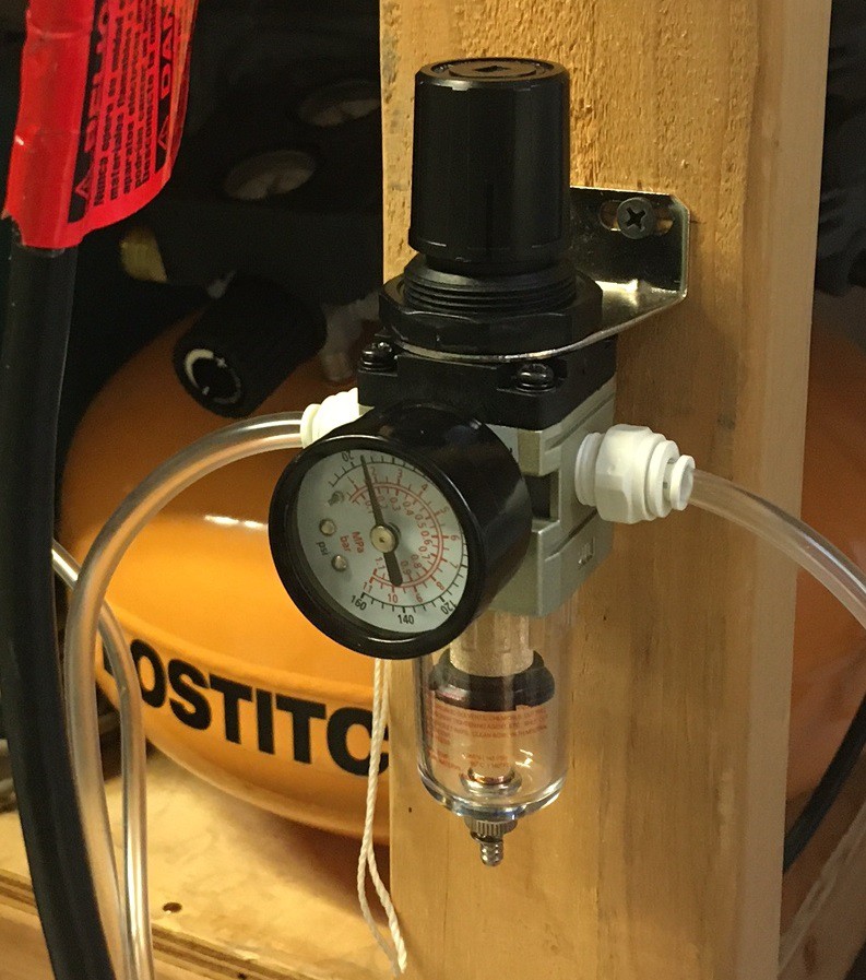
So I swung buy Harbor Freight and picked up a 1/4" air line filter and regulator for $15. This uses a diaphragm rather than a piston and has a lower psi range (5-120 psi). This is working really well, I opened up the regulator on the compressor to 90 psi and set this to 30 psi and it is only dropping 2.5 psi when I let the air flow through my nozzle. Interestingly the regulator on the compressor is still dropping 20 psi, but fortunately it is not affecting things down stream.
![]()
This should help a lot with precisely controlling the air flow going forward. It also has an air filter (of sorts) and acts as a water separator as well so that is a nice bonus. The air here is really dry so water is not much of an issue, but we do get humidity for a month or two. Anyway I'm looking forward to getting to really test this out soon.
-
Science!
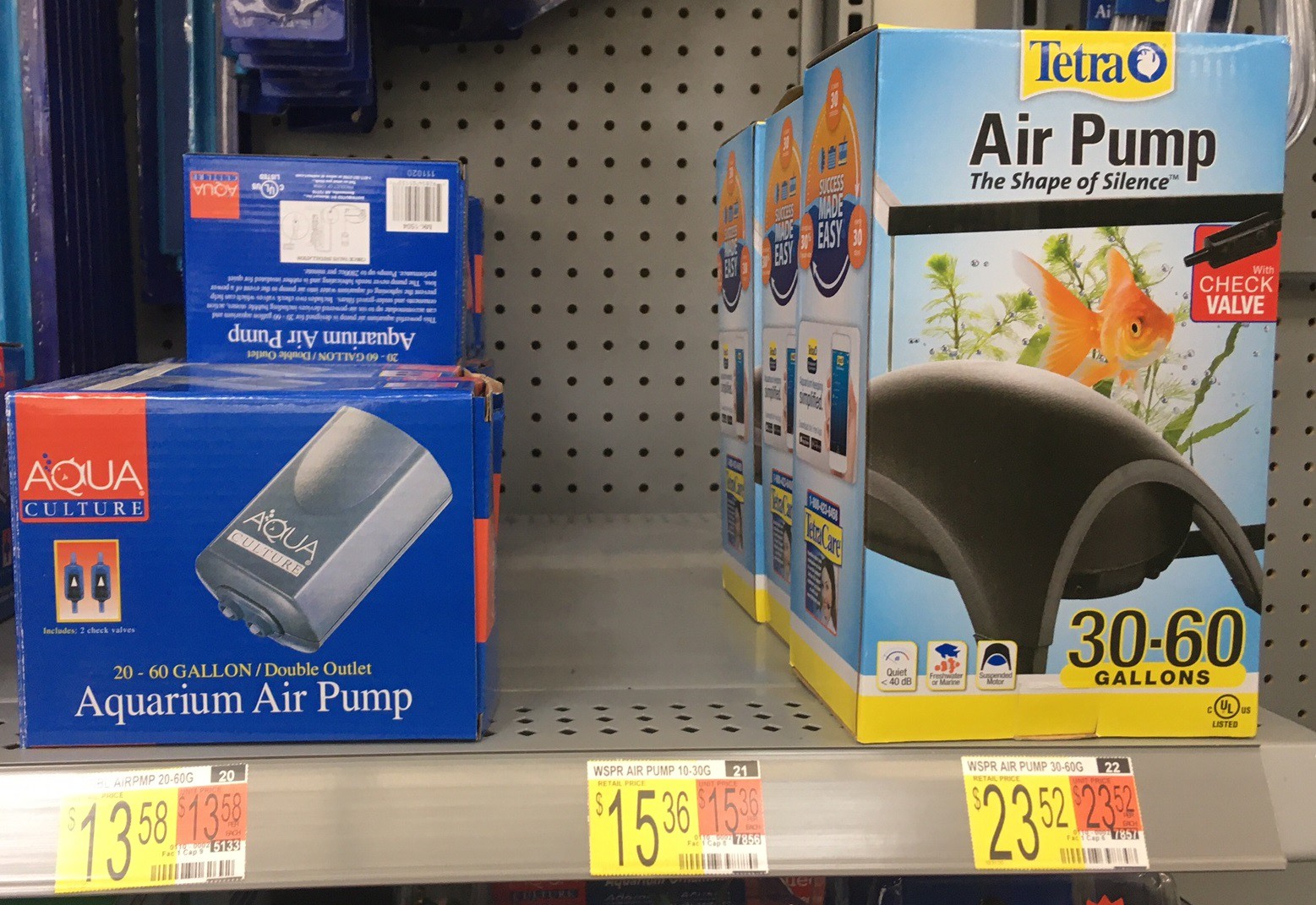
04/14/2021 at 04:14 • 0 commentsI dropped by Walmart and picked up two aquarium air pumps to test out. The cheaper Aqua Culture 20-60 gallon pump says 3.5 watt on the bottom of the unit. And the more expensive Tetra 30-60 gallon pump says 4 watt on the bottom. That is probably a relatively accurate way to compare there potential output. I brought them home and plugged them in and was soundly disappointed! Neither blew any harder than a medium breath, they are quite anemic.
![]()
Each have two ports and it appears each port is plugged into the opposite side of the pump. If you plug up one port the other one struggles to produce any air. Fortunately you can combine both ports and actually get more air out of them, but not a lot more air. I tested it out with my 2mm test nozzle and my over the lens nozzle. With the test nozzle there was a soft breeze, with the over the lens nozzle I could not feel any air at all. At first glance both pumps appeared to make the same amount of air pressure.
![]()
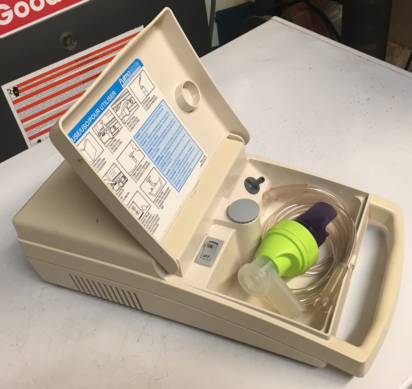
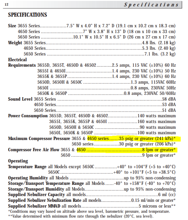
I remembered we have a pump for a nebulizer hiding in a cupboard. We have had this for a very long time but it gets used every once in a while so I can't repurpose it for the laser. However I wanted to test it to see how it compares to the fish pumps. This is a Sunrise (DeVilbiss) model 46502 compressor/nebulizer. According to the specs it draws 140 watts and it can output 35 psi and produces 0.28 cfm flow when the line has no pressure. Testing it out it works much better than the fish pumps. The air is not as fast or voluminous as my main compressor but it has a strong flow with both nozzles in place. The flow is about what you would get blowing through a straw. It is fairly loud, especially when the lid rattles around, but it is quiet enough for a workshop, and miles ahead of the pancake compressor.
![]()
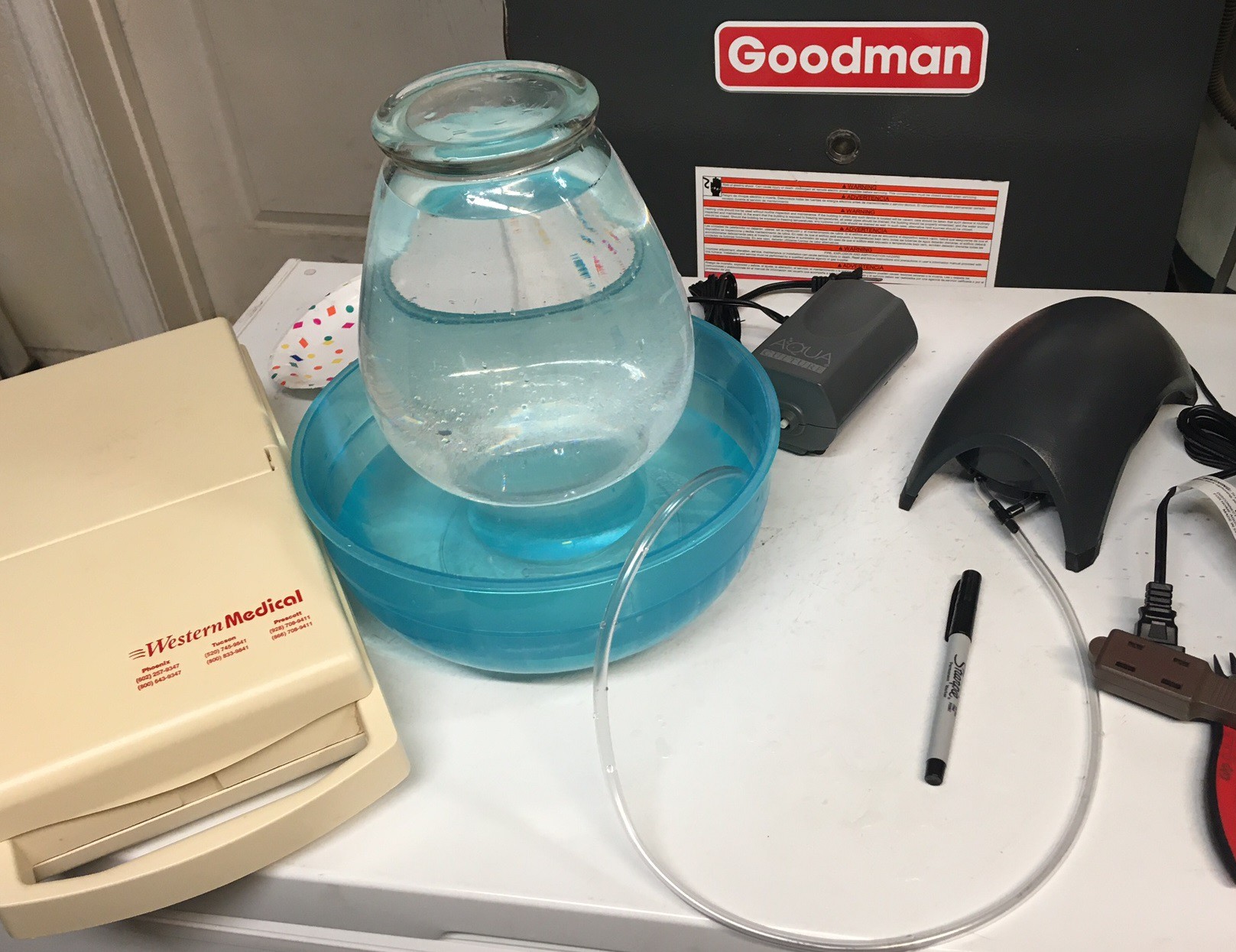
That got me thinking, how can we properly compare these pumps together. With the compressor we could measure how long it takes to build pressure in a tank, but these don't have a tank. It turns out we can invert a jar of water and bubble air into it to measure the air volume the pumps produce. If we also measure the time that this takes we can work out the CFM (cubic foot per minute) of the pumps. This measures the volume at zero pressure, the volume will be reduced as you continue to restrict the flow building pressure. It is an upper bound on the potential air flow.
We could test this under pressure by inverting the jar in a pool at a known depth. The pressure of the water above the jar will apply a known pressure on the air. However I don't have access to a pool...
![]()
Here is my test setup (I actually switched to a larger catch container later). I used the largest cylinder I could find (a vase), filled it with water and inverted it in a catch bowl. Then I marked the high water line and inserted my air tube into the inverted jar. I turned on the pump and measured the time to pump most of the water from the jar then marked the low line. Finally I filled the jar back up measuring the volume of water I added with a measuring cup. I tested all three pumps above along with my air compressor with the regulator set to 40 psi. The table below summarizes the results.
pump volume (ml) time (s) cfm Percent Aqua 2250 ml 34.4 s 0.14 cfm 10% Tetra 1800 ml 20.7 s 0.18 cfm 12% Sunrise 2200 ml 13.8 s 0.34 cfm 23% Bostitch 2050 ml 3 s 1.45 cfm 100% The (Bostitch) compressor measurement is suspect. The air pressure was so high and the flow so fast that it emptied the container quicker than I could reliably measure. I would need to repeat the test with a much larger vessel to get anything close to an accurate measurement. It is safe to say the air flow is much stronger than the fish pumps. Interestingly enough the compressor is capable of producing over 3 cfm of air, but were only seeing half that. I was running this through 50 feet of 1/4" tubing and running it through a ball valve, that may account for some of the loss in flow as well.
The data is interesting, but it does not paint the full picture. Because we are not measuring the flow under pressure the aquarium pumps are coming out better looking than they really are. I found that any restriction on the air tube with the aquarium pump severely restricted there flow. Probably a good backup test would be to measure the max pressure each pump can produce. I don't have a gauge accurate enough to do this, but I suspect the aquarium pumps can only produce a few psi at best.
Anyway any pump that can produce at least 0.34 cfm and at least 5 psi is bound to work. However that is probably the bottom of the range, I'm sure double those values would be much better.
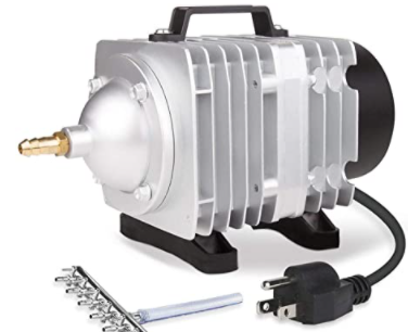
The large capacity metal aquarium compressors on Amazon claim to have plenty of cfm (0.7-3.9 cfm for $30-$100), however they are all very low on the pressure side (2.3-5.1 psi). I'm not sure if that is enough pressure to handle the restrictions in the line and nozzle. Anyway I may break down and pick one up, now that we have some tools to better compare them.
-
Pressure
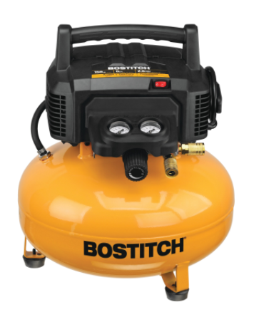
04/13/2021 at 02:47 • 0 commentsI'm really frustrated with my air compressor, it is just too darn loud! I have a Stanley Bostitch BTFP02012 6 gallon pancake compressor that is rated at 2.6 SCFM at 90 PSI with a peak pressure of 150 PSI.
![]()
The claim is that it produces 78.5 dBA of noise but that must be at 60 feet away in an open field. In my enclosed 2 car garage my dB meter is recording 92 dBA at 5 feet and my watch is sending me notifications that it is too darn loud. I don't run this without ear protection it is just too much. As a quick experiment I tossed it into a heavy duty cardboard box and closed the lid, mostly because it was easy to grab. That actually cut the noise by almost 10 dB but with the hearing protection removed it was still painfully loud, and much too loud to talk over.
I could try to build a small enclosure for the compressor and sound proof it. However this compressor runs very hot and I'm afraid it would be hard to get enough ventilation to keep the compressor safe while still reducing the volume by the 20 dB needed to bring this down to a manageable volume. Alternatively I could push the compressor outside and let the neighbors worry about the noise. However that does not sound like the neighborly thing to do, especially because I'm only 20 feet or so from my neighbors house.
That got me thinking about what my air needs really are. So I ran some experiments. First I drained the tank completely and timed how long it took to fill back up, taking readings at intervals of 30 psi. I came up with the following data. I used this CFM calculator to help with the math.
psi interval time(s) cfm 0-30 psi 14s 7.9 cfm 30-60 psi 26s 3.8 cfm 60-90 psi 33s 3.0 cfm 90-120 psi 37s 2.7 cfm 120-150 psi 44s 2.23 cfm I also calculated the cut in pressure at 120 psi and cut out at 150 psi. Interestingly enough refilling the tank from 120-150 took only 31 seconds (2.7 cfm), I suspect the faster fill time has to do with the fact the pump had cooled back down. Anyway from these numbers we can estimate that the compressor can produce 3.8 cfm at 30 psi and 2.7 cfm at 90 psi, that lines up well with the rated specs. It is always nice when that happens.
Next I used one of my 2 mm test nozzles and set the air regulator to 30 psi (with the air to the nozzle turned off). Opening the air it took 65 seconds to drain the tank from 145 psi to 120 psi, that works out to 1.3 cfm of air flow. Finally I put my over the lens nozzle on and re-ran the test with all that extra air leaking around the lens. That took 37 seconds or 2.21 cfm of air. I still need to see how long it takes the compressor to catch up when the nozzle is loosing 2.21 cfm of air, chances are it will basically be running all the time.
If I measured this right then I need something between 1.4 and 2.3 cfm depending on how well I can seal up the nozzle. CFM without pressure is a bit meaningless, it looked to me like the regulator was outputting around 10 psi with the nozzle in place and the air actually moving. That is much higher than the 5 psi that aquarium air pumps can produce, but I'm not sure exactly how all those relate to each other.
![]()
On paper this compressor could cover the flow rate. It is rated at 2.5 cfm at 4.3 psi and claims 60 dB volume all for $60. I'm a bit skeptical that it will live up to its given specs, and it would probably be better to have a bit of extra headroom just in case, so this compressor may be a better choice with 3.9 cfm at 5psi for $88.
Anyway these fish pumps probably have enough flow to get the job done, and the rumor is they are quieter than a proper compressor. They would be running at or near there limits the whole time you are cutting, but they should get the job done. Keep in mind that my compressor could go much higher than 30 psi, we could easily get a lot more air out of it. There is an upper limit on this however, eventually you need better quality tubing and connectors just to keep it all together. I experimented with 60 psi and my system popped apart.
I'm going to investigate plugging up the lens side of the nozzle to reduce the air loss. If nothing else that will give my compressor a bit of a break so it is not cycling quite as often when cutting. However the pressure is rather intense, I found it difficult to plug the hole up with my thumb when I took the nozzle off the laser, I'm not sure if a bit of silicon will hold together.
-
Baltic Birch
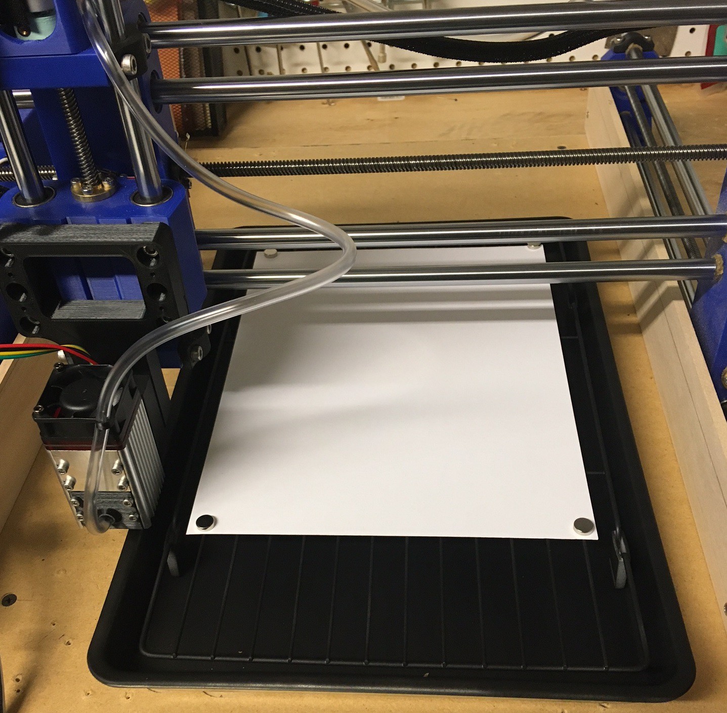
04/10/2021 at 02:09 • 0 commentsI have some1/8" (3mm) Baltic birch from woodcraft that I thought I would test cut with the laser today. This is truly 1/8" so it is more like 3.2 mm and is 3 ply.
![]()
Anyway I wanted to see how well I could cut it with and without air assist. I did some initial cuts into the side of it at 100-400 mm/min and 75% power with full air, however none of those really made it through. So I tried again at 80% power and speeds of 25-100 mm/min and full air and this time I made it through nicely.
Next I wanted to see how important the air assist is so I ran the job again with no air and then with the air set to a light trickle (just barely making any noise). You can see that no air is a disaster waiting to happen, I don't think you should go near wood with a laser that does not have air assist. Light air faired a bit better but you really need the speed to keep it from burning. Neither cut very deep and the cut has a lot more taper to it.
![]()
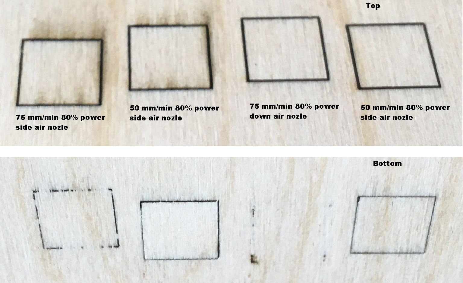
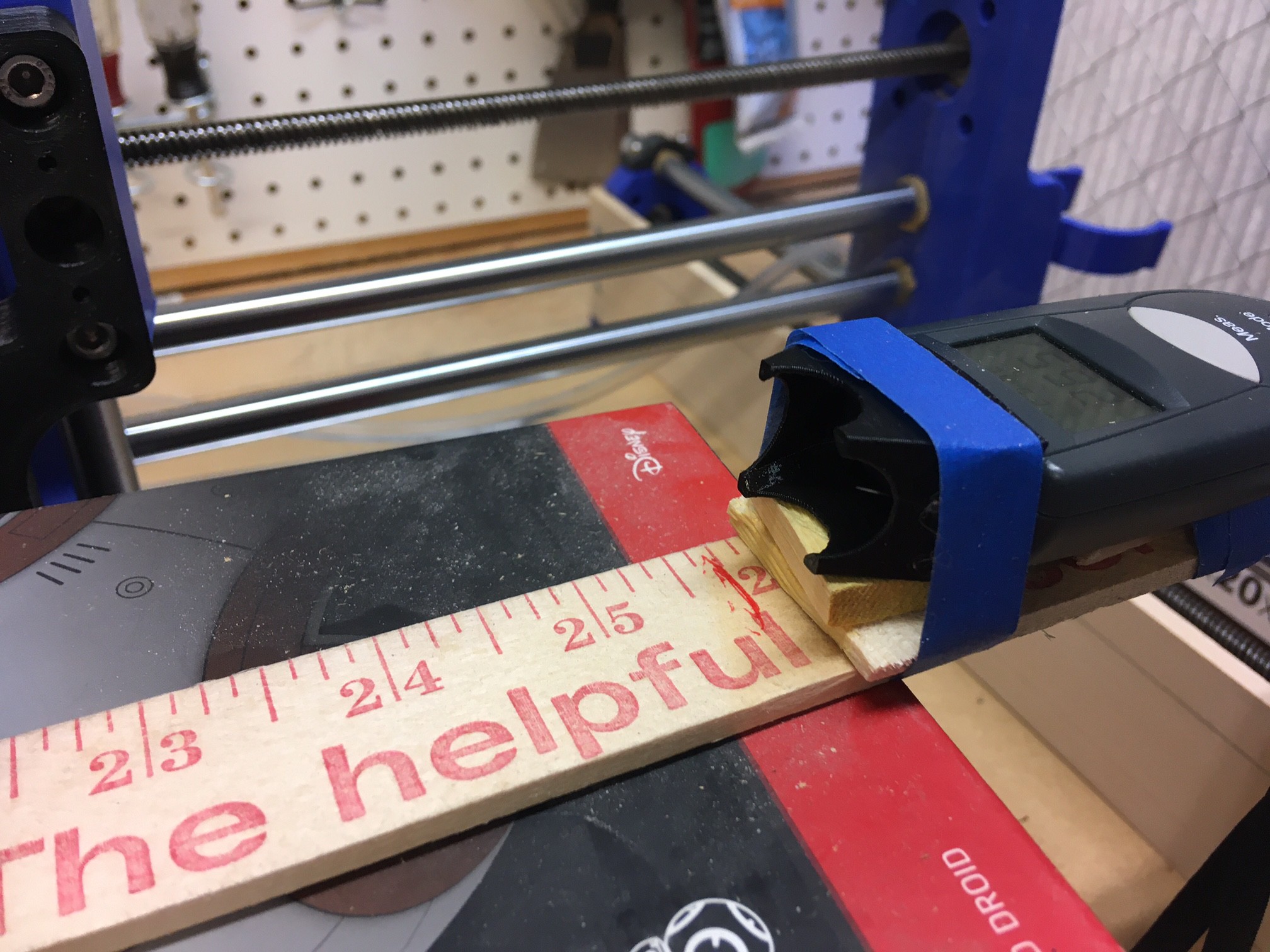
Next I wanted to compare my two air nozzles, the one that is mounted next to the lenses and blows in from the side vs the one that mounts over the lens and blows straight down into the cut. I also wanted to verify what speed would successfully cut through my wood in one pass. It turns out 50 mm/min at 80% power can cut through in one pass. That is not setting any sort of a speed record, but it is not bad.
The side air nozzle is a bit of a dud. It is working way better than no nozzle but it is blowing a lot of smoke across the work in the direction the nozzle is aiming (towards the top of the piece in this case). The downward air nozzle produced less smoke and appeared to have less of a flair up as well. Visually it appears the width of the cut is smaller as well.
I'm still contemplating ways to seal the over the lens nozzle around the lens, I'm not sure if that is worth the effort or not. Maybe it is time for some experimentation. But I will be sticking with the over the lens nozzle going forward. Having a loud compressor run is not as bad as a smoked out cut.
This basically confirms what we already knew. To cut wood you need a lot of air blowing straight down into the cut to clear away all the burnt material. And it highlights another point, this is very much like trying to cut wood with a soldering iron, it is a serious fire hazard and all safety precautions should be followed at all times. Most importantly don't turn your back on the cut, it can flair up really fast.
-
Danger!
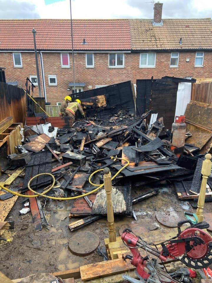
04/09/2021 at 03:02 • 0 commentsIt's time to talk safety again. A member on one of the laser forums I follow posted this picture of there shed recently (I hope it's just there shed). They left there laser (k40) unattended for a moment and something went terribly wrong. Everyone is ok but they did spend some time in the hospital.
![]()
Anyway the point is that lasers and cnc machines are dangerous. Not just in the lose your eye sort of danger but fire and plenty of other risks. This is not something to goof around with. You need to treat it like the scariest saw in the shop. In fact it is far worse than that because it is automated and will continue to cut or burn long after something goes wrong.
- Always stay close to your machines when they are running. You should be able to smell the smoke, or hear the broken bit as soon as it happened. Don't rely on a baby monitor or camera to monitor, and never leave things unattended even for a moment.
- Be wary of anything on the machine that can detach and become embedded under the laser or cutting tool. This includes air assist nozzles. My design bolts to the laser head, I would not want to risk a friction fit.
- Don't push the machine too hard, loosing steps can lead to tools being trapped in the work. In fact anytime the laser or cutter is in continuous contact with any object you are at a high risk for fire.
- Always wear safety gear. A laser light can bounce off of anything and even an unfocused light can start a fire or blind you. Your ears, eyes and mouth all need protection at all times.
- Don't ever power up the laser when it is just resting on the table. It is too easy to accidentally bump it and have it spin around. The laser should be well secured at all times.
- Make sure your machine is properly maintained with all cables tied up and everything well secured.
Safety is no joke. You need to use your brains when building this machine. It is not my job or anyone elses to keep you safe, that falls squarely on your shoulders. And it goes without saying but my instructions above are only a guide to how I build my machine, I am not responsible for any harm you may cause to yourself, others, or your property. Keep safe!
-
Lightburn Take 2
04/07/2021 at 01:54 • 0 commentsSo lightburn is a frustrating app. It is so close to being great, but out of the box it does not work well with GRBL and I can't see a good reason for it. All the other GRBL senders just sense how the machine is setup and work with it, but not lightburn. Anyway after lots of frustration I stumbled onto this document on there website for how to make your grbl machine work. After spending some time playing with it I came up with the following adjustments and it seems to be working properly now.
![]()
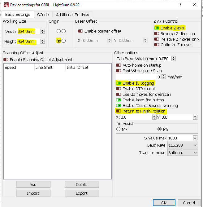
First in the device settings fill in the following options:
- Our machine dimensions (about 350x450 mm), be sure to measure this accurately from the home position for your machine.
- Set the origin to the lower left corner (even though our origin is the upper right)
- Enable z axis support
- Enable the $J jog mode for smoother jogging.
- Turn off return to finish position, unless you have a safe position you want to send the cutter to.
![]()
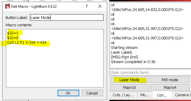
On the console tab we need to add in two macros. One will put the machine in laser mode and the other will return it to mill mode for regular mill work. We will send $32=1 to enable laser mode, this has some laser safety like not turning the laser on unless the head is in motion. And it removes a motion delay when you change the power. $10=0 sets the machine into relative coordinates. And G10 L2 P1 X-334 Y-334 offsets the origin relative to our home position so the origin is now in the lower left corner of the workspace.
![]()
Mill mode just reverses the above by turning off laser mode, using absolute coordinates, and removing the origin offset.
When you first start up lightburn, hit the home button, then hit the laser mode button to set the origin correctly. Then at shutdown hit the mill button before exiting.
![]()
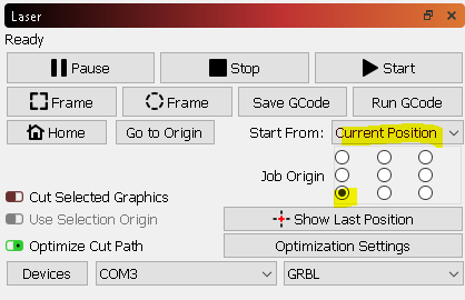
Finally for your job control set the origin of the job to the lower left corner and the start position to the current position. That way you can jog to the corner of your work and start a job. Keep in mind that by default this will start cutting at the current head position. There may be a better way to handle this, I need to experiment some more.
If you want when jogging you can also enable continuous jog mode so that the laser moves as long as you hold down the jog buttons. This works out ok, but the default move is very small so it can be fiddly to try and zero in on a point.
Anyway these changes seem to take us from broken to just a bit annoying. Still I wish they had a more intuitive setup out of the box for GRBL.
-
Misc.
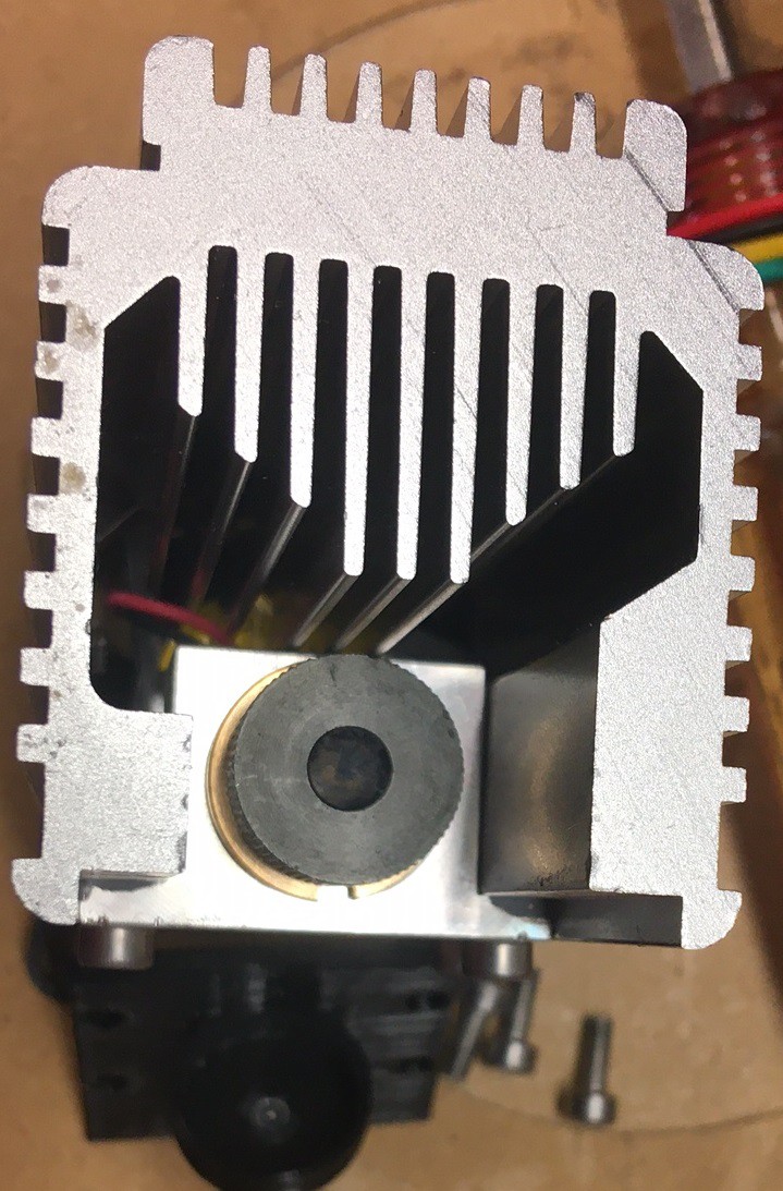
04/06/2021 at 05:08 • 0 commentsI have always wondered why the new 40w module from NEJE cost more than twice that of the 30w module, when the 20w module is only about $10 cheaper than the 30w module. Well I was poking through the neje.shop website and came across a video where they disassemble the laser.
It turns out that they are using two laser diodes with a beam splitter to combine the output back together. That makes it plausible that they are getting 15w out of the diodes, assuming the diodes were 6w and overdriven by 20% or so.
![]()
I also painted my bed mat black to reduce the flashback and make things a bit more safe. It works better than I would have though. We will see how long the paint lasts but I think it was worth the effort.
![]()
-
Laser Calorimeter take 2
04/04/2021 at 18:44 • 0 commentsSo my previous laser calorimeter topped out at 50% because it could not handle the heat. I was eating a bowl from Chipotle and noticed that the tin lid was a nice compromise between too thin and too thick so I thought I would try swapping it in to my rig in place of the tinfoil. That worked great, and I was able to get readings from across the full power range.
![]()
It is not shown in this picture but the foil is taped onto the points of the holder with tiny pieces of double sided tape. If I made this again I would have the foil slide into the holder rather than mess with tape...
![]()
![]()
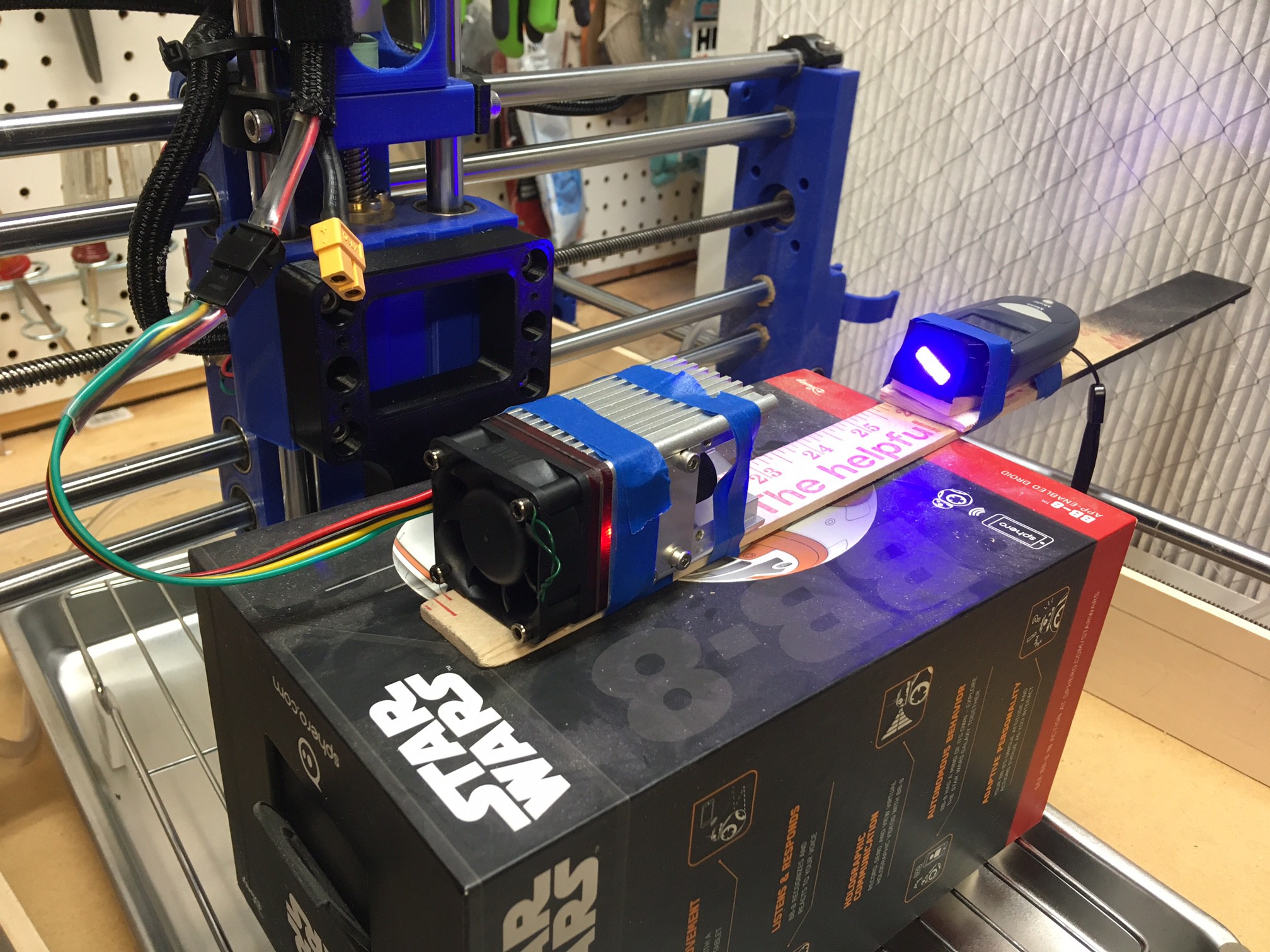
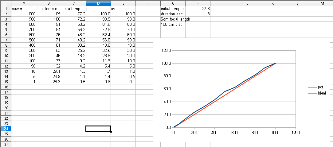
I used a 20mm square piece of the lid painted flat black. I mounted it 100 mm away from the laser with the laser set to a 5mm focal length. That spread the beam across almost all of the target surface and minimized the chance of hurting the target. I then placed my IR thermometer about 8 mm behind the target and placed it in continuous mode. Using my test program I triggered the laser for exactly 3 seconds (+/- 1 ms) and read the temperatures by hand from the display. Reading the temps is the biggest issue, the display updates probably 10 times a second, so the accuracy is not great. The thermometer has a max mode, I should experiment with that, but I would need to find a way to hold the button down for that to work.
![]()
Anyway the results look as linear as the previous ones. This is surprisingly linear across the whole power range. I was expecting some serious degradation at the top since we are overdriving the laser. I would still stay away from 100% power to try and extend the life of the laser.
-
Better air nozzle
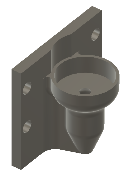
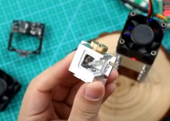
04/02/2021 at 04:57 • 0 commentsA while ago I made an air nozzle for my laser. This replaced the red shield on the front of the laser and completely enveloped the lens so the air is flowing in the exact same direction as the beam. This worked really well except for one issue, more air leaked around the lens than came out of the nozzle. I could try to seal things up at the lens side of things but I worry that is just going to make a mess and be difficult to reattach when servicing the laser.
![]()
![]()
![]()
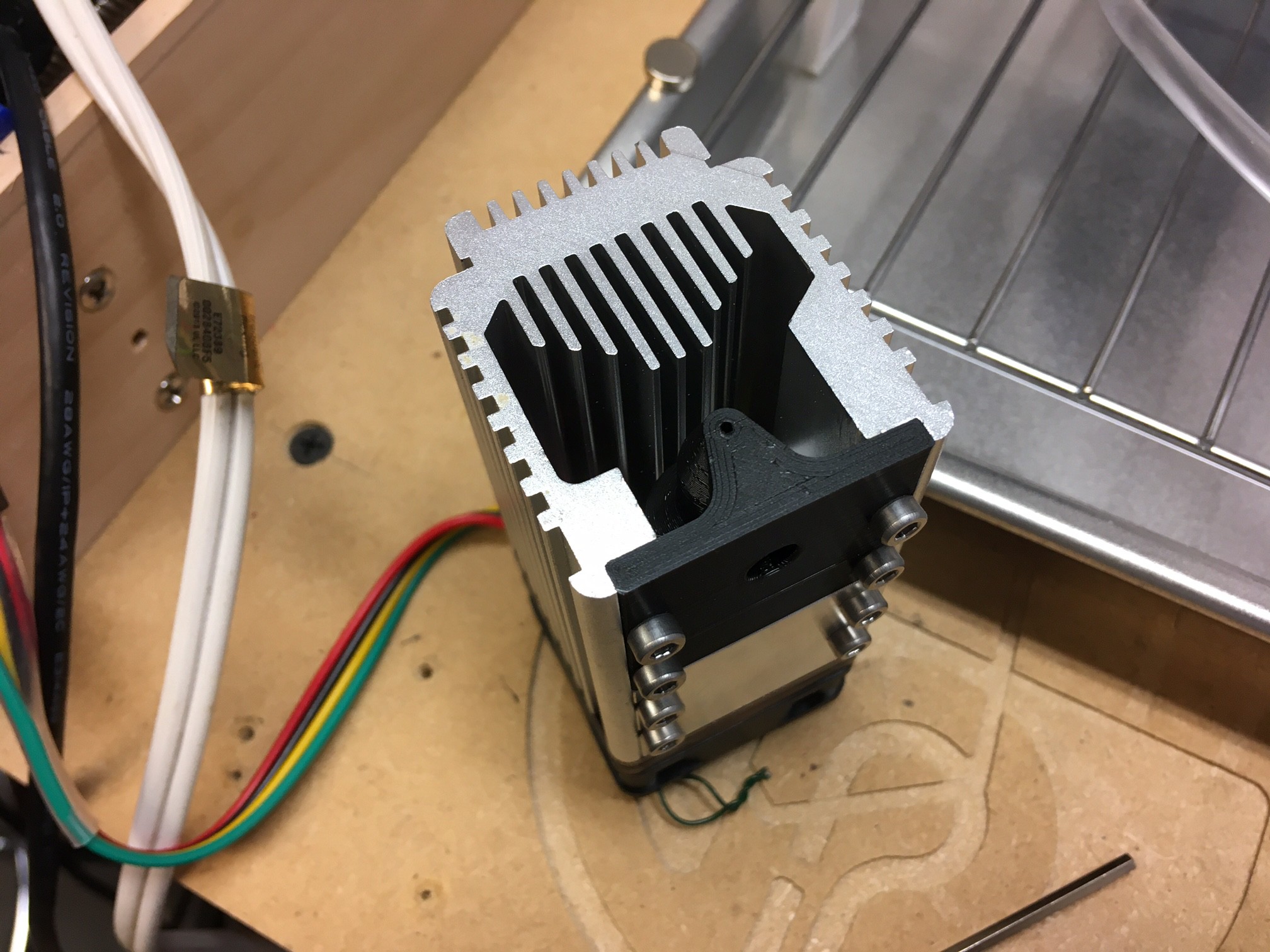
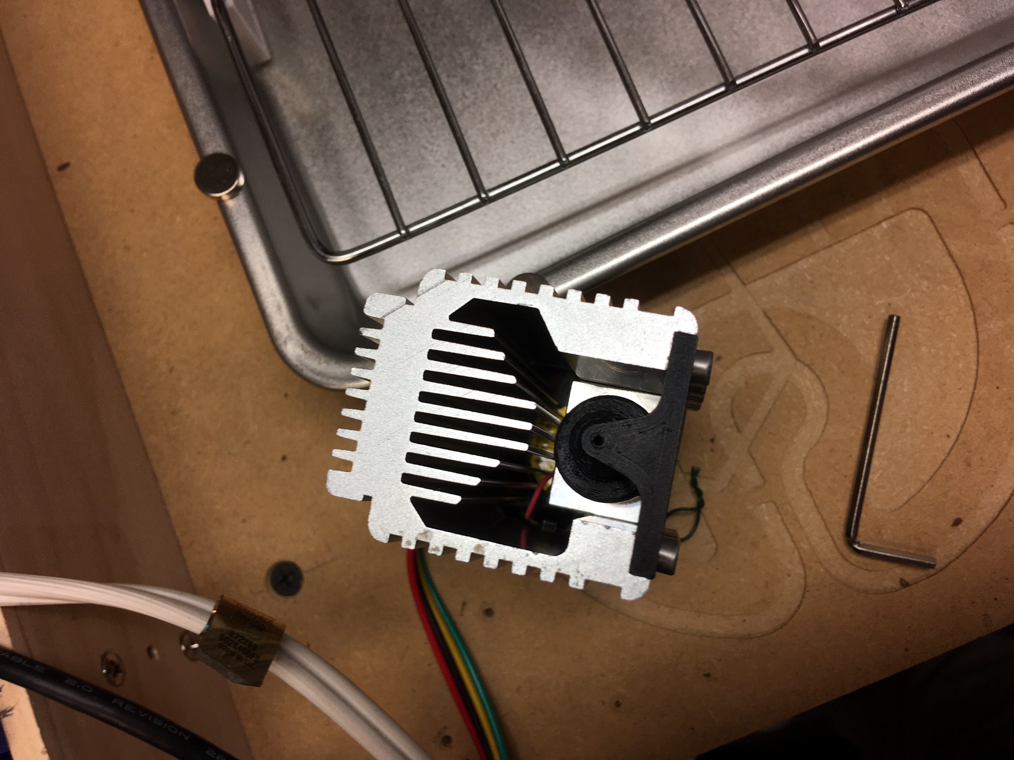
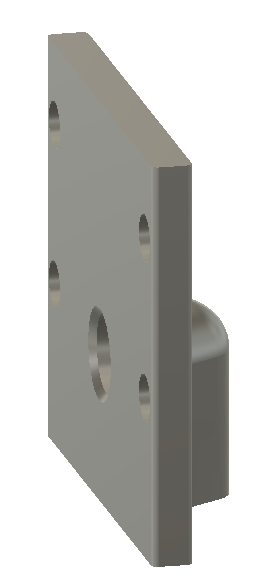
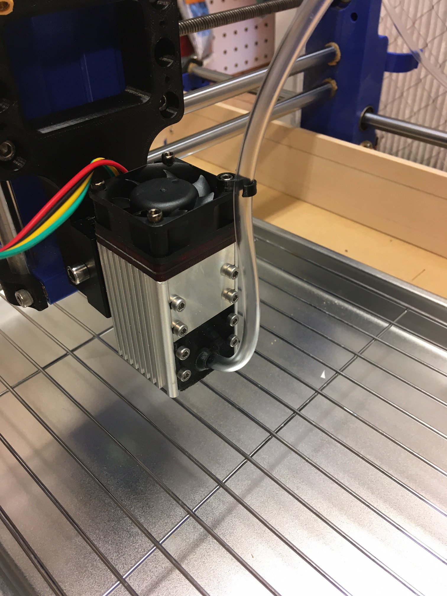
So I decided to redesign this again using a nozzle that runs close to the beam but not quite in the same direction. This is not as good air wise but hopefully it will help keep my compressor from cycling so often and should allow me to use more pressure. It is not clear in the rendering but the nozzle has a bit of an angle to it internally, that seems to be just enough to push the center of the jet over the center of the cut at a distance of 5mm from the end of the housing.
![]()
![]()
![]()
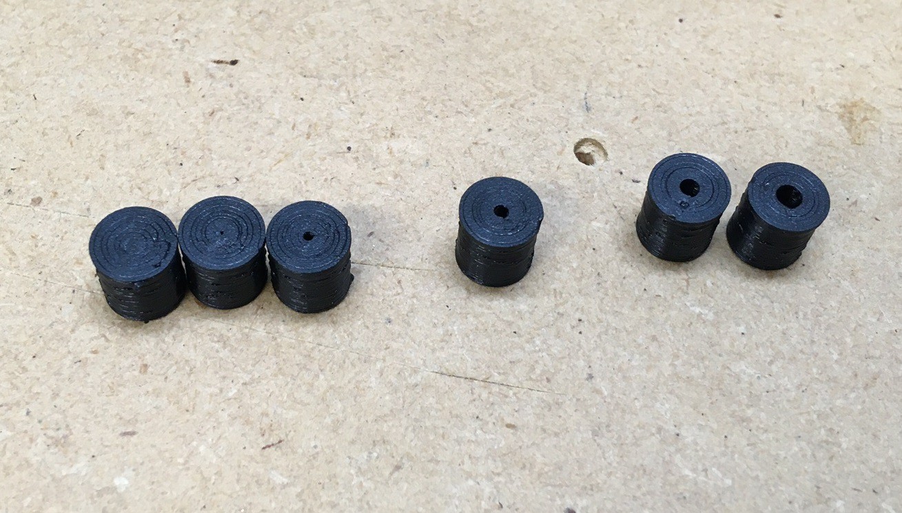
At the same time I made a series of test nozzles with various size holes in them to see how the size affects the air flow. I printed sizes from 0.5mm to 3mm in 0.5mm steps and found that the 2 and 2.5 mm holes produced the best results. At 3mm the air flow was spread out too much and unfocussed, and at 1 mm it was severely restricted with much lower flow and pressure, 1.5 mm was ok, but 2mm had a detectably stronger flow.
![]()
MultiBot CNC v2
A low cost 3D printed CNC that can be built with minimal tools yet is capable of great things.