David Tucker
-
Backlash
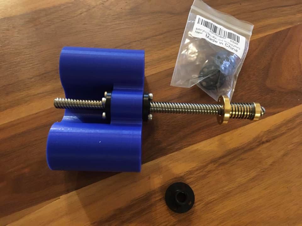
12/03/2020 at 02:44 • 0 commentsI have been struggling to eliminate backlash and think I hit on the solution.
I have tried two brass nuts but that was really difficult to get the tension right. A quarter turn is the difference between to loose and binding up.
Backlash nuts feel better at first but they are easily overcome under load. Plus they make a lot more noise and they add a lot of drag for the motors to overcome.
I recently tried delrin nuts (well imitation ones from amazon). They have much tighter tolerances out of the box and you can more easily double them up. It is still easy to bind it up with two so consider shimming the nut if you do this.
I’m not sure how long they will last but so far the are great and the price is right.
![]()
-
Heat set inserts take two
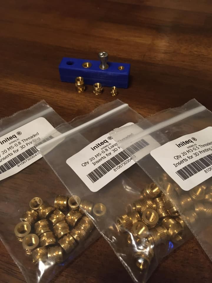
12/03/2020 at 02:41 • 0 commentsJust a follow up to my last insert post. I picked up some quality inserts and they work so much better than the cheap amazon ones.
The longer 12mm m5 insets take so much heat that they caused a lot of warping of the model. But the shorter 6mm inserts went in with minimal warp. Less is more in this case.
I picked mine up from initeq
![]()
-
Heat set inserts take one
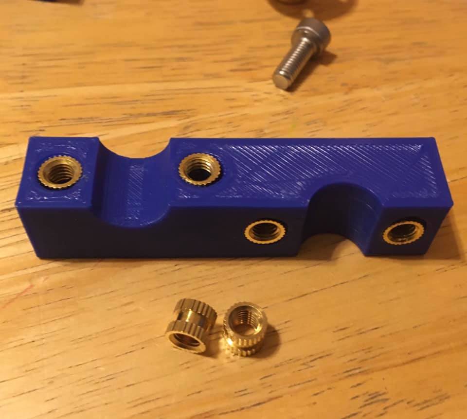
12/03/2020 at 02:39 • 0 commentsI have been experimenting with threaded inserts to see if they can be used to add strength to my build. However so far the cheap ones from amazon are proving to be fairly useless. No matter how carefully I insert them, they drift a bit to the side leaving a gap between the plastic. With there poor registration I’m seeing an offset of 2 mm at times. It is possible that the higher quality ones would set better...
![]()
-
Visualizing flex
12/03/2020 at 02:37 • 0 commentsI’m still waiting on my lead screws so I thought I would run some more strength tests. I wanted to remove the rod lengths from the equation so I reconfigured my machine to be as small as possible and then applied horizontal loads at the tool tip in x and y.
Without lead screws I had to print clamps to fix the carriages to the rods. That is not a very valid test since the true force is at the lead screw coupler but it did validate the approach.
I wanted a way to visualize the flex so I took two pictures, one unloaded and one with 12kg of load (the max my motors can produce) and created an animated gif that flickers between the photos to show the change.
Anyway I need to rerun this test once I have the screws in place but it shows good potential.If you can't see the animations, click on these links.
https://drive.google.com/file/d/1WCDO56HmuPtjiAbYbI8hDq9x1OoLgzZW/view?usp=sharing
https://drive.google.com/file/d/11k9zTuHS4Xlt9F1XTvrYqrfzLlFwhm-s/view?usp=sharing
![]()
![]()
-
Scaled up load test
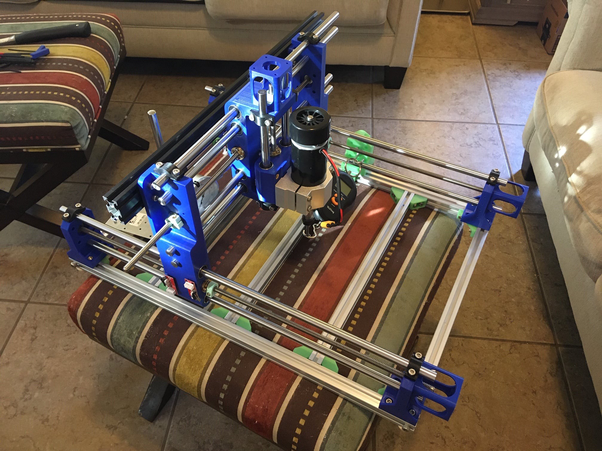
12/03/2020 at 02:33 • 0 commentsI’m still waiting on some parts so I’m continuing to test with the parts I have. Since I’m missing some lead screws and extrusions I decided to make some clamps for the 12mm rods so I can continue my strength testing. I only have 400mm extrusions so far so the setup is basically a square.
Applying a 12kg load to either the x or y axis at the tip of the tool (using a nail as a stand in for a bit) I’m measuring 4mm of flex in either direction. Interestingly in the y direction I’m also measuring 4mm of movement on the z axis. Basically the x axis is twisting from the offset load.
It appears the flex is almost completely in the rods. It is the weak point in the design.
Anyway this was a really rough test. It is possible the nail is flexing more than I thought. I need to run it again while measuring at more points to verify where the motion is coming from.
![]()
![]()
-
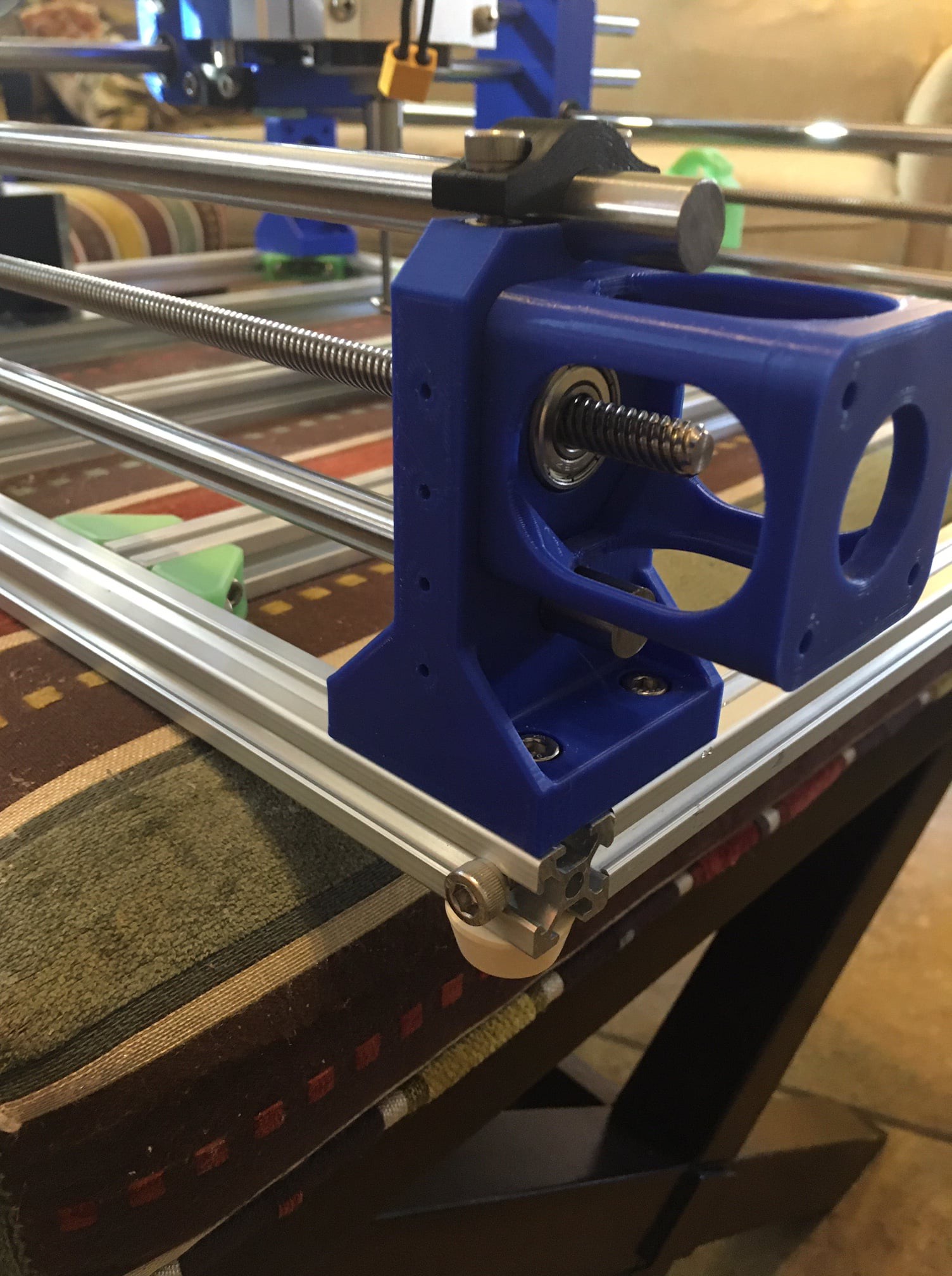
Dual rail deflection
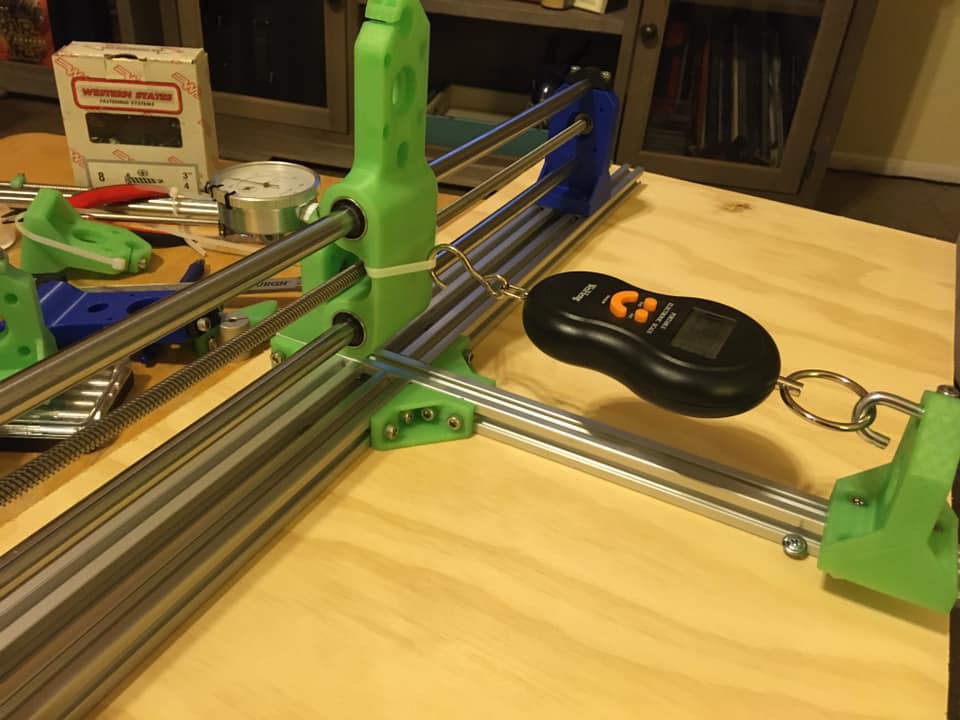
12/03/2020 at 02:31 • 0 commentsThere was some concern about my last rod deflection test (not shown here) so I ran it again in a more true to life setup. I used two rods and LM12LUU linear bearings along with a lead screw for good measure. I also mounted the test rig to a piece of plywood to ensure there was no flex.
The flex was greatly reduced and it appears more linear in nature. I think mounting the rig to a solid base provided the biggest improvement.
I can still get a lot of flex just by pulling on the top of the y carriage. I measured a full cm of motion at the top. I suspect a solid mount between the y carriages would help a lot with rigidity as well.![]()
![]()
-
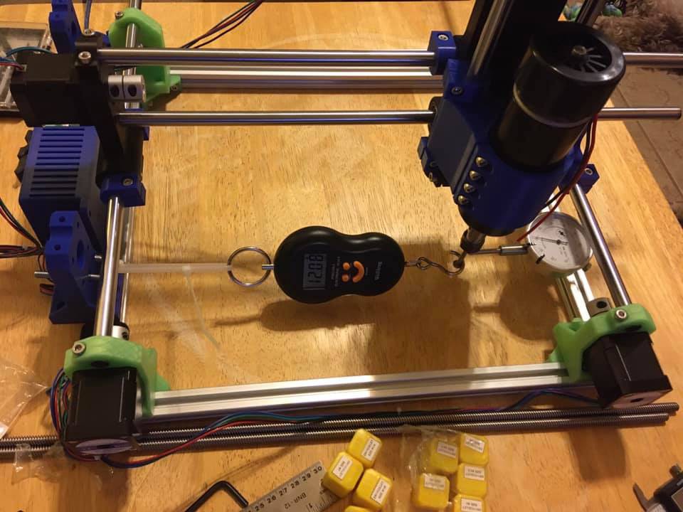
Peak force test
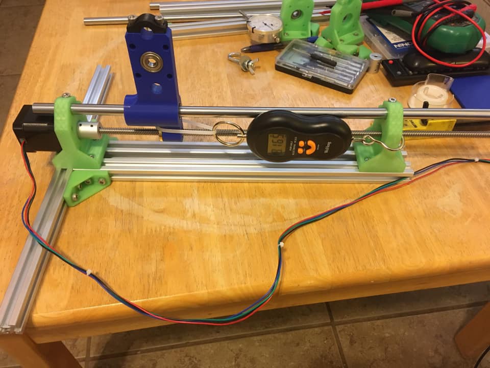
12/03/2020 at 02:26 • 0 commentsI was curious to know the max force my cnc could produce so I came up with this test rig. Using the DRV8825 driver at 2 amps (vref 1v, 0.31Nm measured torque) and a 8mm pitch lead screw, I’m measuring a peak force of 12kg. My stepped motor claims a 0.59Nm peak torque, in theory that could yield 23kg of force, however I don’t have drivers that can sustain the current needed to produce that torque.
---
After my last test someone asked me about micro stepping. Since I still had the rig setup I ran my tests again at full, 1/4 and 1/16 steps.
At full steps the rig measured 12kg of force but was not running smoothly, the motor tended to overshoot on each step.At 1/4 step I measured 13kg of force and the steps were much smoother.
At 1/16 step I measured 12kg again.
From these results I would not turn off micro-stepping but I would set them as low as possible to achieve the smoothness you need.
![]()
-
Motor driver torque test
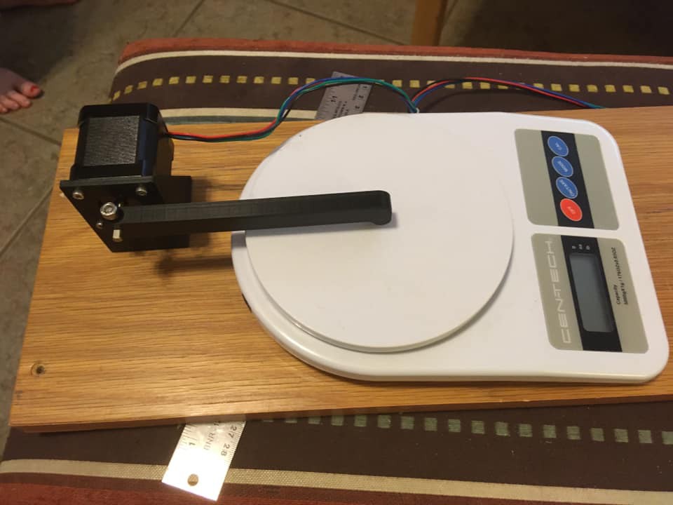
12/03/2020 at 01:29 • 0 commentsI wanted to compare different motor drivers together to see if we could maximize the torque of our motors. Here is a picture of my test rig and the results. The A4988 driver is a good starter driver. Even at peak current it did not run too hot. It peaks out at 1.7 amps however.
The DRV8825 driver can produce the most torque but it runs extremely hot at 4 amps, it would be difficult to get enough cooling to run it much past 2 amps. It is also the most noisy of the bunch.
The TMC2208 has very poor holding torque and is unsuitable for a cnc machine. It would work just fine for a pen plotter or 3d printer.
The TB6600 runs cool even at max current, but you could easily match the force output with the DRV8825 with less fuss. I’m disappointed in this one, it lacks umph.This is all with 52mm 2A Nema17 stepper motors from AlliExpress being driven at 24v 3A power supply.
Note that my power supply was only 3A, it is possible the TB6600 driver could produce more torque in its 4A setting with a larger power supply.
![]()
![]()
-
Test of rod stiffness
12/03/2020 at 01:26 • 0 commentsI posted most of my logs to a Facebook group, I'm going to copy them over here for posterity (so be honest!) Here is a log on testing I did to my v1 machine to see if more rods or a stronger x axis would help stiffen up the machine.
---
I have been trying to stiffen up my machine and have made some progress.
First I had not originally tapped the aluminum profile for the base but it turns out this adds much more strength than the corner brackets. However even with this the frame is not very solid, I'm going to convert over to using a 1" plywood base, it is much cheaper, simpler and stronger.Next I made a Frankenstein rig to test out various ideas. I doubled up the 12mm rods on the x and y axis and added in a 4020 aluminum profile to anchor the two y carriages together. Then by removing parts I was able to test the relative benefit of each addition.
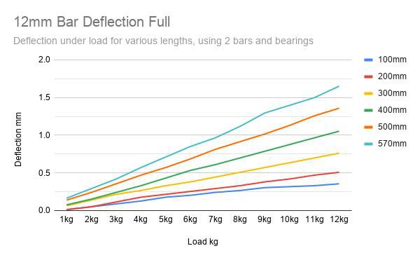
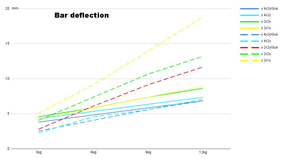
I setup my dial indicator on the x carriage measuring deflection in the x and y axis. I did not measure deflection at the tip of the tool because I wanted to only detect the benefits of the extra strengthening of the x and y axis and did not want any extra noise.In the attached chart you can see the x and y deflection with 4 or 2 rods on the x axis, 2 or 1 rods on the y axis, and with or without the 4020 profile attached. You can see that the 4020 profile has almost no benefit at all. It is possible that tapping it and mounting it via the ends would have a small extra benefit but I doubt it.
Doubling up the x and y rods has the most benefit, but doubling the y rods alone has a rather large benefit on its own, especially in the y direction. I suspect that in the x direction the extra y axis rods actually reduce lay over of the uprights.
Honestly going with 16 mm rods would probably be a more cost effective and stiffer solution. There is still a visible amount of deflection to be had just by pushing on the x and y rods individually. It is something to experiment with later, but for now I will see how far I can take things with what I have.
Oh and spacing the x axis rods out seems to really tighten things up as well.
Finally to reduce backlash I used a brass nut on one side of my carriages and a Delrin nut on the other. Putting pressure on the Delrin nut to take up the play. This has made a big difference and works much better than the cheap anti backlash nuts you see on alliexpress. I figure using both materials is safer, the brass will act as a backup if the Delrin fatigues.
I need to take these ideas and redesign the rig, I have too much z height for starters. But at least I have a better understanding of the relative benefits of each change.
![]()
![]()
![]()
![]()
![]()
MultiBot CNC v2
A low cost 3D printed CNC that can be built with minimal tools yet is capable of great things.