David Tucker
-
Art
06/18/2022 at 22:06 • 0 commentsI was wandering around the dollar store the other day and noticed they have added in a lot more hobby level supplies, probably so they can compete better with 5 below. Anyway I wondered around for a bit and picked up a pile of new materials. I have some circuit vinyl decals (for the mat knife), some fabric squares, felt squares, a cheap glass picture frame, a great 12" square piece of plywood that was made into a canvas, and 3 different $1 paint canvases.
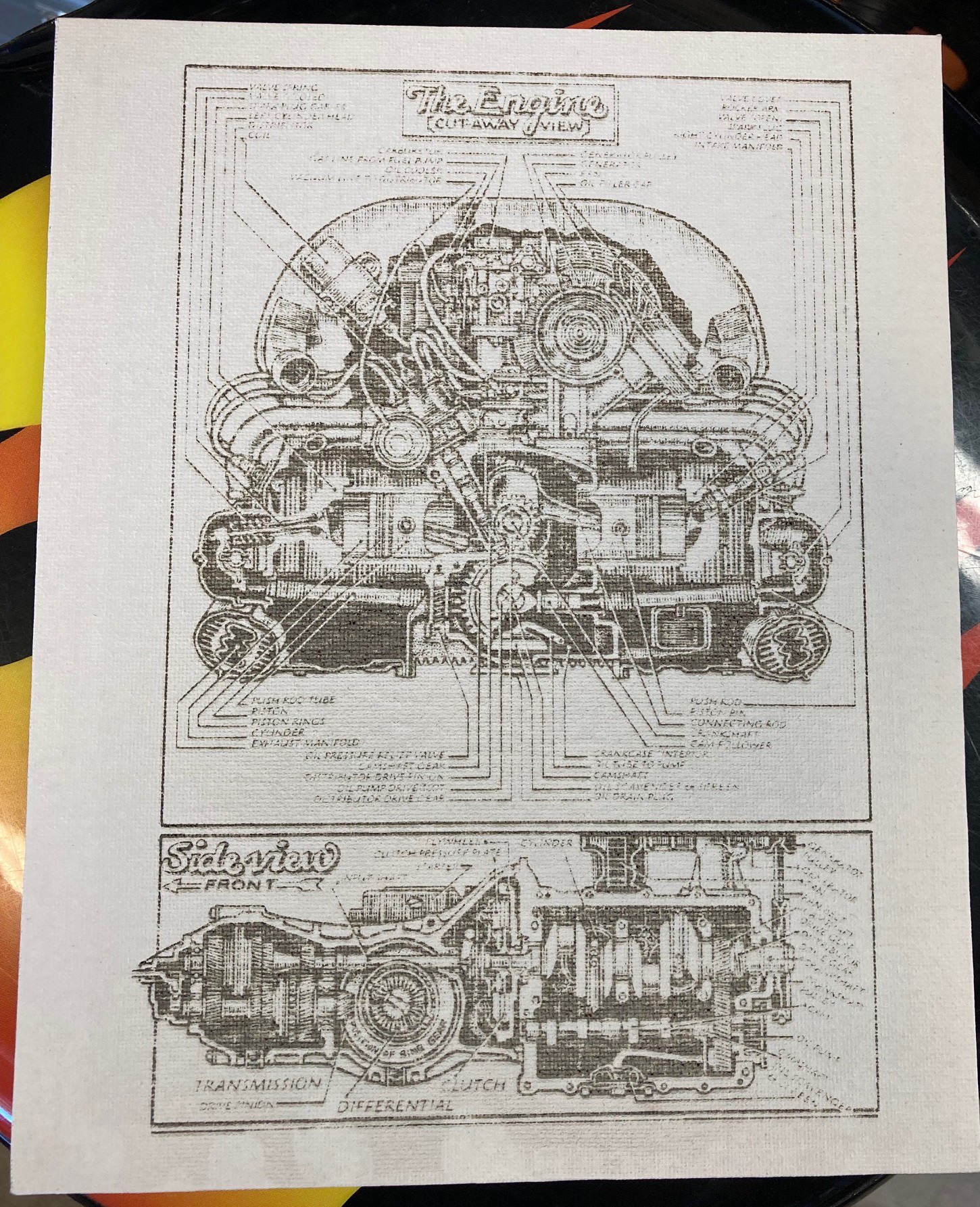
I'm a huge fan of John Muir's book How to keep your Volkswagen alive forever. Not only is it a fun read, it has some amazing images by Peter Aschwanden. I pulled out my copy and scanned in some of my favorites.
I then used the trace feature in lightburn to convert the scans into vector outlines. These are not my images, so I won't post the svg's here, but they turned out great.
![]()
First up I tried engraving on the canvas. It was really tricky to set the power here, the distance between no marks and burning through the canvas is only a small percent of power. I ended up engraving at 4000 mm/min and 75% power. The larger details look fine, but thinner details like the text were washed out.
![]()
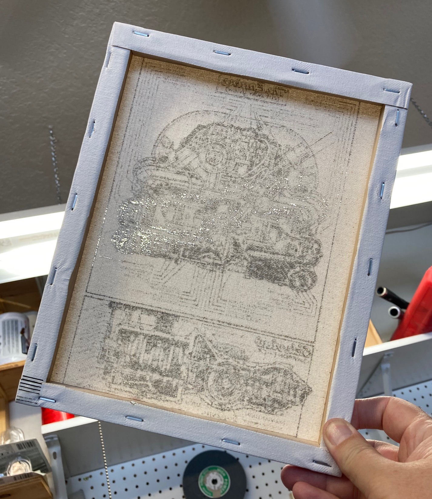
More importantly, if you look at it through the back side you can see that the material is burned all the way through, and there are large areas where the light passes right through. I suspect I could rip this without much effort. This also took a long time to run, almost 2 hours.
I have a few more canvases to experiment with. I'm going to try painting them with white paint to thicken up the material, and hopefully the paint itself will discolor without burning through, giving a darker image in the process. I'm also thinking of using a larger step size for the line so there is less overlap between lines, I think that is part of why I cant get a darker cut. Finally I used air on this, but turned it down a lot so it was just moving enough air to keep the lens clean.
![]()
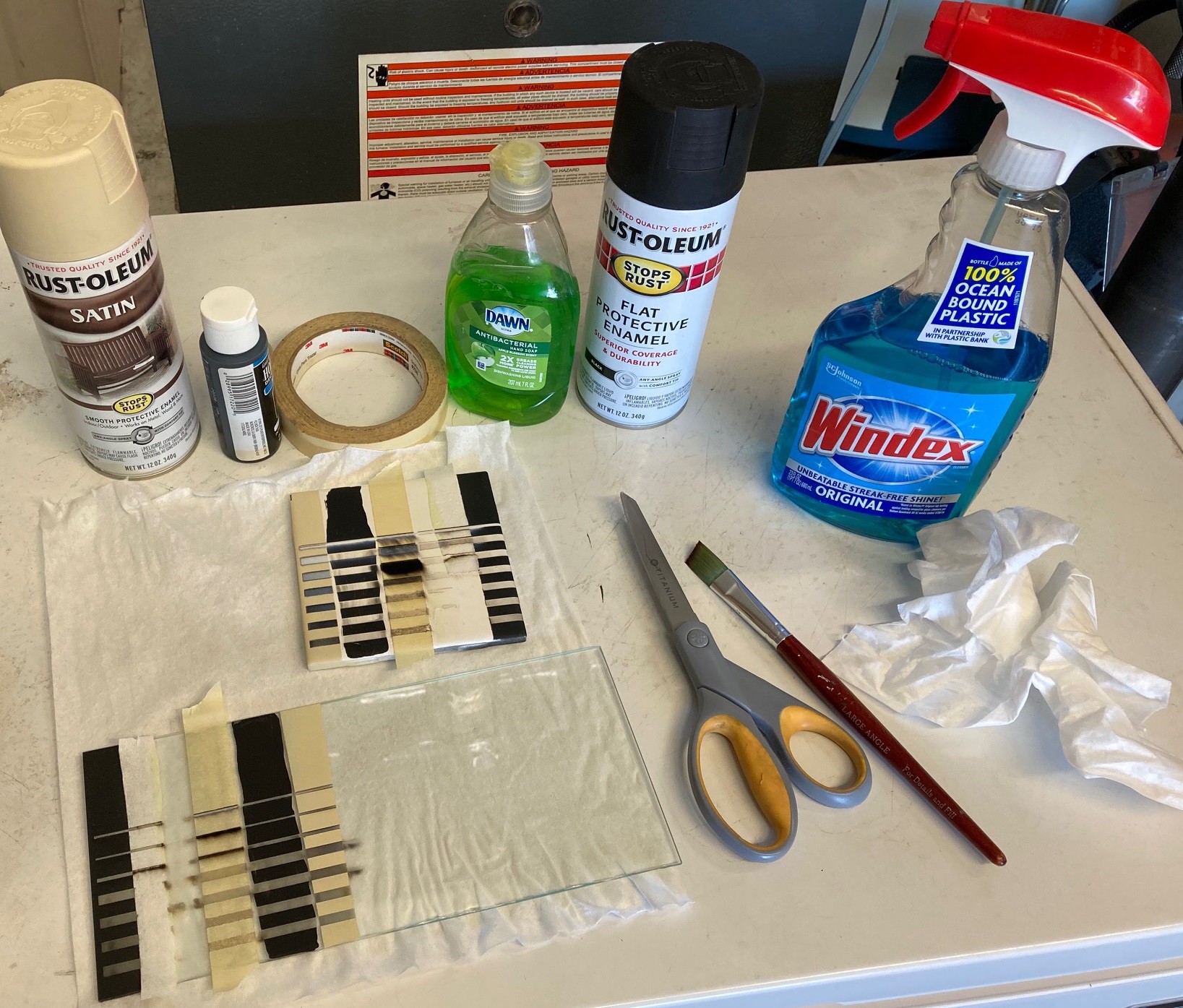
I also had an idea about etching the back side of a piece of glass in a picture frame to make a 3D'ish looking image. To test this out I pulled out a spare white tile, as well as a scrap piece of glass. I had seen several different ideas online, everything from masking tape, soap, a wet paper towel, tempera paints and black and white paint to help aid in the etching process. I prepared each in turn on both materials and ran a series of lines at varying speeds.
![]()
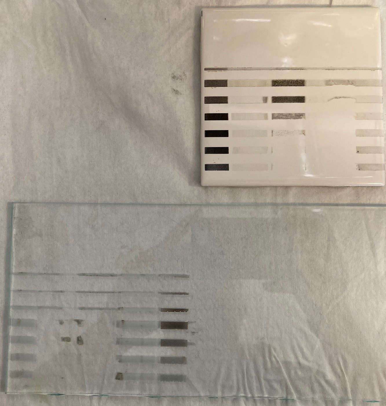
Once you clean things up you can see the white paint worked the best on the white tile. This was not the 'official' paint everyone uses, just what I had laying around. I will try it again with proper paint someday. The wet paper towel was completely useless. It was impossible to keep wet, and it stopped me from using the air assist. The soap was equally useless, I'm not sure what the idea is here, maybe I'm doing it wrong. The tempera paint worked ok, but it is impossible to apply evenly. The black paint etched the glass (and tile) well, but it does not discolor the etching so it is difficult to see. The white paint left a darkened etch that does not come off when you scrub it.
I tried using the white paint to etch a proper image on the glass, but I messed up the settings. The end result was no image at all. I need to run another test, with the right white paint. Another issue is that there was a lot of flash back and accidental etching on the back side of the glass. I'm going to try putting a uniform sheet of paper under the glass to try and minimize this.
Anyway I have low hope of this working well with a picture frame, I may need to explore other ways to burn an image and frame it.
-
LightBurn take 2^42
06/05/2022 at 21:37 • 0 commentsSo recently I got a paid commission. A Facebook acquaintance of my wife's needed a quick bunch of balloons cut out of plywood for a party. It was a rush job that I put together in one day, and I ended up putting a few hours on it as well as using a full sheet of wood so I charged $30. If it was a repeat cut that I could take a few days on I would have charged $20.
Between that job and all my cardboard elephant cutouts I have been pushing the laser extra hard recently. For starters it is 110 F in my garage, and that is making it difficult for the laser to stay cool. I'm only running it at 80% power, but the housing is hot to the touch. I can still hold my finger on it, but it is uncomfortable and probably too high if I want my diode to last a long time.
Another issue is my on going struggle to get Lightburn to work well with my grbl controller. I can't tell you how frustrating this is. Every other sender is happy to work in a virtual coordinate mode as well as an absolute mode with a properly homed system. Lightburn on the other hand is overly picky and that makes this a really frustrating experience.
- First, for some reason, they insist on only using a positive coordinate system, that is that 0,0 is the lower left corner of the machine. You can actually tell it that 0,0 is the upper right corner of the machine, but then they insist on inverting the direction your axis move. That does not even make sense, who sets there machine up backwards? Homing on the upper right corner is the norm for half the machines that lightburn runs on. On top of this, you can read the coordinate system out of the controller, so we should not even need to tell lightburn how the machine is setup.
- Next they insist on having soft workspace limits, even if the machine is not homed (or can not be homed). So you have to input the max coordinates of the machine, but when lightburn starts up 0,0 is set randomly based on how the machine was powered on, making this hard limit totally pointless. Other senders take care of this by leaving the machine in a locked state, and letting you either manually unlock it, jog to 0,0 and reset the coordinates, or by forcing you to home. Lightburns official recommendation is to manually move the laser to 0,0 and restart the machine and lightburn.
- Finally jogging is annoying at best. Often times I turn on the machine and can only jog in one direction. Or even worse the machine will move backwards! That forces me to shut down lightburn and use UGS to jog the machine to a better spot then start lightburn back up again. And with continuous jog mode enabled you can't adjust the z height of the laser, why I don't know.
The recommended solution is to home the machine and mess with the coordinate system to force it into a positive workspace. Previously I had made a macro to do this, but it still trips you up if you forget to home the machine, or if the moon is in retrograde and so on.
This is my 3rd (5th?) attempt to fix this. I reset all of Lightburn settings back to there defaults and made a new macro that not only resets the coordinates, but homes the machine and then moves the laser to 0,0 in preparation of the first cut. Since I have my new laser bed with a fixed edge that is very reliable I can set this up with some precision. I ended up switching the laser to absolute coordinates at the same time. That makes 0,0 be the farthest lower left corner of the machine no matter where I place the part on the lightburn workspace. Hopefully that will reduce instances of the cut start point moving around at random on the machine.
$32=1 ; turn on laser mode
$10=0 ; set coordinates to work position mode (virtual coordinates)
$H ; Home the machine
G10 L2 P1 X-340 Y-433 ; set work offset to -340,-433 or lower left corner
G90 X0 Y0 ; fast move to 0,0 position
Above is my macro, with comments. I'm not sure that lightburn can handle comments, you may need to strip those out if you use this. And be sure to home the machine using UGS and then jogging over to your lower left (safe) edge to get the -x,-y values, don't use mine or you will most likely crash.
This seems to be working ok, now that homing is built into the macro it is more difficult to mess things up. However there are still issues, for example if I move a design off the lower left corner of the workspace even by a fraction of a mm then the whole object won't be cut. Yet Lightburn won't prevent me from moving off the corner, or snap to the corner properly either, and I only get a hint about the problem when I go to engrave, rather than having the object blink or turn red.
Hopefully this helps in the long run, but I find it very frustrating that I have to keep messing with this and there are no aids to help get it going. I don't see how most CNC users manage to get Lightburn to work safely out of the box. Especially when tools like UGS seem to get it right the first time straight out of the box. There doing things in the name of safety, but I never have UGS shoot off in a random direction while Lightburn has crashed into the side of my machine several times for no apparent reason.
-
PaperCraft
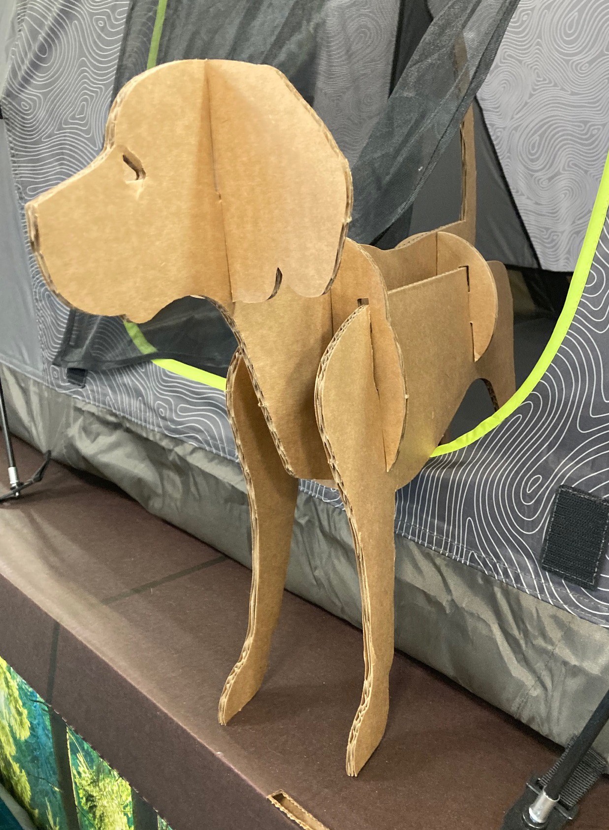
06/05/2022 at 04:55 • 0 commentsMy wife is teaching summer school and they are doing a unit on Thailand. Part of the unit is studying the animals and elephants are at the top of the list. I was strolling through the local pet store and came across the following cardboard cutout being used in a display. Looking at it for a moment, it occurred to me that I could replicate this with my laser cutter and some leftover Amazon packing boxes.
![]()
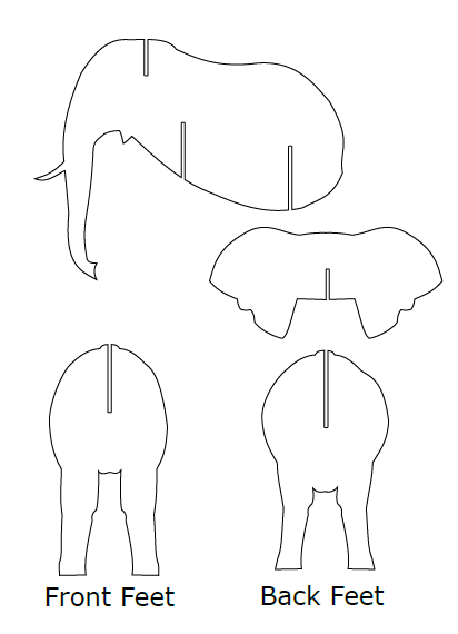
To make this work I first pulled up some profile and head on images of elephants and scaled them to be the same height.
Then I brought them all into Inscape and outlined them by hand with the pencell tool. A little cleanup later and adding in some slots and I ended up with something like this.
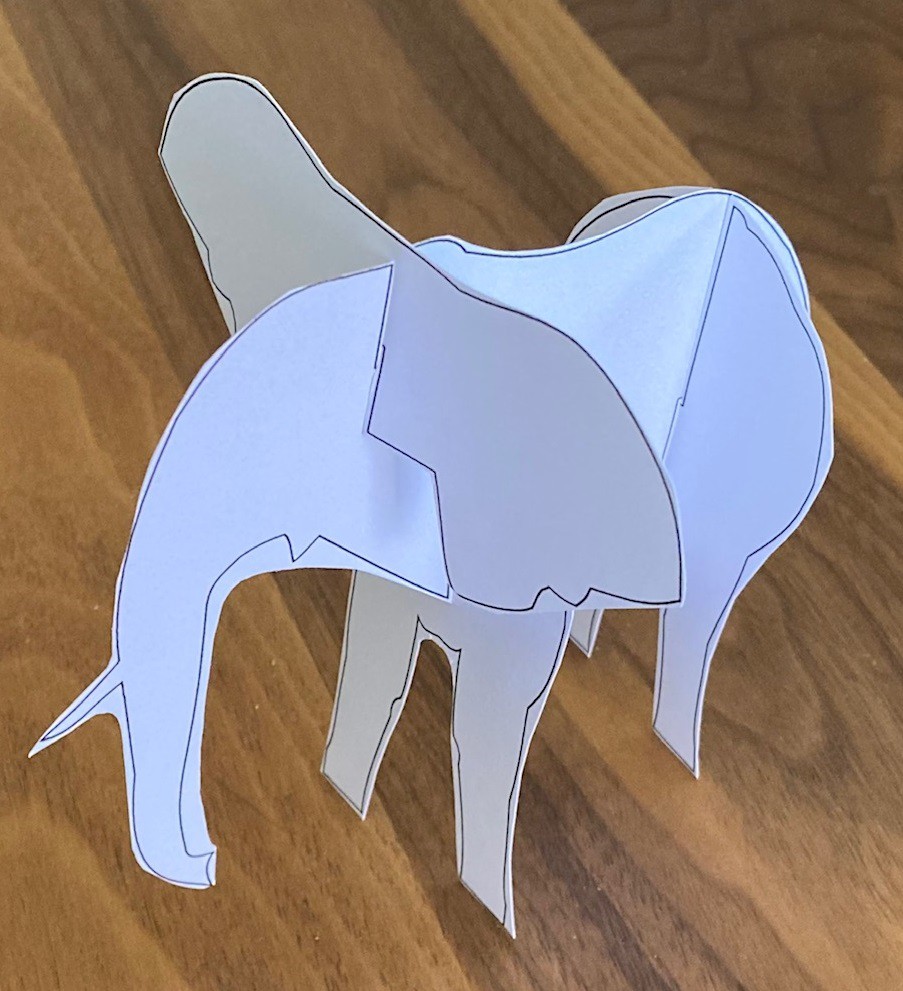
I worked this up as a PDF that is sized to fit on a standard sheet of office paper, as well as a svg that could be imported into light burn. The PDF is designed for students to color and cut out, so I made a test build on cardstock with a very rough cutout and it seems to work well.
![]()
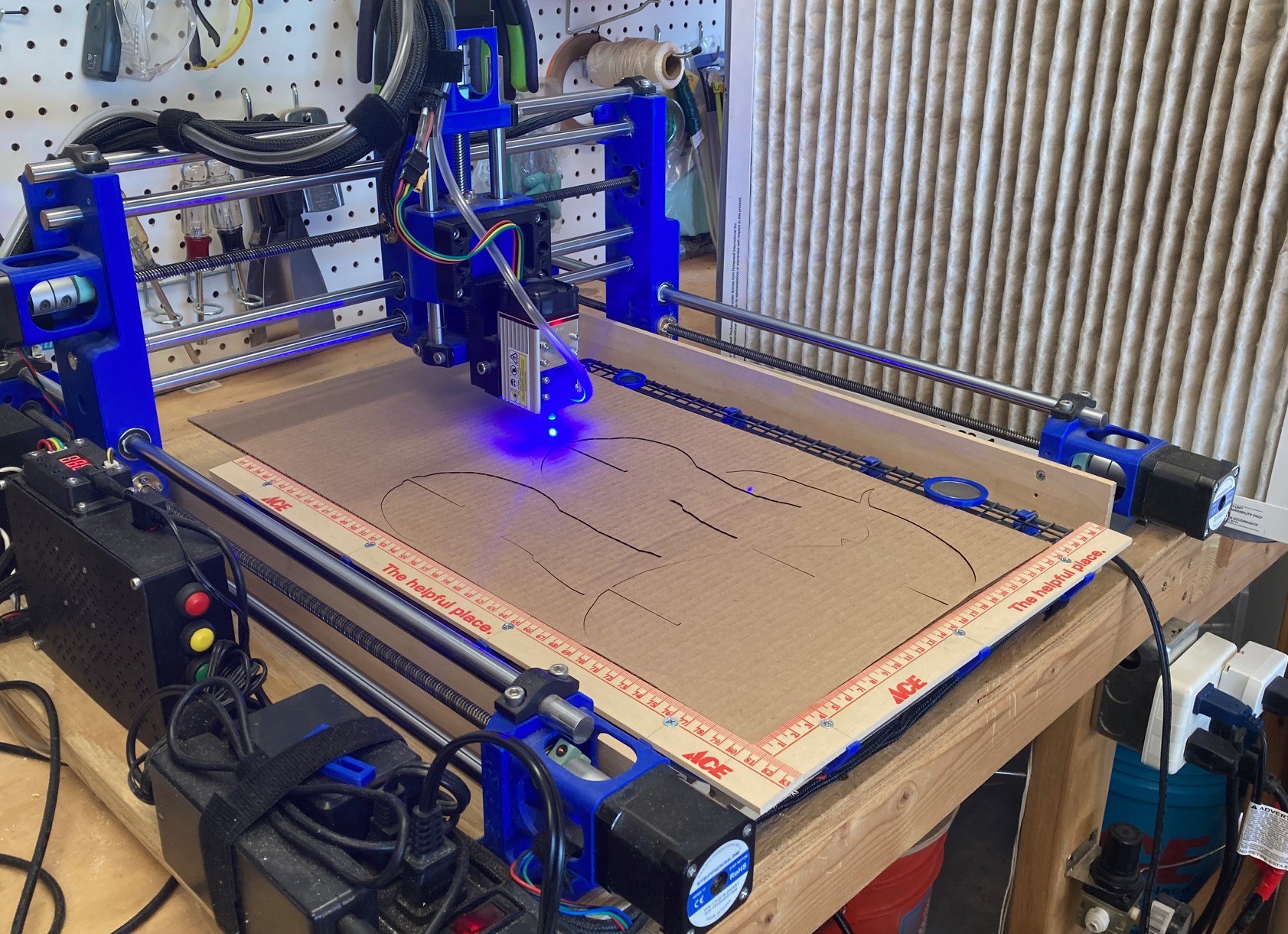
A quick bit of testing on my cnc and I came up with a feed rate of 600 mm/min at 80% power and one pass using my Neje A40640 laser module. I probably could have pushed this a bit faster to save time, but it was not too bad.
![]()
I had collected a pile of Amazon boxes for this project, so I went a bit nuts cutting out elephants. In the end I made 14 or so in two different sizes. The whole project probably took 2 hours from start to finish and it was technically not very difficult. It is a good starter project if you want to make your own cardboard cutouts.
![]()
Here is a link to the pdf file, as well as the svg file if you are interested in cutting out your own elephant. Your free to do anything you want with these, I claim no rights to the files.
-
Cost of Business
05/30/2022 at 06:41 • 0 commentsSo I have been making lots of Pocket Hugs for my wife. She now has lots of happy students with a little reminder that there teacher believes in them. Because of this I'm running out of material and so it is time to look for a new source of wood.
So far I have just picked up a sample pack of Baltic birch from Woodcraft, however I only really need the 1/8" material, and that works out to around $8 a sheet if I keep getting the sample packs. So it is time to try and find a better supplier.
Locally I have a Woodcraft store, a shop called WoodWorkers Source, Home Depot, and a Michaels craft store. In addition I can order wood from Amazon, a place called MakerStock, and of course Glowforge sells there own material.
My machine has a comfortable working volume of around 13"x17" if I want to keep everything on the laser bed. I can find wood that is 12"x12", 12"x20", 12"x30", and larger sizes. I can take a 12"x30" sheet and cut it in two with my circular saw to end up with 12"x15" sheets.
I worked up a spreadsheet with price and size information from every seller I could find (within reason) and worked out a price per cubic foot to better help compare the different sizes together as well. Finally I added a column that compares the percent increase in cost from the cheapest source.
https://docs.google.com/spreadsheets/d/1EW7SMuf_VrciPz5VesTx-LwNsKQrLVT78oHxsT5N9dA/edit?usp=sharing
It should come as no surprise but the Glowforge material is by far the most expensive, coming in at around $13 a square foot, when bought in quantity. Shipping plays a big part in this, it is much cheaper to buy local (or from Amazon) than trying to ship these heavy materials around. Michaels may have better material available in store, but all I could find online was Glowforge material. This is still cheaper than ordering it from Glowforge directly because you skip out on the shipping.
The cheapest source by far is buying a full sheet at WoodWorkers Source and having them cut it down to 12"x30". From there I would need to cut each in half, but it comes out to around $1.80 (plus tax) a square foot. Amazon has some suspect plywood from China that they claim is Baltic birch for $1.90 a square foot, but the reviewers who have tried cutting it with a laser don't seem impressed.
A 12"x12" piece from woodcraft is not a great deal at $5 a piece, but buying a 12"x30" piece and cutting it in half is a much better deal. The best idea is the full sheet from WoodWorkers Source, but sadly they are out of stock. I will probably pick up some pieces from woodcraft as a place holder and give wood workers source a try later when things are back in stock.
-
Taking stock of Particles
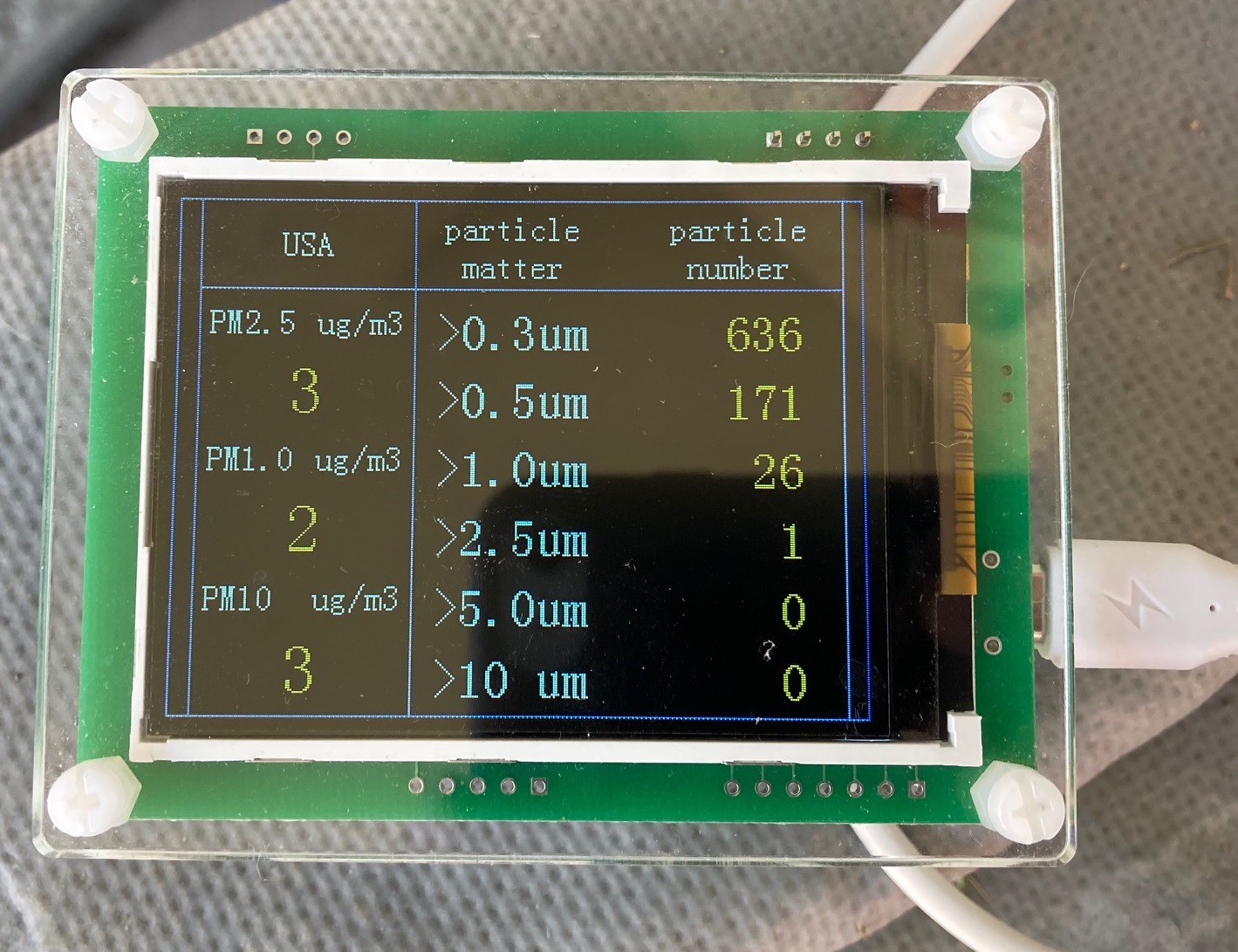
05/28/2022 at 23:50 • 0 commentsSo a while ago I picked up this low cost dust monitor from somewhere. It is based around a Plantower PMS5003 Air Quality Sensor. It never seems to work correctly, that is the PM 2.5 and PM 5 values almost never move above 3, even when I'm cutting with the laser. A while back I ordered a new dust sensor to see if that was the problem, however the new sensor acts the same as the original.
![]()
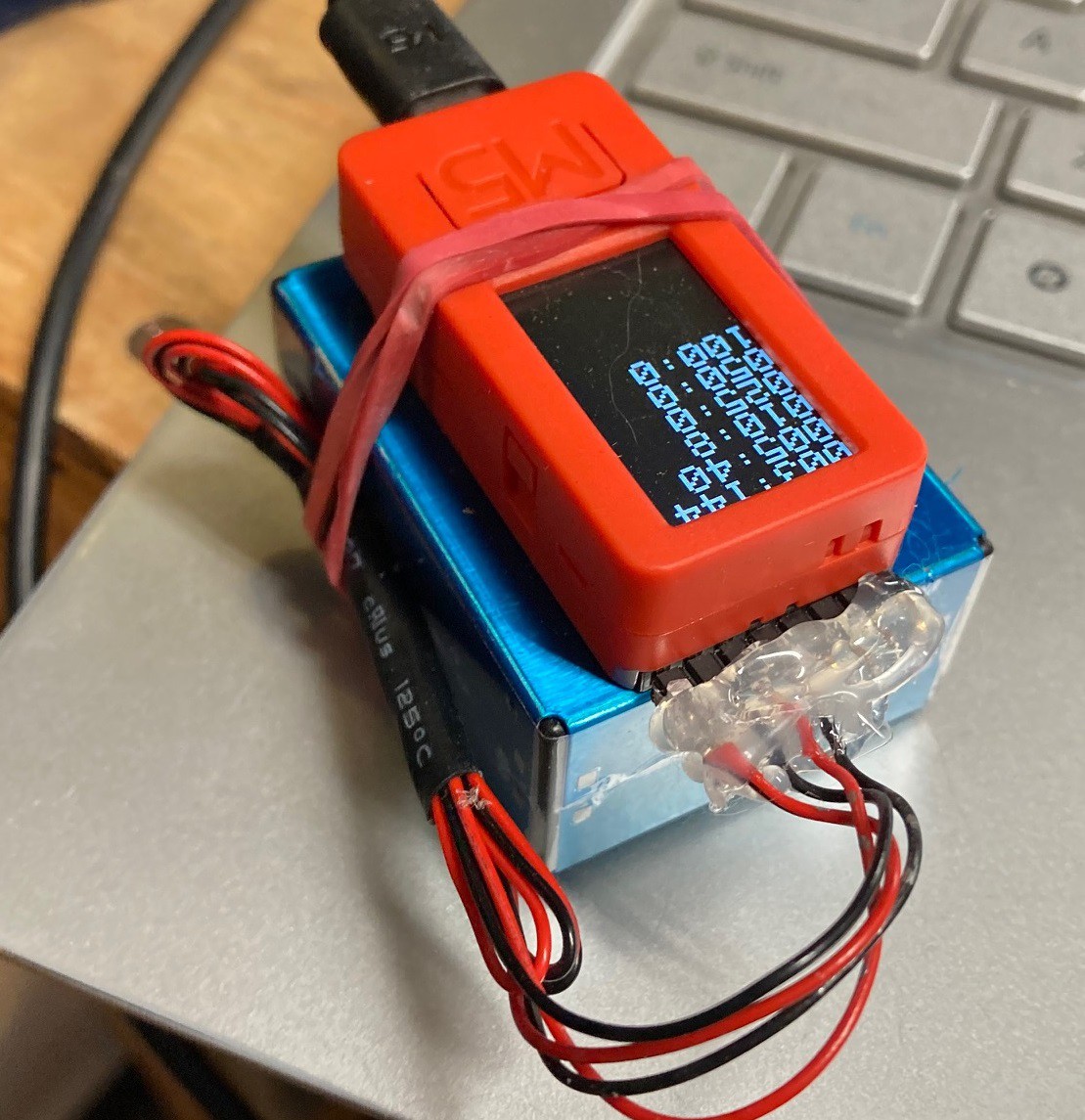
Since I now have two sensors, and it appears they both work equally well (or bad) I decided to wire one up to a M5StickC Plus module and see what I could get out of it. This actually works out really well. The M5StickC is a 3.5v module, but it has a 5v battery so we can supply the needed 5v to run the fan, while still using 3.5v for the logic pins.
![]()
The code is very simple, and minimal. Here it is in its full. This relies on the Adafruit PM25AQI library for the communication. 90% of the code is just moving data from the sensor to the serial port and display, easy peasy.
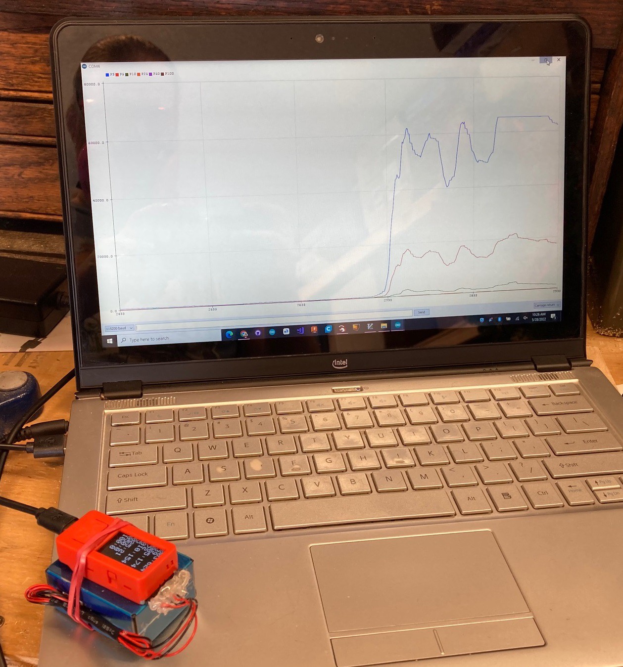
#include <M5StickCPlus.h>
#include <SoftwareSerial.h>
#include "Adafruit_PM25AQI.h"

SoftwareSerial swSerial(25, 26); // in/out
Adafruit_PM25AQI aqi = Adafruit_PM25AQI();
PM25_AQI_Data data;

void setup()
{
  M5.begin();

  M5.Lcd.setTextSize(3);
  M5.Lcd.setRotation(0);

  Serial.begin(115200);
  while (!Serial) delay(10);

  // Wait one second for sensor to boot up
  delay(1000);

  swSerial.begin(9600);

  //aqi.begin_I2C();
  aqi.begin_UART(&swSerial);
}

void loop()
{
  if (swSerial.available() && aqi.read(&data))
  {
#if 0
    Serial.print("PM1:"); Serial.print(data.pm10_standard);
    Serial.print(",PM2_5:"); Serial.print(data.pm25_standard);
    Serial.print(",PM10:"); Serial.print(data.pm100_standard);
    Serial.print(",ePM1:"); Serial.print(data.pm10_env);
    Serial.print(",ePM2_5:"); Serial.print(data.pm25_env);
    Serial.print(",ePM10:"); Serial.print(data.pm100_env);
    Serial.println();

    M5.Lcd.fillScreen(BLACK);
    M5.Lcd.setCursor(0, 0);

    M5.Lcd.print("010:"); M5.Lcd.println(data.pm10_standard);
    M5.Lcd.print("025:"); M5.Lcd.println(data.pm25_standard);
    M5.Lcd.print("100:"); M5.Lcd.println(data.pm100_standard);
    M5.Lcd.print("010:"); M5.Lcd.println(data.pm10_env);
    M5.Lcd.print("025:"); M5.Lcd.println(data.pm25_env);
    M5.Lcd.print("100:"); M5.Lcd.println(data.pm100_env);
#else
    Serial.print("P3:"); Serial.print(data.particles_03um);
    Serial.print(",P5:"); Serial.print(data.particles_05um);
    Serial.print(",P10:"); Serial.print(data.particles_10um);
    Serial.print(",P25:"); Serial.print(data.particles_25um);
    Serial.print(",P50:"); Serial.print(data.particles_50um);
    Serial.print(",P100:"); Serial.print(data.particles_100um);
    Serial.println();

    M5.Lcd.fillScreen(BLACK);
    M5.Lcd.setCursor(0, 0);

    M5.Lcd.print("003:"); M5.Lcd.println(data.particles_03um);
    M5.Lcd.print("005:"); M5.Lcd.println(data.particles_05um);
    M5.Lcd.print("010:"); M5.Lcd.println(data.particles_10um);
    M5.Lcd.print("025:"); M5.Lcd.println(data.particles_25um);
    M5.Lcd.print("050:"); M5.Lcd.println(data.particles_50um);
    M5.Lcd.print("100:"); M5.Lcd.println(data.particles_100um);
#endif
  }
  else
  {
    delay(10);
  }
}
After letting this run while doing some engraving and then cutting I ended up with the following plot. You can't tell from this plot but most of the data on the left was collected when engraving. It produced a signal about 3x stronger than the baseline, but about 20x less strong than when cutting. I never saw the 5 nanometer and 10 nanometer readings go above 1, I suspect this detector is incapable of classifying anything larger than 2.5 nanometers. Also you can see in this graph that the sensor peaks out at 65535, and that was with the sensor being upwind from the laser and not really in the heavy smoke.
![]()
Looking at the raw sensor data, it turns out the PM 2.5 and PM 5 values are in fact fairly useless. They don't have a fractional component so they are in fact only set to 1,2,3... and even at high smoke count the PM levels just don't get very high, it is not very good at letting you know how much smoke is in the air.
The particle counters on the other hand have more potential. They seem very responsive and they break down the particle size into bins ranging from 0.01 to 2.5 um. However I struggled to find much information tying particle size to PM (particle mass). It turns out that PM 2.5 is the measure of the mass of all particles at a size of 2.5 um and smaller. Basically you take each count from each bin and multiply that by the estimation of the average mass of the particles you expect to see in the air to derive the PM 2.5 value. This is basically a wild guess, because you don't know what the weight of the particle is, only its size, and the size and weight are not strongly correlated.
Anyway PM2.5 is almost completely dominated by particles in the 2.5 um diameter, with the smaller and much more common particle sizes not contributing much of anything to the mass of the material. This contributes to the PM2.5 output being so binary since we rarely get any counts of particles in the PM2.5 bins.
Here are some more papers that may help sort this out, if you are curious.
https://cdn-shop.adafruit.com/product-files/3686/plantower-pms5003-manual_v2-3.pdf
https://amt.copernicus.org/articles/14/4617/2021/amt-14-4617-2021.pdf
http://www.energiazero.org/cophenagen/ParticleDistributionDependencyPlantowerPMS5003.pdf
-
Good Vibrations
05/07/2022 at 00:16 • 1 commentAt work I needed to precisely measure the vibration frequencies of a device. I pulled out a M5StickC that I had laying about and wrote some custom code for it. This is a small ESP32 based micro controller with a built in LED display, battery, accelerometer, compass and enough processing power to run a proper FFT in a reasonable amount of time, all in a package the size of your thumb.
![]()
Anyway I needed to measure as high a frequency as I could, but out of the box the accelerometer was only outputting data at around 100 Hz, much too slow for my needs. A little dig through the documentation and I came up with this function to bump the update rate to 1 KHz.
void MPU6886_I2C_Write_NBytes(uint8_t start_Addr, uint8_t number_Bytes, uint8_t *write_Buffer)
{
  Wire1.beginTransmission(MPU6886_ADDRESS);
  Wire1.write(start_Addr);
  Wire1.write(*write_Buffer);
  Wire1.endTransmission();
}

void speedUpSampleRate()
{
  uint8_t regdata;

  // try and boost the i2c update rate, to 400KHz
  Wire1.setClock(400000);

  // up the sample rate
  //regdata = 0x08; // 4 KHz, no filtering
  regdata = 0x00; // 1 KHz, 230 Hz lp filter
  MPU6886_I2C_Write_NBytes(MPU6886_ACCEL_CONFIG2, 1, regdata);

  // turn off sample rate divider
  regdata = 0x00; // no divider
  //regdata = 0x01; // 1 divider
  MPU6886_I2C_Write_NBytes(MPU6886_SMPLRT_DIV, 1, regdata);
}

void setup()
{
  M5.begin();
  M5.MPU6886.Init();
  speedUpSampleRate();
}
I also needed to take the collected data and convert it to the frequency domain via a FFT. I wanted to do this on the device itself, rather than sending it over the serial port before processing. I quickly found the Arduino FFT library, it seems to be what everyone uses. It worked fine out of the box, it was fast and seemed accurate. However it had one problem, the amplitudes that came out of the library were suspect at best. I dug around for a while and found that others had come to the same conclusion. After experimenting with all there ideas I came up with this simplified version of the Arduino FFT library that fixes things so the amplitudes are valid. I spent the better part of a day pushing data through this to verify it is in fact working now.
Note that when you call ComplexToMagnitude the input is the sine()/cosine() pair for each frequency and the output should be the amplitude and phase shift for each frequency. However this code only computes the amplitude and basically trashes the phase shift info. It is a shortcoming that needs to be fixed someday. This is 90% based on the developer branch of the arduinoFFT library, but backported to the main branch without reorganizing the code. Just save it to a arduinoFFT.h file and drop it into the same folder as your .ino file if you want to use it, no need to import it as a library. I stripped out all the legacy calls, and replaced them with a single updateDataSet() call, mostly to stop all the compiler warnings cause by the defines sprinkled around the original code.
These two pieces of code together have me reliably getting frequency data from accelerations between 0 and 500 Hz and with a FFT size up to 4096 bins. This is not your fathers arduino, that is for sure!
Oh, and I used this project from SwitchScience as the base for all my work, but modified it heavily. It is an interesting site and a fun read. You probably need to install google translate in your browser, if you don't read Japanese, it works quite well. I'm not going to publish my full project, I did that on company time, but the above code snippets should be more than enough to get you up to speed, and hopefully it will help someone else who also wants to dig into FFT on an embedded microprocessor in the future.
/* FFT library Copyright (C) 2010 Didier Longueville Copyright (C) 2014 Enrique Condes This program is free software: you can redistribute it and/or modify it under the terms of the GNU General Public License as published by the Free Software Foundation, either version 3 of the License, or (at your option) any later version. This program is distributed in the hope that it will be useful, but WITHOUT ANY WARRANTY; without even the implied warranty of MERCHANTABILITY or FITNESS FOR A PARTICULAR PURPOSE. See the GNU General Public License for more details. You should have received a copy of the GNU General Public License along with this program. If not, see . */ #ifndef arduinoFFT_h /* Prevent loading library twice */ #define arduinoFFT_h #ifdef ARDUINO #if ARDUINO >= 100 #include "Arduino.h" #else #include "WProgram.h" /* This is where the standard Arduino code lies */ #endif #else #include <stdlib.h> #include <stdio.h> #ifdef __AVR__ #include <avr/io.h> #include <avr/pgmspace.h> #endif #include <math.h> #include "defs.h" #include "types.h" #endif #define FFT_LIB_REV 0x14 /* Custom constants */ #define FFT_FORWARD 0x01 #define FFT_REVERSE 0x00 /* Windowing type */ #define FFT_WIN_TYP_RECTANGLE 0x00 /* rectangle (Box car) */ #define FFT_WIN_TYP_HAMMING 0x01 /* hamming */ #define FFT_WIN_TYP_HANN 0x02 /* hann */ #define FFT_WIN_TYP_TRIANGLE 0x03 /* triangle (Bartlett) */ #define FFT_WIN_TYP_NUTTALL 0x04 /* nuttall */ #define FFT_WIN_TYP_BLACKMAN 0x05 /* blackman */ #define FFT_WIN_TYP_BLACKMAN_NUTTALL 0x06 /* blackman nuttall */ #define FFT_WIN_TYP_BLACKMAN_HARRIS 0x07 /* blackman harris*/ #define FFT_WIN_TYP_FLT_TOP 0x08 /* flat top */ #define FFT_WIN_TYP_WELCH 0x09 /* welch */ /*Mathematial constants*/ #ifdef __AVR__ static const float _c1[]PROGMEM = {0.0000000000, 0.7071067812, 0.9238795325, 0.9807852804, 0.9951847267, 0.9987954562, 0.9996988187, 0.9999247018, 0.9999811753, 0.9999952938, 0.9999988235, 0.9999997059, 0.9999999265, 0.9999999816, 0.9999999954, 0.9999999989, 0.9999999997 }; static const float _c2[]PROGMEM = {1.0000000000, 0.7071067812, 0.3826834324, 0.1950903220, 0.0980171403, 0.0490676743, 0.0245412285, 0.0122715383, 0.0061358846, 0.0030679568, 0.0015339802, 0.0007669903, 0.0003834952, 0.0001917476, 0.0000958738, 0.0000479369, 0.0000239684 }; #endif class arduinoFFT { public: arduinoFFT(float *vReal, float *vImag, uint16_t samples, float samplingFrequency, float *windowWeighingFactors = NULL); ~arduinoFFT(void); void updateDataSet(float *vReal, float *vImag, uint16_t samples, float samplingFrequency, float *windowWeighingFactors = NULL); uint8_t Revision(void); void DCRemoval(float *vData, uint16_t samples); void ComplexToMagnitude(); void Compute(uint8_t dir); void DCRemoval(); float MajorPeak(); void MajorPeak(float *f, float *v); void Windowing(uint8_t windowType, uint8_t dir, bool withCompensation = false); float MajorPeakParabola(); private: uint16_t _samples; float _samplingFrequency; float *_vReal; float *_vImag; uint8_t _power; float *_windowWeighingFactors; uint8_t _weighingFactorsFFTWindow; // cache of windowType bool _weighingFactorsWithCompensation; bool _weighingFactorsComputed; constexpr static const float twoPi = 6.28318531f; constexpr static const float fourPi = 12.56637061f; constexpr static const float sixPi = 18.84955593f; static const float _WindowCompensationFactors[10]; uint8_t Exponent(uint16_t value); void Swap(float *x, float *y); void Parabola(float x1, float y1, float x2, float y2, float x3, float y3, float *a, float *b, float *c); }; //--------------- arduinoFFT::arduinoFFT(float *vReal, float *vImag, uint16_t samples, float samplingFrequency, float *windowWeighingFactors) { updateDataSet(vReal, vImag, samples, samplingFrequency, windowWeighingFactors); } arduinoFFT::~arduinoFFT(void) { // Destructor } void arduinoFFT::updateDataSet(float *vReal, float *vImag, uint16_t samples, float samplingFrequency, float *windowWeighingFactors) { this->_vReal = vReal; this->_vImag = vImag; this->_samples = samples; this->_samplingFrequency = samplingFrequency; this->_power = Exponent(samples); this->_windowWeighingFactors = windowWeighingFactors; this->_weighingFactorsWithCompensation = false; this->_weighingFactorsComputed = false; } uint8_t arduinoFFT::Revision(void) { return (FFT_LIB_REV); } void arduinoFFT::Compute(uint8_t dir) { // Computes in-place complex-to-complex FFT / // Reverse bits / uint16_t j = 0; for (uint16_t i = 0; i < (this->_samples - 1); i++) { if (i < j) { Swap(&this->_vReal[i], &this->_vReal[j]); if (dir == FFT_REVERSE) Swap(&this->_vImag[i], &this->_vImag[j]); } uint16_t k = (this->_samples >> 1); while (k <= j) { j -= k; k >>= 1; } j += k; } // Compute the FFT / #ifdef __AVR__ uint8_t index = 0; #endif float c1 = -1.0; float c2 = 0.0; uint16_t l2 = 1; for (uint8_t l = 0; (l < this->_power); l++) { uint16_t l1 = l2; l2 <<= 1; float u1 = 1.0; float u2 = 0.0; for (j = 0; j < l1; j++) { for (uint16_t i = j; i < this->_samples; i += l2) { uint16_t i1 = i + l1; float t1 = u1 * this->_vReal[i1] - u2 * this->_vImag[i1]; float t2 = u1 * this->_vImag[i1] + u2 * this->_vReal[i1]; this->_vReal[i1] = this->_vReal[i] - t1; this->_vImag[i1] = this->_vImag[i] - t2; this->_vReal[i] += t1; this->_vImag[i] += t2; } float z = ((u1 * c1) - (u2 * c2)); u2 = ((u1 * c2) + (u2 * c1)); u1 = z; } #ifdef __AVR__ c2 = pgm_read_float_near(&(_c2[index])); c1 = pgm_read_float_near(&(_c1[index])); index++; #else c2 = sqrt((1.0 - c1) / 2.0); c1 = sqrt((1.0 + c1) / 2.0); #endif if (dir == FFT_FORWARD) { c2 = -c2; } } // Scaling for reverse transform / if (dir != FFT_FORWARD) { for (uint16_t i = 0; i < this->_samples; i++) { this->_vReal[i] /= this->_samples; this->_vImag[i] /= this->_samples; } } } void arduinoFFT::ComplexToMagnitude() { // vM is half the size of vReal and vImag for (uint16_t i = 0; i < this->_samples; i++) { this->_vReal[i] = sqrt(sq(this->_vReal[i]) + sq(this->_vImag[i])) * 2.0 / this->_samples; } } void arduinoFFT::DCRemoval() { // calculate the mean of vData float mean = 0; for (uint16_t i = 0; i < this->_samples; i++) { mean += this->_vReal[i]; } mean /= this->_samples; // Subtract the mean from vData for (uint16_t i = 0; i < this->_samples; i++) { this->_vReal[i] -= mean; } } void arduinoFFT::DCRemoval(float *vData, uint16_t samples) { // calculate the mean of vData float mean = 0; for (uint16_t i = 0; i < samples; i++) { mean += vData[i]; } mean /= samples; // Subtract the mean from vData for (uint16_t i = 0; i < samples; i++) { vData[i] -= mean; } } void arduinoFFT::Windowing(uint8_t windowType, uint8_t dir, bool withCompensation) { // check if values are already pre-computed for the correct window type and compensation if (_windowWeighingFactors && _weighingFactorsComputed && _weighingFactorsFFTWindow == windowType && _weighingFactorsWithCompensation == withCompensation) { // yes. values are precomputed if (dir == FFT_FORWARD) { for (uint_fast16_t i = 0; i < (this->_samples >> 1); i++) { this->_vReal[i] *= _windowWeighingFactors[i]; this->_vReal[this->_samples - (i + 1)] *= _windowWeighingFactors[i]; } } else { for (uint_fast16_t i = 0; i < (this->_samples >> 1); i++) { this->_vReal[i] /= _windowWeighingFactors[i]; this->_vReal[this->_samples - (i + 1)] /= _windowWeighingFactors[i]; } } } else { // no. values need to be pre-computed or applied // Weighing factors are computed once before multiple use of FFT // The weighing function is symmetric; half the weighs are recorded float samplesMinusOne = (float(this->_samples) - 1.0); float compensationFactor = _WindowCompensationFactors[windowType]; for (uint16_t i = 0; i < (this->_samples >> 1); i++) { float indexMinusOne = float(i); float ratio = (indexMinusOne / samplesMinusOne); float weighingFactor = 1.0; // Compute and record weighting factor switch (windowType) { case FFT_WIN_TYP_RECTANGLE: // rectangle (box car) weighingFactor = 1.0; break; case FFT_WIN_TYP_HAMMING: // hamming weighingFactor = 0.54 - (0.46 * cos(twoPi * ratio)); break; case FFT_WIN_TYP_HANN: // hann weighingFactor = 0.54 * (1.0 - cos(twoPi * ratio)); break; case FFT_WIN_TYP_TRIANGLE: // triangle (Bartlett) #if defined(ESP8266) || defined(ESP32) weighingFactor = 1.0 - ((2.0 * fabs(indexMinusOne - (samplesMinusOne / 2.0))) / samplesMinusOne); #else weighingFactor = 1.0 - ((2.0 * abs(indexMinusOne - (samplesMinusOne / 2.0))) / samplesMinusOne); #endif break; case FFT_WIN_TYP_NUTTALL: // nuttall weighingFactor = 0.355768 - (0.487396 * (cos(twoPi * ratio))) + (0.144232 * (cos(fourPi * ratio))) - (0.012604 * (cos(sixPi * ratio))); break; case FFT_WIN_TYP_BLACKMAN: // blackman weighingFactor = 0.42323 - (0.49755 * (cos(twoPi * ratio))) + (0.07922 * (cos(fourPi * ratio))); break; case FFT_WIN_TYP_BLACKMAN_NUTTALL: // blackman nuttall weighingFactor = 0.3635819 - (0.4891775 * (cos(twoPi * ratio))) + (0.1365995 * (cos(fourPi * ratio))) - (0.0106411 * (cos(sixPi * ratio))); break; case FFT_WIN_TYP_BLACKMAN_HARRIS: // blackman harris weighingFactor = 0.35875 - (0.48829 * (cos(twoPi * ratio))) + (0.14128 * (cos(fourPi * ratio))) - (0.01168 * (cos(sixPi * ratio))); break; case FFT_WIN_TYP_FLT_TOP: // flat top weighingFactor = 0.2810639 - (0.5208972 * cos(twoPi * ratio)) + (0.1980399 * cos(fourPi * ratio)); break; case FFT_WIN_TYP_WELCH: // welch weighingFactor = 1.0 - sq((indexMinusOne - samplesMinusOne / 2.0) / (samplesMinusOne / 2.0)); break; } if (withCompensation) { weighingFactor *= compensationFactor; } if (_windowWeighingFactors) { _windowWeighingFactors[i] = weighingFactor; } if (dir == FFT_FORWARD) { this->_vReal[i] *= weighingFactor; this->_vReal[this->_samples - (i + 1)] *= weighingFactor; } else { this->_vReal[i] /= weighingFactor; this->_vReal[this->_samples - (i + 1)] /= weighingFactor; } // mark cached values as pre-computed _weighingFactorsFFTWindow = windowType; _weighingFactorsWithCompensation = withCompensation; _weighingFactorsComputed = true; } } } float arduinoFFT::MajorPeak() { float maxY = 0; uint16_t IndexOfMaxY = 0; //If sampling_frequency = 2 * max_frequency in signal, //value would be stored at position samples/2 for (uint16_t i = 1; i < ((this->_samples >> 1) + 1); i++) { if ((this->_vReal[i - 1] < this->_vReal[i]) && (this->_vReal[i] > this->_vReal[i + 1])) { if (this->_vReal[i] > maxY) { maxY = this->_vReal[i]; IndexOfMaxY = i; } } } float delta = 0.5 * ((this->_vReal[IndexOfMaxY - 1] - this->_vReal[IndexOfMaxY + 1]) / (this->_vReal[IndexOfMaxY - 1] - (2.0 * this->_vReal[IndexOfMaxY]) + this->_vReal[IndexOfMaxY + 1])); float interpolatedX = ((IndexOfMaxY + delta) * this->_samplingFrequency) / (this->_samples - 1); if (IndexOfMaxY == (this->_samples >> 1)) //To improve calculation on edge values interpolatedX = ((IndexOfMaxY + delta) * this->_samplingFrequency) / (this->_samples); // returned value: interpolated frequency peak apex return (interpolatedX); } void arduinoFFT::MajorPeak(float *f, float *v) { float maxY = 0; uint16_t IndexOfMaxY = 0; //If sampling_frequency = 2 * max_frequency in signal, //value would be stored at position samples/2 for (uint16_t i = 1; i < ((this->_samples >> 1) + 1); i++) { if ((this->_vReal[i - 1] < this->_vReal[i]) && (this->_vReal[i] > this->_vReal[i + 1])) { if (this->_vReal[i] > maxY) { maxY = this->_vReal[i]; IndexOfMaxY = i; } } } float delta = 0.5 * ((this->_vReal[IndexOfMaxY - 1] - this->_vReal[IndexOfMaxY + 1]) / (this->_vReal[IndexOfMaxY - 1] - (2.0 * this->_vReal[IndexOfMaxY]) + this->_vReal[IndexOfMaxY + 1])); float interpolatedX = ((IndexOfMaxY + delta) * this->_samplingFrequency) / (this->_samples - 1); if (IndexOfMaxY == (this->_samples >> 1)) //To improve calculation on edge values interpolatedX = ((IndexOfMaxY + delta) * this->_samplingFrequency) / (this->_samples); // returned value: interpolated frequency peak apex *f = interpolatedX; #if defined(ESP8266) || defined(ESP32) *v = fabs(this->_vReal[IndexOfMaxY - 1] - (2.0 * this->_vReal[IndexOfMaxY]) + this->_vReal[IndexOfMaxY + 1]); #else *v = abs(this->_vReal[IndexOfMaxY - 1] - (2.0 * this->_vReal[IndexOfMaxY]) + this->_vReal[IndexOfMaxY + 1]); #endif } float arduinoFFT::MajorPeakParabola() { float maxY = 0; uint16_t IndexOfMaxY = 0; //If sampling_frequency = 2 * max_frequency in signal, //value would be stored at position samples/2 for (uint16_t i = 1; i < ((this->_samples >> 1) + 1); i++) { if ((this->_vReal[i - 1] < this->_vReal[i]) && (this->_vReal[i] > this->_vReal[i + 1])) { if (this->_vReal[i] > maxY) { maxY = this->_vReal[i]; IndexOfMaxY = i; } } } float freq = 0; if ( IndexOfMaxY > 0 ) { // Assume the three points to be on a parabola float a, b, c; Parabola(IndexOfMaxY - 1, this->_vReal[IndexOfMaxY - 1], IndexOfMaxY, this->_vReal[IndexOfMaxY], IndexOfMaxY + 1, this->_vReal[IndexOfMaxY + 1], &a, &b, &c); // Peak is at the middle of the parabola float x = -b / (2 * a); // And magnitude is at the extrema of the parabola if you want It... // float y = a*x*x+b*x+c; // Convert to frequency freq = (x * this->_samplingFrequency) / (this->_samples); } return freq; } void arduinoFFT::Parabola(float x1, float y1, float x2, float y2, float x3, float y3, float *a, float *b, float *c) { float reversed_denom = 1 / ((x1 - x2) * (x1 - x3) * (x2 - x3)); *a = (x3 * (y2 - y1) + x2 * (y1 - y3) + x1 * (y3 - y2)) * reversed_denom; *b = (x3 * x3 * (y1 - y2) + x2 * x2 * (y3 - y1) + x1 * x1 * (y2 - y3)) * reversed_denom; *c = (x2 * x3 * (x2 - x3) * y1 + x3 * x1 * (x3 - x1) * y2 + x1 * x2 * (x1 - x2) * y3) * reversed_denom; } uint8_t arduinoFFT::Exponent(uint16_t value) { // Calculates the base 2 logarithm of a value uint8_t result = 0; while (((value >> result) & 1) != 1) result++; return (result); } // Private functions void arduinoFFT::Swap(float *x, float *y) { float temp = *x; *x = *y; *y = temp; } const float arduinoFFT::_WindowCompensationFactors[10] = { 1.0000000000 * 2.0, // rectangle (Box car) 1.8549343278 * 2.0, // hamming 1.8554726898 * 2.0, // hann 2.0039186079 * 2.0, // triangle (Bartlett) 2.8163172034 * 2.0, // nuttall 2.3673474360 * 2.0, // blackman 2.7557840395 * 2.0, // blackman nuttall 2.7929062517 * 2.0, // blackman harris 3.5659039231 * 2.0, // flat top 1.5029392863 * 2.0 // welch }; #endif -
Dust in the wind
04/29/2022 at 04:41 • 0 commentsLiving in the desert we are constantly struggling with dust and dirt. The air is so dry that the dust floats uninterrupted for days. Plus we have these amazing seasonal dust storms comically called haboobs that seem to blanket everything in dust.
The dust has finally sent me around the bend and so I brought my home made air filter into the house to see what it could do to help cut things down. This is a Lasko 20" B20200 box fan from Walmart combined with a 20"x20"x1" MERV13 furnace filter.
I had been eying getting a more expensive box fan to see if the extra power (CFM) does anything to improve the filter performance. So I picked up a Lasko 20" Power Plus B20540 box fan from Home Depot and an identical furnace filter to my original one. Not only did I want to see if the better fan was a better performer, but I also wanted to see if multiple air filters in multiple rooms made a difference. My thought is that each filter can only clear so much volume of air around themselves, and so you would need several thorough the house in order to be effective.
The ultimate goal was to pick up a real air filter for the house, or at least determine if a real filter was worth the price or offered any improvement in performance. I spent some time looking around and settled on the BlueAir 311 air filter as a likely candidate. It is sized right for a medium sized room, the price is not bad, and it looks nice compared to the usual fair. I'm also really taken with the idea of the filters having no frame so being easily collapsed during shipping. We don't put enough thought into minimizing waist, this seems like a very good design in my mind.
![]()
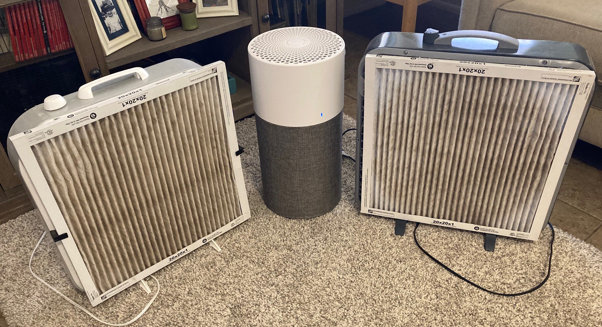
So after running my two home made fans for a few weeks with fresh filters on them, I noticed they were starting to get dirty. With limited evidence that they work I decided to pull the trigger on the BlueAir 311 and started to compare the three filters together.
As an aside, the box fan on the left has a paper baffle on the edges to improve air flow, while the box fan on the right does not. You can see the benefit of the baffles by looking at the corners of the filters, the one on the left has more dirt in the corner while the one on the right is very clean because of air flowing backwards through the filter. The overall surface area here is small, it is not a huge improvement, but I suspect it also improves how linear the air flow is, reducing turbulence and that in turn makes it more efficient as well.
I took some time to measure out each filter. The frontal area of the 20x20x1" filter is 2,030 cm^2, and the frontal area of the BlueAir filter is 2,620 cm^2. That is just the area the filter physically takes up, each filter material is folded into the filter itself and has a larger surface area. The 20" filter has one pleat every 20 mm, while the BlueAir has close to 7 pleats per 20 mm. Multiplying that out the surface area of the filter material is 4,050 cm^2 for the 20" filter and 17,530 cm^2 for the BlueAir filter. Basically the BlueAir has about 4x more surface area, making it have 4x less air resistance, assuming the filter material was identical.
![]()
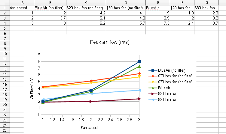
Using my $8 anemometer I measured the peak wind speed of each fan with and without the filter installed at all three speeds. Keep in mind that for $8 this does not use real bearings on the impeller, just cast plastic bearings. I get a different reading at different orientations of the device. I have tried to orient everything the same, but these numbers should be treated as suspect or at least just approximations. Also peak air flow is not as interesting as taking a profile of flow across the whole filter and calculate CFM, but that is a lot more work, so you get this.
Looking at these numbers you can see that the box fans really struggle to push air through a MERV13 filter, they are loosing 2x or more of the air flow through the filter. It would be interesting to try using more than one filter in a wedge or box configuration to see if we can improve the flow. That is an experiment for another day, and one that should probably stay in the garage as well.
The BlueAir filter has almost no air loss with and without the filter in place, it is an extremely efficient design. At low speed it is moving about the same amount of air as the box fan (assuming air speed correlates with CFM, which it probably does not). It is also clear that there needs to be another speed between medium and high for this filter, the air flow doubles between medium and high.
![]()
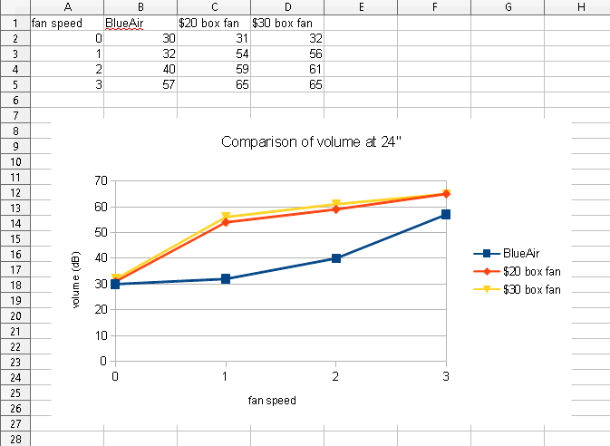
Next I pulled out my dB meter and measured the noise volume of each fan at 24" from the motor and at a 45 degree angle from the center of air flow (to avoid any wind noise). The background noise in the room was around 30 dB for these measurements. The box fans are quite loud even on the lowest speed, easily being louder than the BlueAir on its highest 'turbo' setting. The BlueAir is basically inaudible on low, and you can barely tell it is on at its middle speed. The sound is loud but not horrible on high, much less annoying than either of the box fans.
The cost of the furnace filters is lower than the BlueAir filter. The BlueAir filter is around $40, $34 if you buy it in a subscription. While the furnace filter is around $20, $10 if you buy it in quantity. However in theory with the BlueAir having 4x the surface area it should, in theory, last 4x longer as well so these are more or less equivalent numbers. The BlueAir also has a carbon filter embedded in it, one that does not restrict the flow like the carbon filter glued to a furnace filtercarbon filter glued to a furnace filter that I tried previously.
The BlueAir unit I got is the newer one with a built in particle counter that can automatically ramp up the speed of the fan based on how dirty the air is. This sounds like a good call, but in practice it hardly ever moves off of its lowest setting. I took an incense stick and burned it in the room for a while and the fan never speed up, I had to put the stick right next to the inlet of the particle filter to trigger it. I also set the filter next to my very dusty blinds while dusting them and again it never picked up on the dust, not until I smacked my duster against the particle counter at least.
This is a nice idea in theory but it is flawed. The sensor has its own internal fan and it is trying to draw air in independent of the fan on the air filter. But that makes it compete with the air filter fan. It basically sits in a vacuum between the inlet and outlet of the filter. It would be better if incoming air somehow flowed past the sensor, although I can't see a reasonable way to make that happen. Also the fan itself is very slow to react to a disturbance, it may kick off if you have smoke hanging in the air but if you walk into the house and let in some dirty air it won't be able to detect it in time to remove the dust before it settles out. I ended up leaving the unit on medium permanently, it would be nice if the unit could still kick into high if it detected dust, but basically this is more gimmick than feature. Fortunately it was not an expensive upgrade.
Looking at all the above numbers it is clear that the BlueAir is the better air filter. It moves more air (at least moves it faster), is quieter, and in theory the filter will last a lot longer and can scrub out some organics from the air as well. It also looks much nicer, a selling point if your going to use it in your house. However it also cost $200 (w/filter) rather than $40 for the box fan (w/filter). That is 5x more, is it 5x better? I think it was worth the investment, but it is a bit of a tough sell. I don't understand why air filters are so expensive, they are way overpriced for what they provide for sure. This should cost less than $100 and the filters should be $20 apiece.
It remains to be seen if an air filter does anything to the dust in my house. The filters are collecting dirt for sure, but so does the filter on my furnace. The real question is do we see a reduction in dust in the house. I spent some time thoroughly dusting the house and hope to monitor it over time, but that is hardly a scientific approach. For now I will take it on faith that it is in fact helping, and hope to see some evidence in the future.
---
Matthias over at Woodgears.ca has recently done a more in-depth analysis of his air filters. He is using a particle counter and some smoke evenly spread around the room to more directly measure there ability to remove particles from the air. I'm hoping to resurrect my particle sensor, we will see if I can.
-
Small details
04/29/2022 at 04:05 • 0 comments![]()
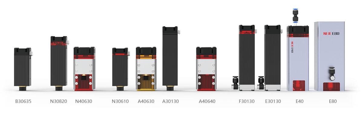
Neje is teasing out a picture about two new modules they are releasing. One is a dual diode E40 module that is basically the same as my A40640 but with a built in air assist and possibly better cooling. The other is a E80 quad diode module that should be twice as powerful as the A40640 module. Both appear to be direct competitors to the new Atomstack modules of the same power.
On an aside, Neje has too many modules, they really need to standardize on one form factor and probably should phase out there weaker modules as well.
![]()
The dust monitor I picked up a while back worked well for a week or two but soon stopped being able to measure any but the strongest levels of dust. I decided to order a new module from AlliExpress, thinking it was the most likely the part that failed. I just got the new module in the mail today and it looked like this! Fortunately the module inside appears to be just fine, although I don't know how it survived. I will try to put it in this weekend and see if it works.
---
I stumbled onto the term mill/turn to indicate a mill with a rotary axis attached to it. This may help in trying to dig up new tools, sometimes knowing the right terms helps.
---
I found an older copy of CNC Wrapper posted by the original author on a forum. The new version has been taken down but now we can experiment with the older version.
https://forum.vectric.com/viewtopic.php?f=2&t=2920&sid=4443ef3bcccbc036b279d7029093b74c
https://forum.vectric.com//viewtopic.php?f=35&t=6449
---
I have been running some experiments on air filters, I will try to get a writeup done in a few days.
-
Round and Round
04/24/2022 at 03:15 • 0 commentsI have circled back to the rotary axis again. I wrote a small utility that can parse gcode and apply a transform to it. I made a bat shaped profile and generated a regular cut for it.
![]()
Then transforming the Y axis to A and applying a rescale of the A axis and adding an offset to the X axis I ended up with this twisted mess. It is hard to see here but it is a real jumble that vaguely looks like a splinched bat.
![]()
Looking at the end of the cut you can see that it is not actually rotating around the axis properly.
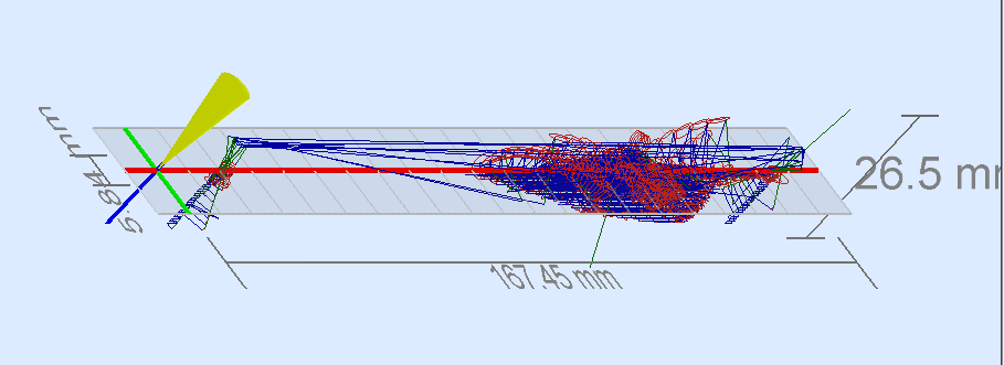
I was wondering if the problem is my code or the viewer so I wrote some simple gcode by hand and loaded it into two different viewers that claim to handle rotary axis. That is UGS and NC Viewer.
![]()
I made a file that draws a series of longs along the X axis then rotates the A axis in small steps. That loads up fine and looks great.
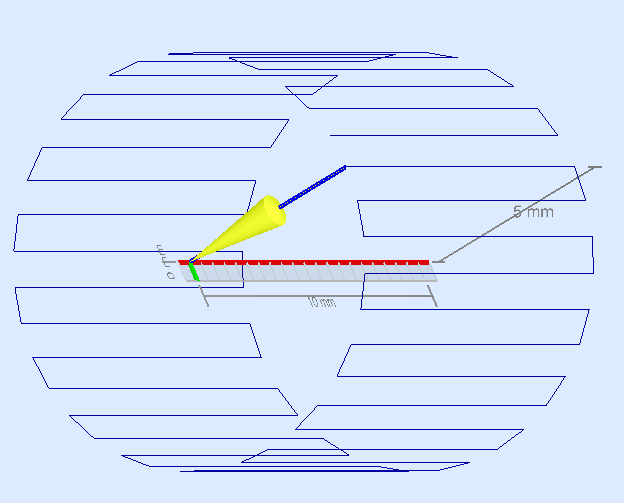
![]()
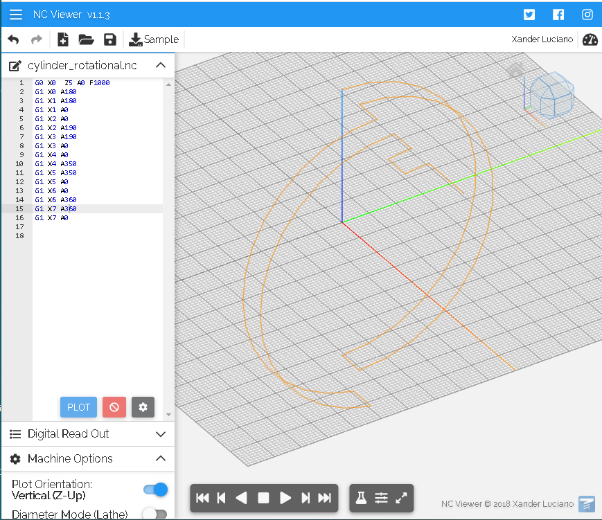
Then I wrote a new file that flips this around, rotating the A axis by 360 degrees then moving the X axis over 1 mm and rotating back to 0. You can see this renders nothing but a straight line.
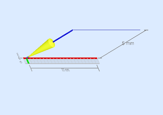
![]()
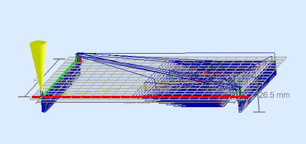
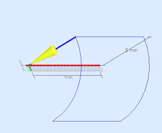
That made me suspect that rotations were not being rendered properly, so I wrote this simpler file that rotates 90 degrees, moves over 10 mm and then rotates back 90 degrees. You can see the renderer is drawing a straight line rather than a curve.
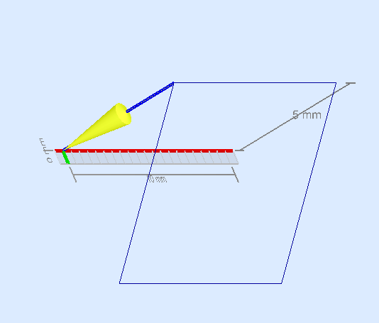
![]()
Finally I modified the last file by rotating in steps of 10 degrees rather than the full 90 degrees in one move. This time it renders properly. Clearly the viewer is rotating the points around the rotary axis properly, however it is not taking the movement of the rotary axis into account when drawing the lines.
You can download the example files from this link if you are curious to look them over.
There is another issue with the viewers. They all assume the origin is set to the center of the rotary axis. This is one way you could deal with this, possibly the best way to deal with this, but it is certainly feasible that the origin is set at the surface of the material.
---
NC Viewer works a bit better than UGS, it works correctly for any small angle rotation from 0-180 degrees, but incorrectly inverts the rotation for anything over 180 degrees.
-
Try, try again...
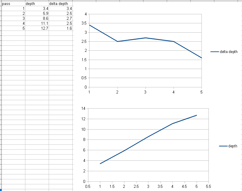
04/17/2022 at 06:02 • 0 comments![]()
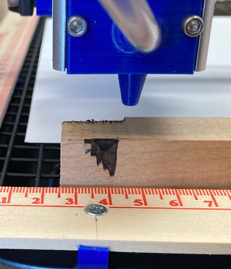
I had an idea to modify my previous multipass test to see if we could get a sense of the maximum depth you can cut when taking multiple passes on a piece. Previously I had cut part of a line at 100% power in one pass, the next at 50% power in 2 passes, and so on. This time I left the power unchanged and just increased the number of passes. In this case I settled on 200 mm/min, 40% power, and a 0.25 mm stepover using my NEJE A40640 laser module cutting into a 19mm thick piece of basswood.
![]()
After letting it run for 12 passes and cleaning up the edge a bit we get the cut above. You can see there is a thinning of the cut with depth. I think this is highly dependent on the density of the wood, with the laser taking the path of least resistance rather than always cutting straight down as you would expect.
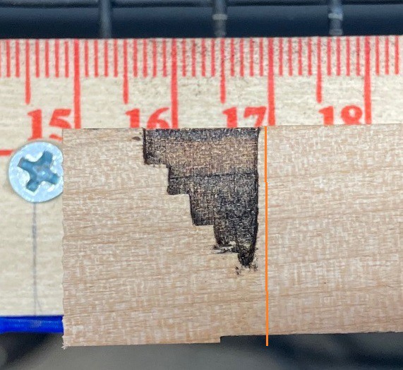
![]()
It is difficult to measure the last cut reliably since it has gotten quite thin. I suspect if I re-ran the same test with 10 passes we would see that depth cutting as well as the ones above it, with the extra space provided by the additional passes.
Anyway you can see from the rough measurements above that the change in depth is fairly linear although we steadily loose a bit of depth with each pass. I had run this same test at 80% power and 150 mm/min but it was burning completely through the wood in only 3 or so passes. This laser is quite capable of cutting soft woods like basswood. I need to get out some thicker Baltic birch plywood and see how well it performs with that.
MultiBot CNC v2
A low cost 3D printed CNC that can be built with minimal tools yet is capable of great things.