David Tucker
-
Stay Focused!
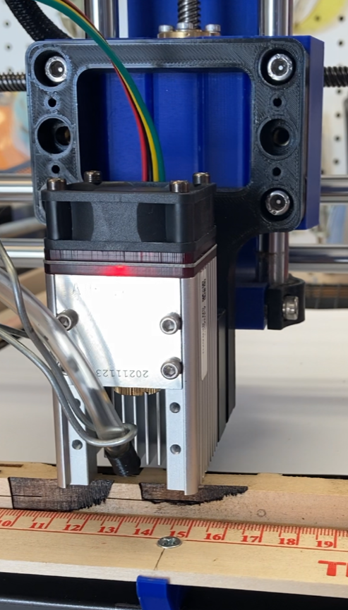
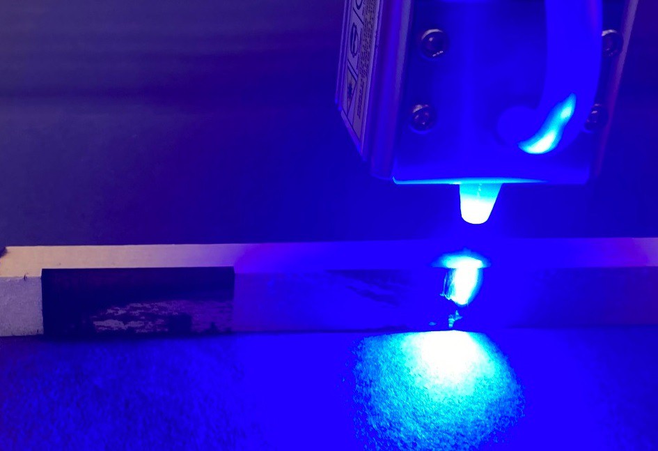
04/10/2022 at 23:43 • 0 commentsSo after my last test I wanted to revisit the idea of how spot size affects the cut depth. I can't think of a reliable way to measure spot size, let alone adjust it with any reliability. However I can raise and lower the laser head while cutting to take it out of focus without actually knowing the spot size. That should give me some sense of what is going on. I had tried this previously but it was a failure. The air assist I was using is attached to the laser head so it moved up and down with the head and affected the cut depth. I also had tried turning off the air assist but that just resulted in a lot of burn damage.
![]()
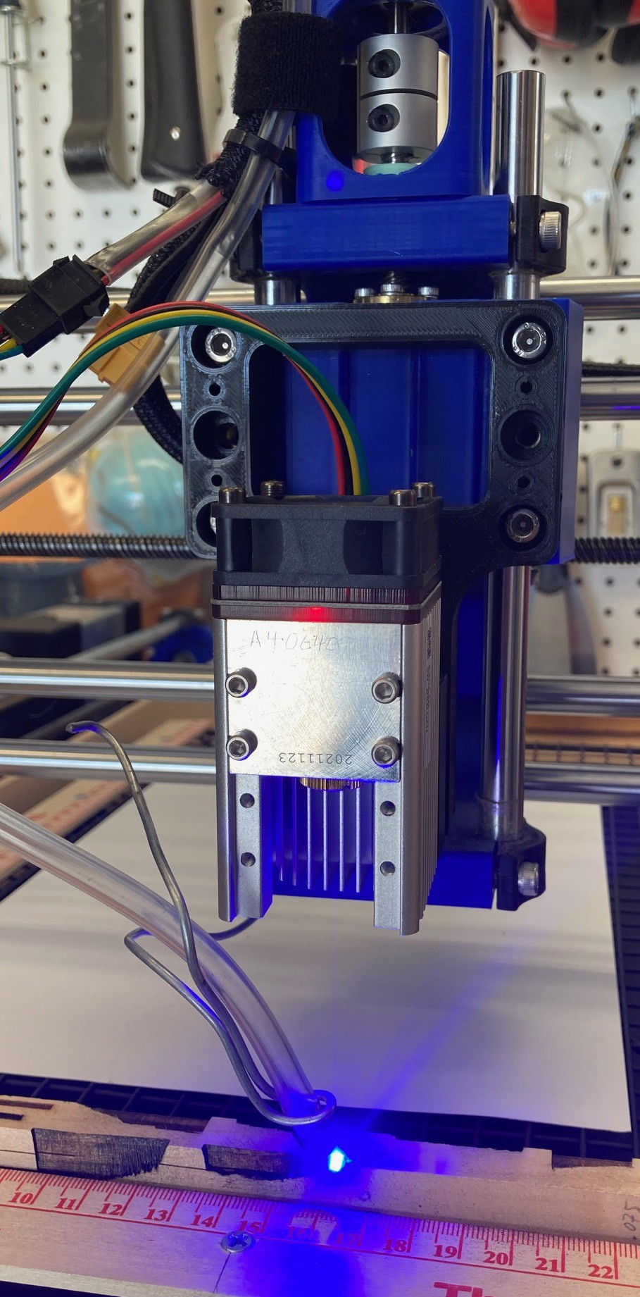
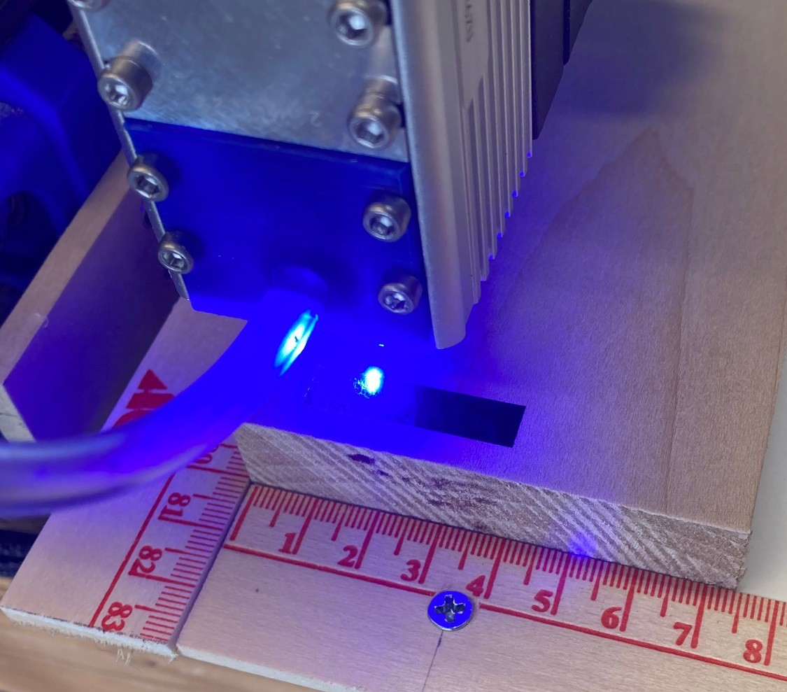
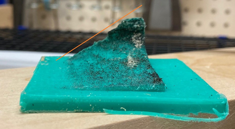
This time I removed my existing nozzle and used a wire attached to the Y carriage to keep the air focused at the cut. This is not ideal, it was sitting at a fairly steep angle, but it seems to have worked. I positioned the laser head as close to the work as I could, then ran a 30 mm long line while raising the head up 75 mm. The line was run at 200 mm/min at 40% power in a 12 mm deep piece of basswood with my NEJE A40640 laser module.
![]()
It is difficult to capture with a photo, but this is really far out of focus at the end of travel.
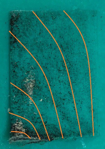
![]()
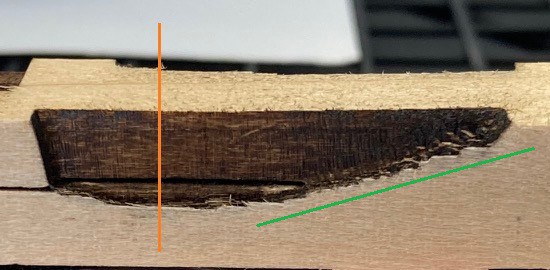
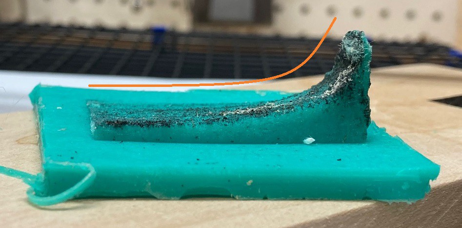
I need to repeat this with some more carful measurements but I think I have marked the position in orange where the laser would just be focusing on the surface of the material. You can see that is also roughly the point where we get the deepest cut. This plays well with my previous experiments that seem to show the laser cuts deepest when focused at the surface, and not several mm below the surface as some manufacturers recommend.
The green line shows that there appears to be a linear relationship between focus height and depth. I would need to do some math to see how height affects spot size. I suspect the tapering off near the orange line has more to do with the waist of the laser resulting in basically no change in spot size across that whole range of focus.
Anyway this is not enough data to really tell if depth = 1/spotSize or not, but it is an interesting first pass at the question. The most interesting to me is how broad of a range of focus you can use and still get a reasonable depth of cut.
---
I put up another project to summarize all my depth of cut experiments into one single post.
-
Deep thoughts
04/09/2022 at 18:45 • 0 commentsI wanted to finish up my investigation into speed vs power and how it relates to cut depth. Previously I worked out the relationship depth = (power * passes) / (speed * spot_size). And I was able to demonstrate that depth increases linearly with power, and decreases logarithmically with speed. Next I found that there is (approximately) a linear relationship between power and passes.
The next part of the equation that I have not covered is the relationship between speed and power. The theory is that if you increase speed you can increase power at a fixed rate to get the same depth of cut.
![]()
After a bit of experimentation to dial it in I came up with the equation speed (mm/min) = power (%) * 700. Varying power from 0.10 to 0.80 (10% to 80%) at speeds from 70 mm/min to 560 mm/min produced the above cut that shows there is in fact a linear relationship between speed and power over at least most of the range. This was done with my NEJE A40640 laser module. The scaling factor would be different for a different power laser.
It is hard to visualize what is going on in the above image but the laser was accelerating from 70 mm/min to 560 mm/min as it traveled left to right, while the laser power was increasing from 10% to 80 % over the same range. Both were increasing at a linear rate. There is a small increase in depth of cut from 10% power to 30% power, that could just be caused by my scale factor being a bit low. It is quite possible that using 800 could have straightened things out, but I ran out of steam after having run quite a few other test cuts previously.
The only big thing left to investigate is how spot size effects depth of cut. However I don't know that I'm well equipped to study that, or at least I can't think of a good way to measure spot size with enough reliability at this time. Maybe I could try running a ramp test on a piece of anodized aluminum and get reliable measure of spot size from that. However in my past experiments with this, the spot size did not seem to change much over the range I could run the ramp over.
---
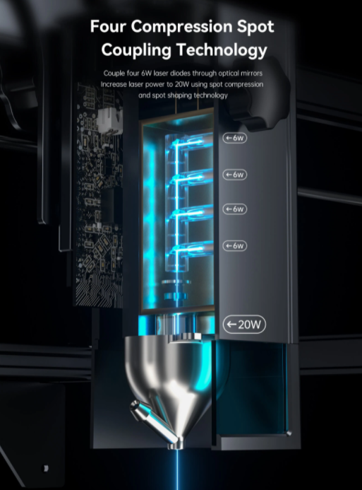
Atomstack has announced a new X20 Pro laser cutter that has 4 5w diodes stacked up in it. That would make it 2x more powerful than my NEJE A40640 module. It also cost a bit more at $1,000 for a smallish 400x400 mm machine with built in air assist. There claiming they can cut 12 mm deep in one pass and can even cut thin sheet metals. I have a feeling they are not wrong on all of that my module is impressive all by itself, if it was 2x stronger it would probably bee too powerful for my machine. that is when engraving at least I would be unable to run fast enough to keep up. There machine is rated at a max speed of 12,000 mm/min or 200 mm/sec. That is in line with the speed range of a CO2 laser.
I had thought that 2 diodes was all you could stack up in a laser, and still have the beams running right on top of each other. This is because my module uses a neat trick where you use a polarized mirror to make the mirror transparent when the laser is oriented in one direction and reflective when oriented in the other so that one laser can pass through the mirror and the other is reflected and combined. This works because part of what makes a laser a laser is that the output is polarized, that is all the light waves are oriented in the same direction and orientation. However it turns out there are in fact other methods of combining lasers, they are just not as simple or as inexpensive.
They also offer a honeycomb bed, although it is a bit undersized for this machine, a rail extension kit, a rotary kit, and even a full metal enclosure. However if you went all in you would be dropping $1,600 on a machine that is probably underpowered compared to a glow forge or 50w CO2 machine. The only real advantage here is that you can drop the water cooler for a much simpler setup, maintenance wise. However I do expect this to come down in price over time and expect to start seeing fully enclosed dual and quad diode laser modules under $1,000 in the next 4-5 years. Considering a glowforge starts at $4,000 having a quad diode enclosed for $1,000 would be very competitive.
-
Pass you by
04/02/2022 at 23:48 • 0 commentsPreviously I have theorized that the equation below holds true.
![]()
I have spent some time exploring the idea that depth is proportional to power, and depth is inversely proportional to velocity. However I have not tried to prove that there is in fact a relationship between power and passes, or power and velocity.
In theory if we hold velocity constant than a cut at a power of 4 and pass of 1 should result in the same depth as a cut with a power of 1 and a pass count of 4. To prove this I wrote a program that runs over the same line 4 times, with one segment of the line being cut at full power in one pass, another at 1/2 power in two passes, 1/3 power in 3 passes and 1/4 power in 4 passes.
![]()
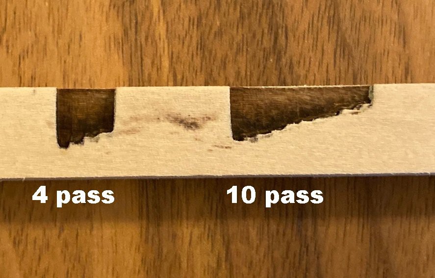
This actually can scale to any number of passes, the cut on the right uses 10 passes and seems to look roughly the same as the 4 pass cut on the left. In the above image the full power single pass is on the left while the lowest power, highest number of passes is on the right.
![]()
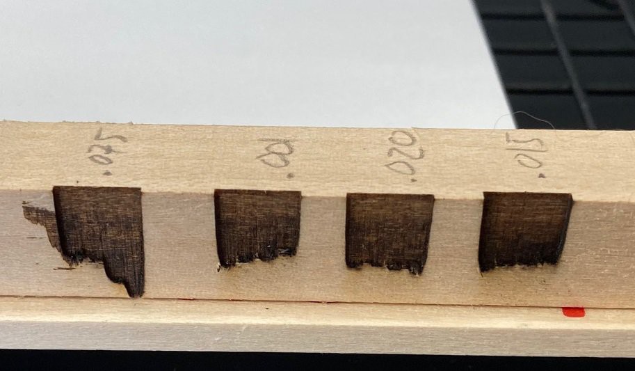
You can see that things are not exactly 1:1 here, there is a bit of a loss of depth as you increase passes and reduce power. To work this out I modified the program to scale up the power a tiny bit for each increase in pass count. After some back and forth I found that adding the following correction factor seems to normalize things:
power = (BasePower / passes) + (BasePower * 0.02 * (passes - 1))
This works fine for my laser, but it is probably highly dependent on the laser you are using. I have no explanation for this, The laser power is in fact linear so the error is not coming from there. There is a small amount of overlap between passes, it is possible that the spot size grows with power and that is causing the error. In other words this could be a flaw in my test, not a flaw in the formula.
Anyway I hope to run the same test again, but this time varying speed and power to try and maintain the same depth of cut. Hopefully that will work out well and show there is a solid relationship between speed and power as well.
-
Laser Profile
03/30/2022 at 05:14 • 0 commentsHere is a project have been working on for several weeks now. I'm glad I finally have a chance to show it off.
So previously I stumbled onto the following formula that shows the relationship between speed, power and cut depth. This basically says that doubling the power or doubling the number of passes will double the cut depth (up to a point) or depth = power. While doubling the velocity (speed) will cut the cut depth in half, or more precisely depth = 1 / speed.
![]()
I ran a few experiments that illustrated this nicely, but they only capture one slice of the full picture.
![]()
To better illustrate how all this works I wrote a new program that draws a series of lines, spaced 0.2 mm apart while varying power in the x direction between 0% and 80% and speed in the y direction between 50 mm/min and 600 mm/min. I picked up a piece of 20 mm thick basswood to run this experiment on.
![]()
After letting this run for a few hours I ended up with this finished cut. It shows the relationship very nicely. However a picture just does not do it justice, it is impossible to really see the detail without holding it in your hands.
![]()
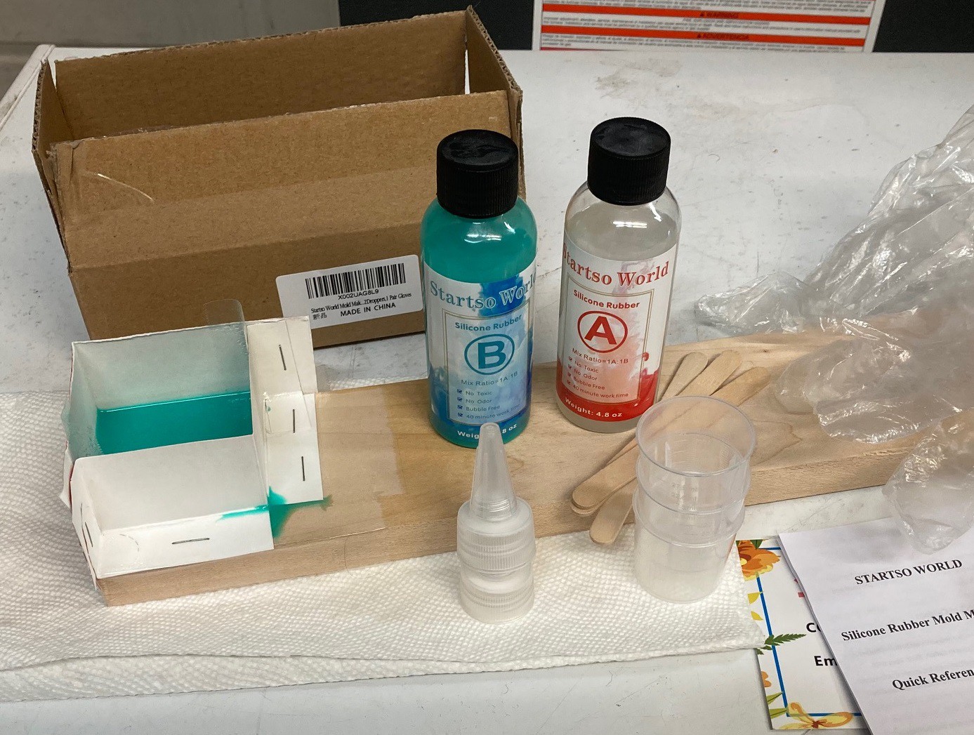
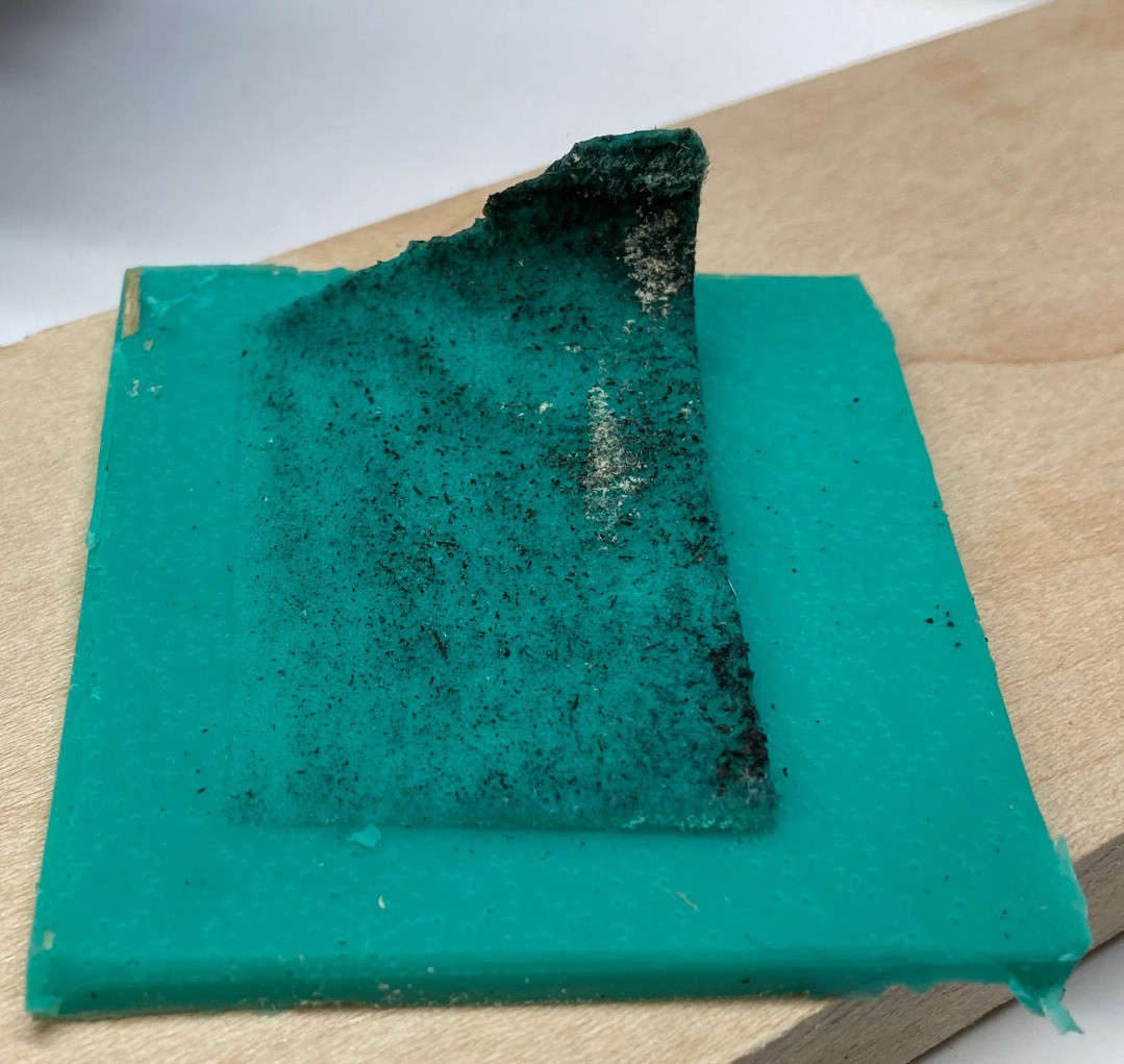
So I hit upon the idea of using a bit of silicon to make a cast of the cut so I could photograph it from several angles. I picked up the cheapest set of silicon I could find on amazon, figuring this would probably fail. However I was pleasantly surprised that it worked well.
![]()
Here is the finished cast, fresh out of the mold. I believe I have captured every part of the cut, no material was left in the mold that I could see. It is crazy how much detail it was able to pick up. The tallest part of the spike is 19mm, this NEJE A40640 laser module can cut 19 mm in one pass, crazy!
![]()
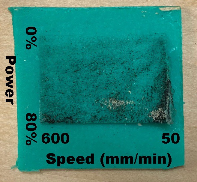
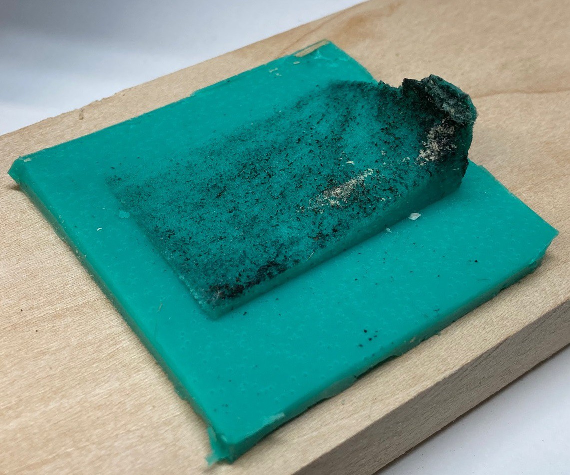
Here is a top down view of the cast. I labeled the variables on the image. The spike is in the lower right corner of the image.
![]()
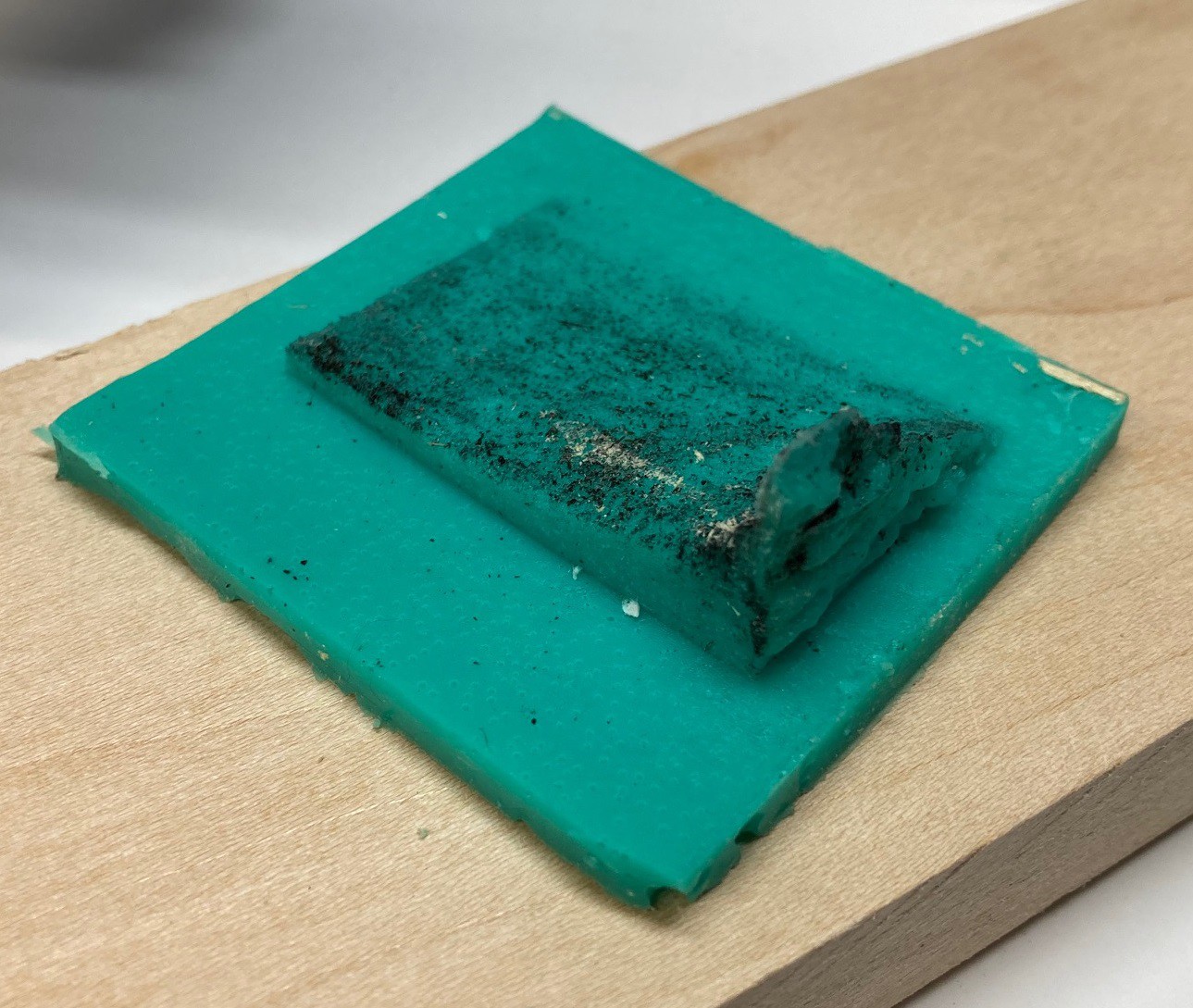
Here is a side shot showing the change in power. You can see that the resulting depth is approximately a straight line. It is a lot more straight at lower depths (faster speeds).
![]()
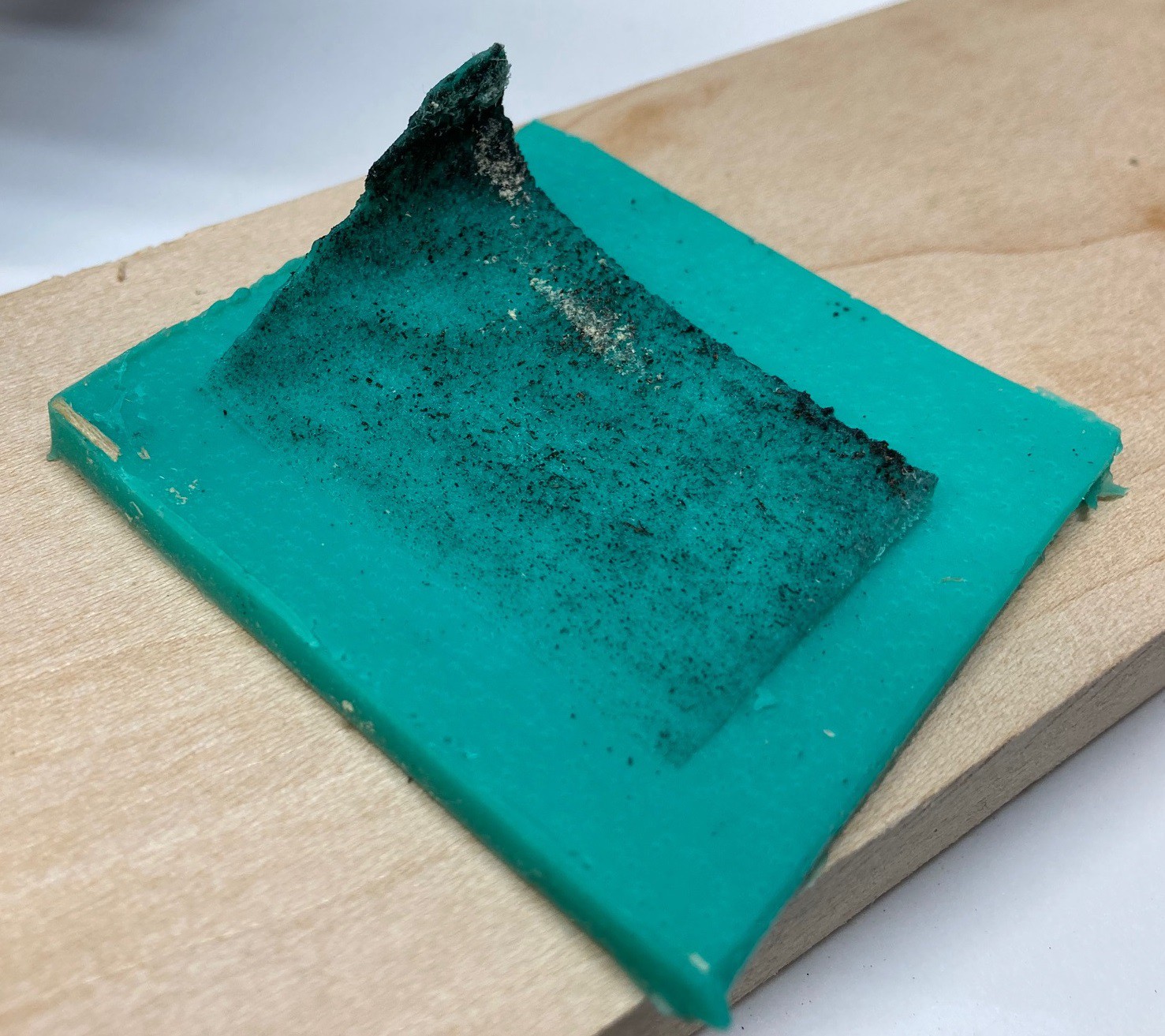
And another side shot showing the change in speed, you can easily see the inverse power (1/x) shape of the cut.
![]()
It is interesting to see both in the cut and in the cast that at the highest power at the slowest speed there is a lot of damage done to the material. We see the damage quickly fall off as the speed increases, by 100 mm/min it is looking much better.
![]()
Here are several other shots from different angles.
![]()
![]()
![]()
![]()
![]()
I have not found a good way to make topographic elevation contour lines on this, but if I did you would see that they are not straight lines but more or less C shaped curves that look something like this.
![]()
-
Don't be a Jerk
03/28/2022 at 00:40 • 0 commentsSo I have been struggling for a while now with small movements sometimes causing the machine to jerk violently and loose steps. This is more annoying than fatal but it does cause small shifts that cause the laser to not always engrave over the same spot when running multiple passes.
I spent some time trying to vary speed, acceleration, and junction deviation to try and sort this out. I found that setting either speed or acceleration super low I can sort this out, but regular movements suffer greatly. With junction deviation I was able to make things a bit worse by setting it to 1, but going below the default of 0.01 did not seem to significantly improve things at all.
Googling around for a bit, I came across this discussion that seems to have hit on the core of the problem. Basically they suggest that short segments are being overlooked by the path planner and just run at full speed without properly slowing down. I'm not sure that is exactly what is going on, but it sounds very similar to my problem at least.
To verify this I wrote a small test program that moves 30 mm in a straight line, then moves another 30 mm at an angle to that line. This loops from 0 degrees to 180 degrees in steps of 20. It worked just fine, with the planner properly slowing and reversing direction in every case, even with the machine running fairly fast at 2,000 mm/min and 200 mm/min*min for acceleration and 0.010 for junction deviation.
I wrote a second program that changes from a 30 mm straight line to a shorter 1 mm angled line followed by an another 30 mm straight line. So I jog 30 mm, jump over 1 mm and then continue on in the original direction for 30 mm. This works great at angles 0 and 20, and 80-180, but for 40 and 60 degrees I get the serious jerk.
Upon further testing I find that this jerk happens for all angles between 40 and 60 degrees off of straight at speeds above 1,000 mm/min. Varying the jog segment length I found that the fault is worse between 1 and 5 mm. Going below or above this length makes it much less noticeable. Setting the junction deviation to 0 has a small benefit but it is not enough to solve the problem Going all the way up to 4,000 mm/min speed causes a hard fault when trying to jog over at a 60 degree angle. This is very similar to the hard fault I got previously when I was using too high of a micro step count for the speeds I was running the machine at.
I dug through the code and nothing obvious jumped out at me, but to be honest I did not understand a lot of it. Things are heavily optimized in there. It is possible that this is just pushing the controller to fast and that when running both steppers at a fast update rate the controller just can't keep up. I need to try running with 4 micro steps to see if the problem goes away.
It is also possible that this is a power supply issue, I think my supply is large enough but this move is asking a lot of the whole system and going up to a 24v 6a supply (from 24v 3a) may be what is needed. And of course it is just as likely that this is an issue with the way the motion planner works and I will need to move off of GRBL to fix it. At least I have a reliable way to reproduce the problem, so maybe in time I can find a better solution.
-
Little of this, little of that...
03/21/2022 at 03:01 • 0 commentsThings have been slow this week, but I was able to get a few small projects finished.
![]()
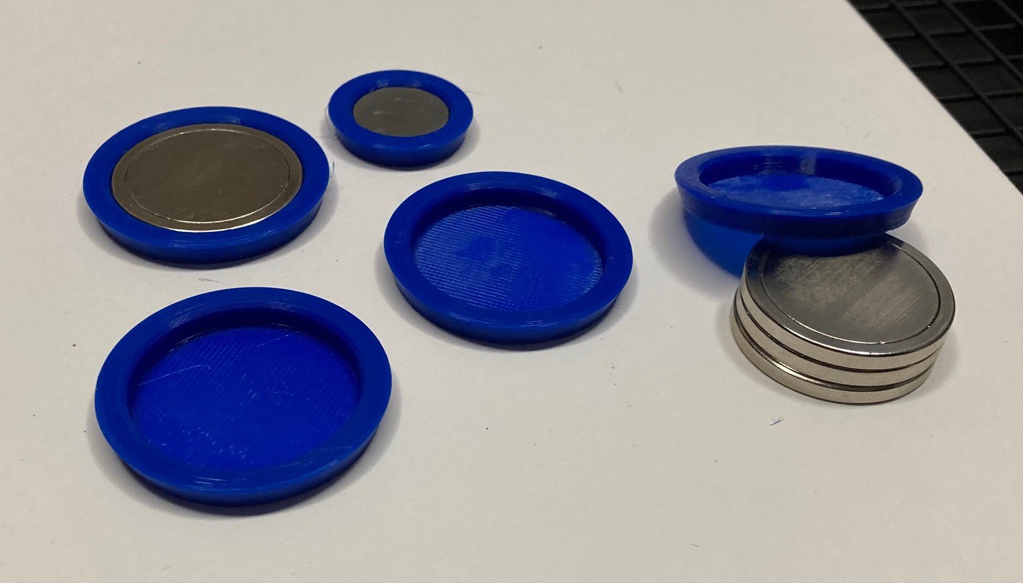
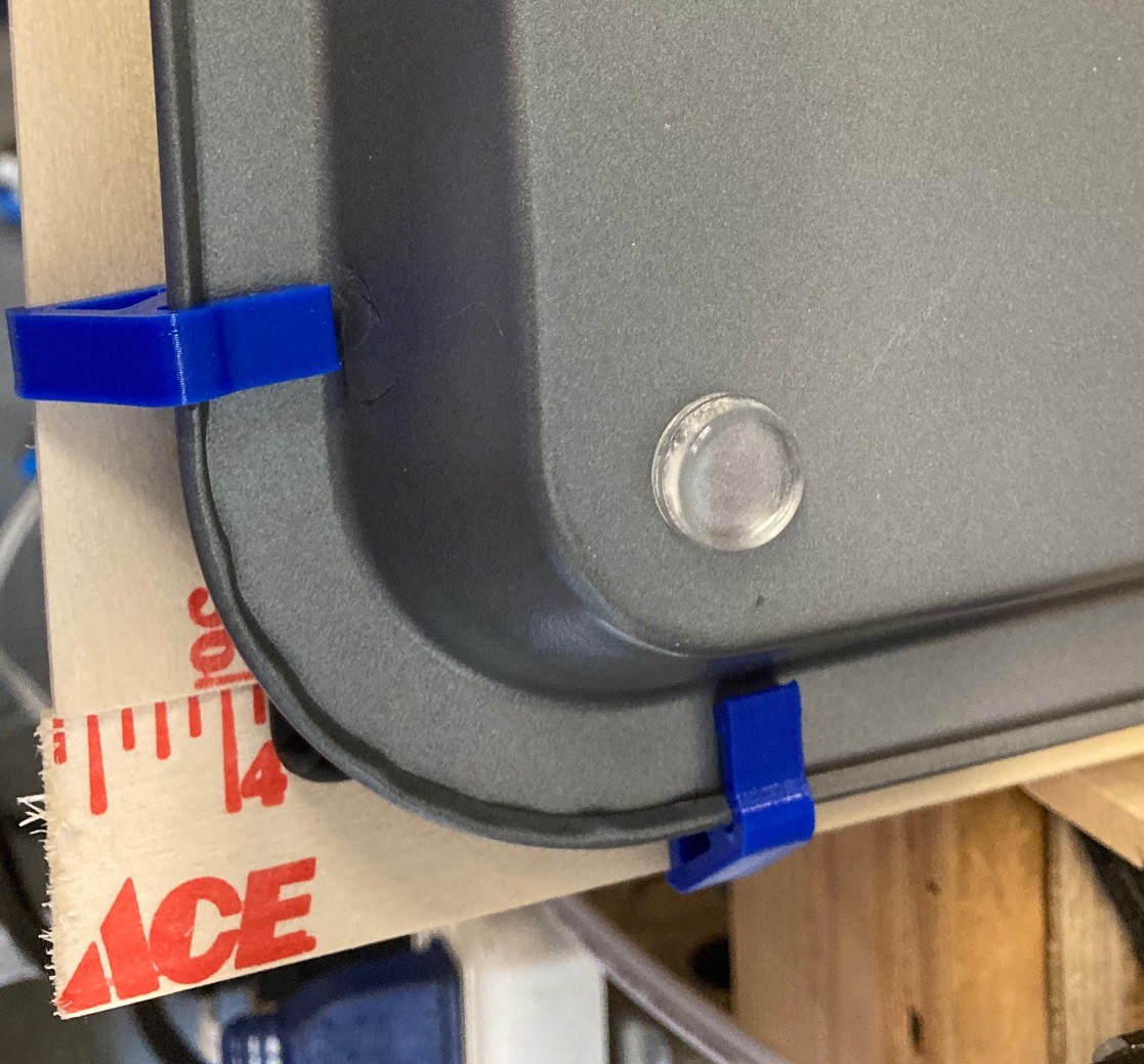
I picked up these 30 mm magnets a while ago to help hold down my material when cutting with the laser. They work fine, but they are a real pain to separate when stacked up together. To help things along I printed these simple holders that give the magnets a bevel to grip on, and that adds a few mm of distance at the top so they can be pried apart easier.
![]()
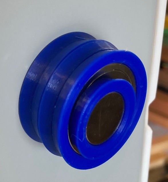
I used a few drops of super glue to hold the magnets in place, and I alternated the orientation of the magnets so they could be stored in pairs easily. There working great, I have not had any trouble separating them since.
![]()
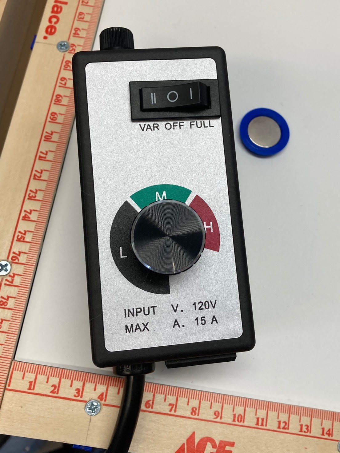
A while ago I picked up this variable speed controller for my shop-vac to try and vary the suction, and to try and quiet things down.
![]()
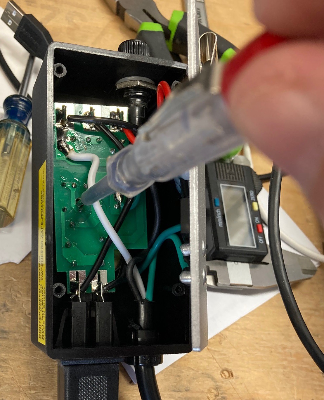
It turns out there is a potentiometer you can adjust inside the unit to set the range on the speed controller. You want to carefully take things apart, then set it to its minimum speed and adjust the potentiometer till the motor your driving starts to complain, then back it off a bit from there. Be very careful here, your exposed to mains voltage, don't touch anything. Doing this I was able to bring both the suction and volume down quite a bit. It is still an annoying sound, but you can't have everything.
![]()
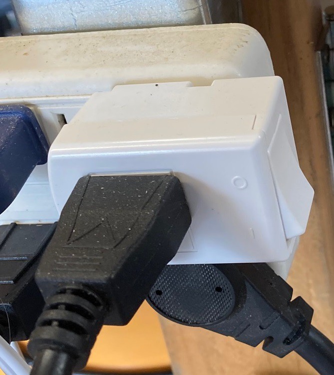
I also picked up this switch for my air compressor. It is much nicer than plugging and unplugging it all the time.
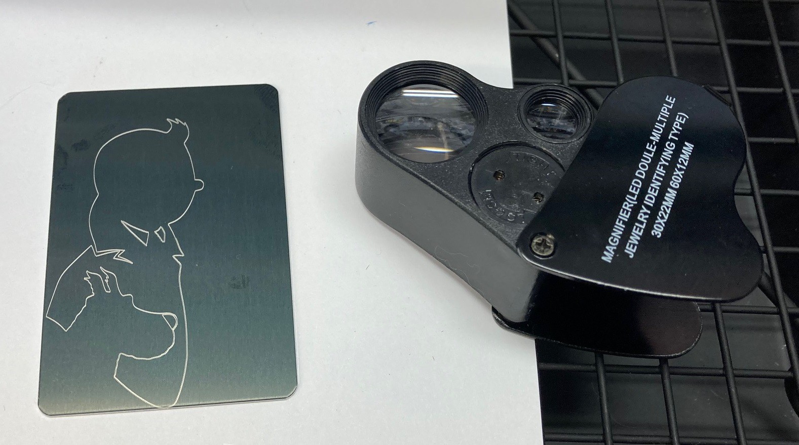
When I was trying to speed up my feed rate to make pocket hugs faster I stumbled across an issue with the steppers missing steps when burning my Tin-Tin image at 1500 mm/min. I figured I would just need to dial down on the acceleration to make this work, however that does not seem to be working.
![]()
I tried accelerations from 10 mm/sec*sec to 200 mm/sec*sec and none of them completely solved the problem. Even in the most extreme cases there was still some loss of steps.
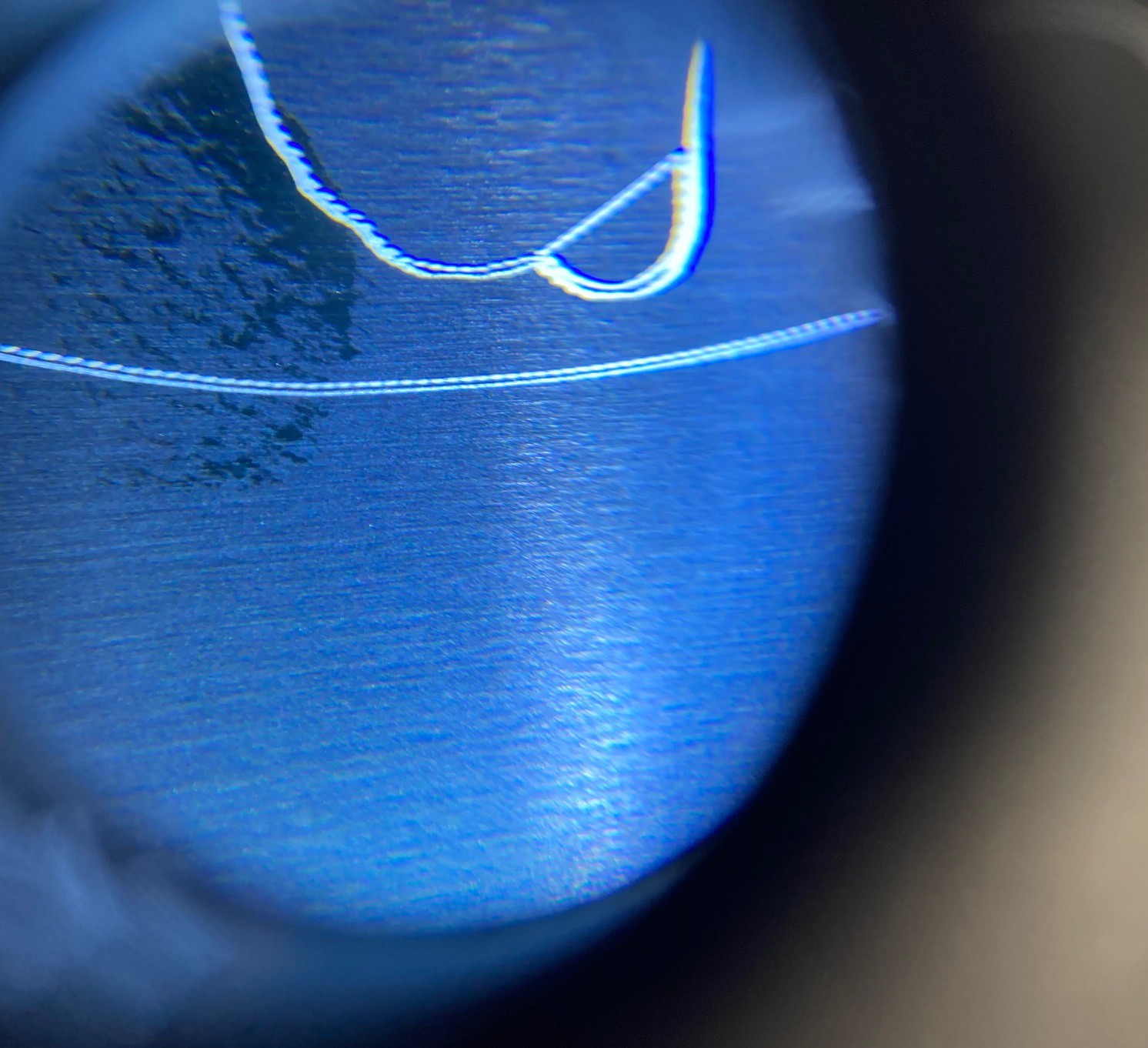
![]()
You can verify this by etching the same image twice and using a loop to see if the lines shifted.
I need to play around with junction deviation to see if that is a better way to approach this. It seems this only happens when rapidly changing direction so there is some hope that this will help.
-
Bed of Roses
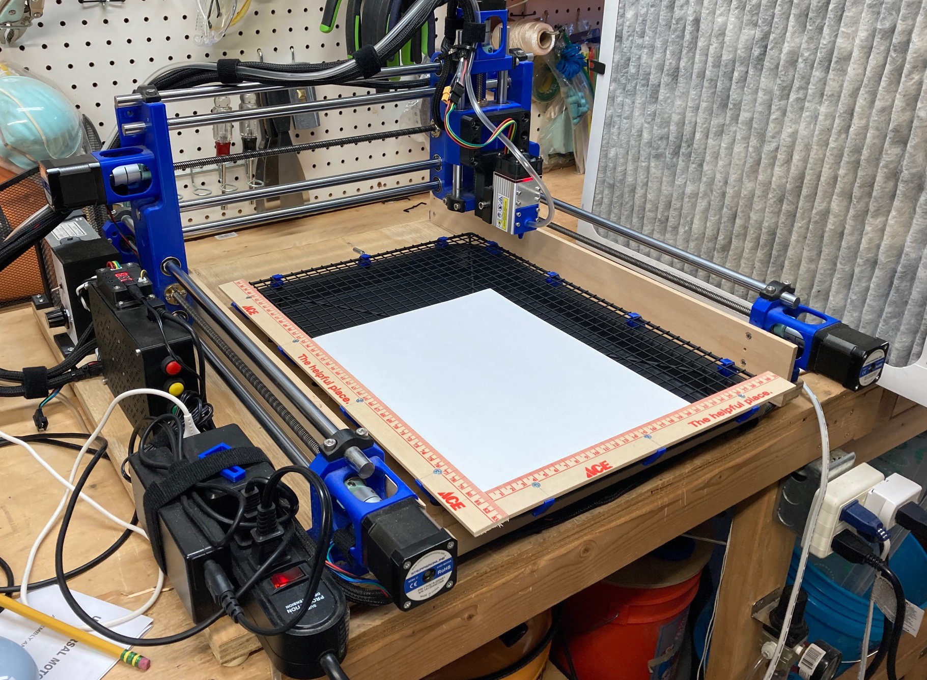
03/14/2022 at 01:58 • 0 commentsSo I decided to fix up my new laser engraving bed and see if I could not make it even better.
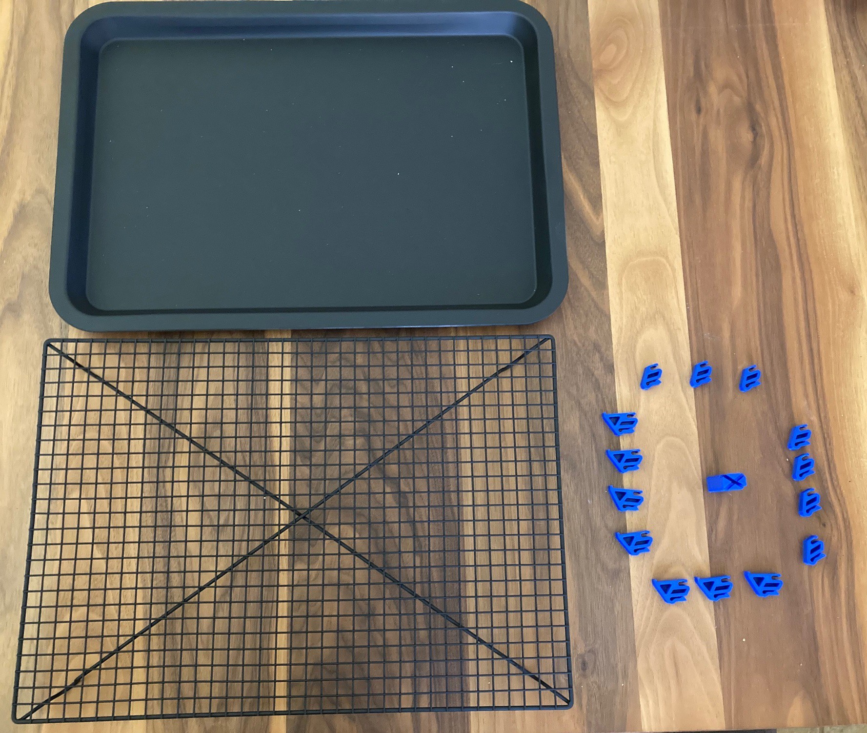
![]()
I wanted to stabilize it, and make it flatter and also provide a way to consistently lay out parts on it. To help that along I painted everything matt black to reduce the flashback and printed out little standoffs to hold the wire rack at a fixed height above the base so the smoke is not trapped below. I added a center standoff to help fight some sag in the bed and further stiffen things up as well.
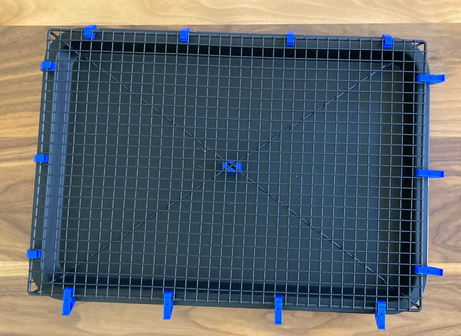
![]()
It is a bit tight but once you snap it all together the structure is very solid.
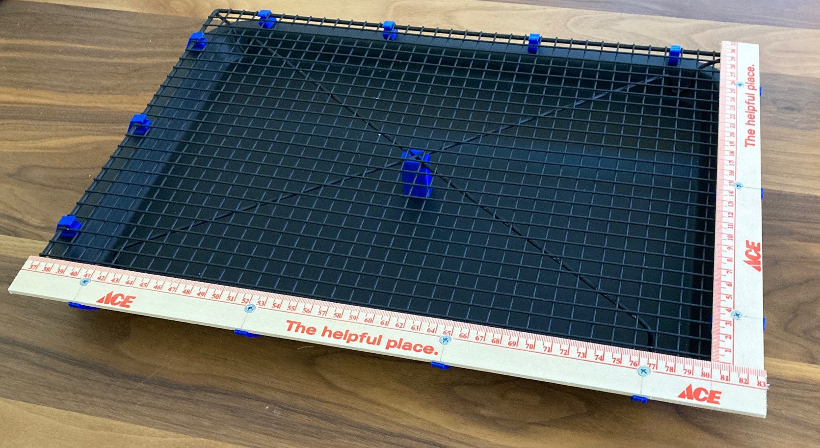
![]()
I printed half the standoffs with a little extension so I could use a yardstick as a reference edge to hold the material square to the bed.
![]()
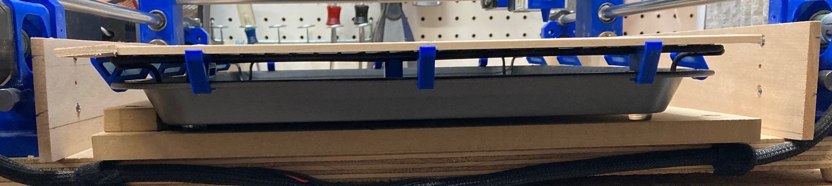
Finally since the pan was not perfectly flat on the bottom I added in some rubber feet to stop it from rocking and to provide a more solid grip on the bed.
![]()
My spoiler board has an edge installed on it, and I was able to push the laser bed up square to that. I added a pin in the spoiler board at the far end as well to help located the bed in the Y direction.
![]()
In the end I have a working bed size of 430x300 mm, with a perfectly square reference edge and only a mm of deviation across the whole bed.
![]()
in the end I probably put $20 into this, and ended up with a bed that is nearly as good as anything out there.
You can find the stl files over at Thingiverse, and I wrote this up as its own project here.
-
Hug-A-Bug
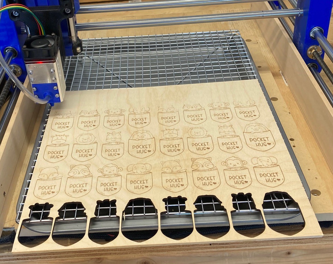
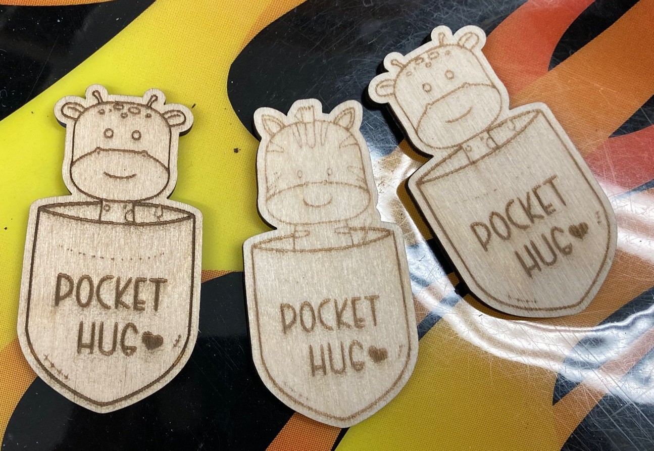
03/07/2022 at 03:15 • 0 commentsI found the time to test out cutting a full sheet of pocket hugs, well actually 3 of 4 rows since I had already cut one row earlier with my old laser. Using my NEJE A40640 dual diode module and engraving at 6,000 mm/min, 80% power, and 0.15 mm line offset and cutting at 200 mm/min, 80% power and one pass I was able to cut 3 lines of pocket hugs in 77 minutes, with 64 minutes to engrave and 13 minutes to cut. By my estimates I could have done the full sheet in 103 minutes. That is significantly faster than my first attempt that would have taken over 7 hours, more than 4x faster in fact.
My machine was making quite a bit of noise and vibration trying to run at 6,000 mm/min. It made it through but it is pushing things. If your really looking to run high speed in a production type setting your probably better off buying an open frame laser built specifically for this rather than using a heavier CNC machine. Or better yet get a proper CO2 laser with an enclosure. Still I'm glad to have the ability to process a reasonable amount of wood in a time frame I could actually commit too.
![]()
Before I ran the full sheet I ran a test cut of one piece using the same parameters. Comparing my test cut to ones from the full sheet there is quite a difference in how dark and well defined the engraving is. I suspect the single piece was small enough that the machine was unable to accelerate up to the full 6,000 mm/min. If I run this again I will try it at only 5,000 mm/min to see if I cant make the engraving darker.
Both the second and third pocket hug were engraved at the same time, yet the second one is visibly lighter. There must be more than just speed going on, I suspect there is some variance in the surface that affects its ability to burn.
![]()
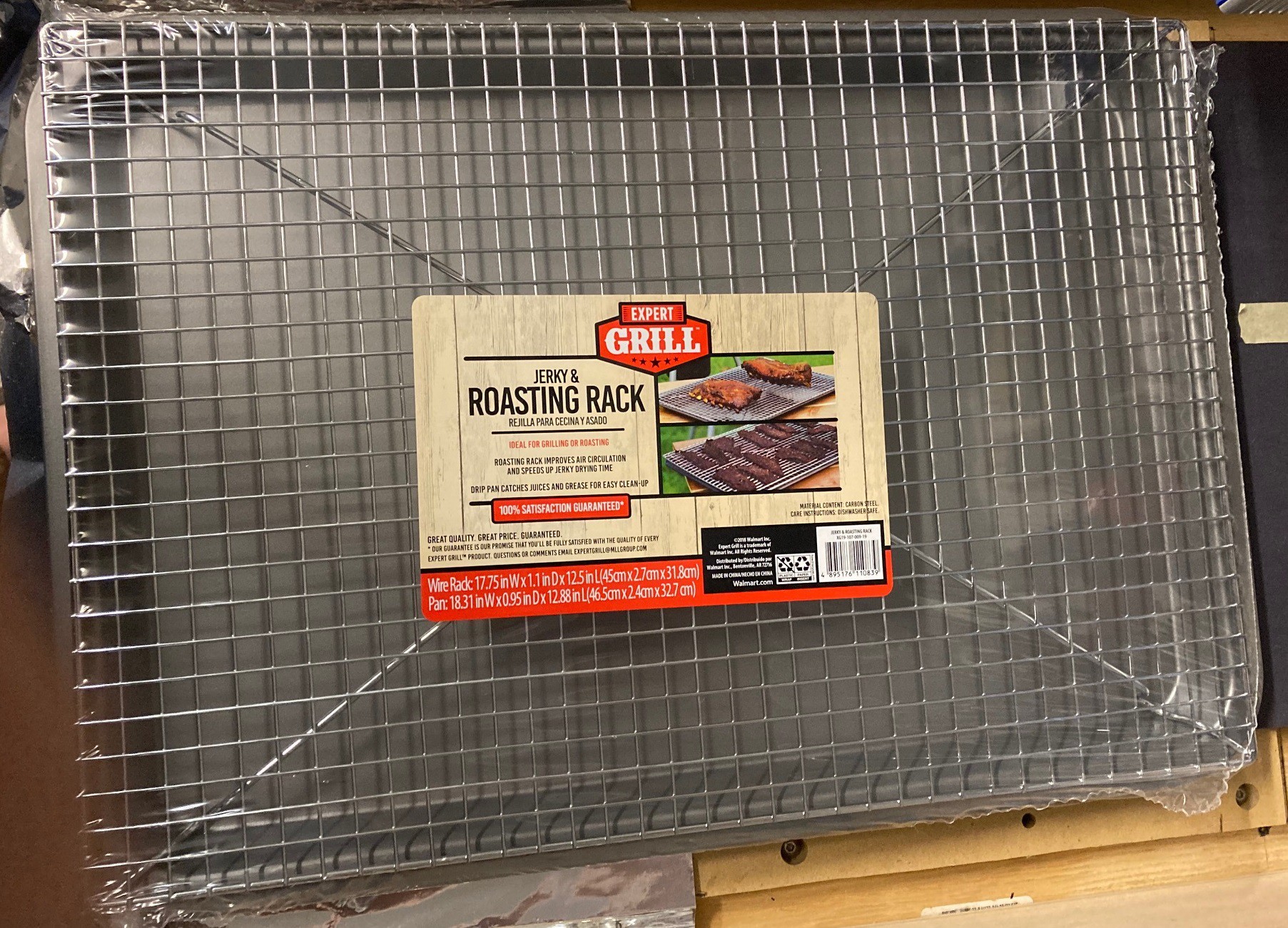
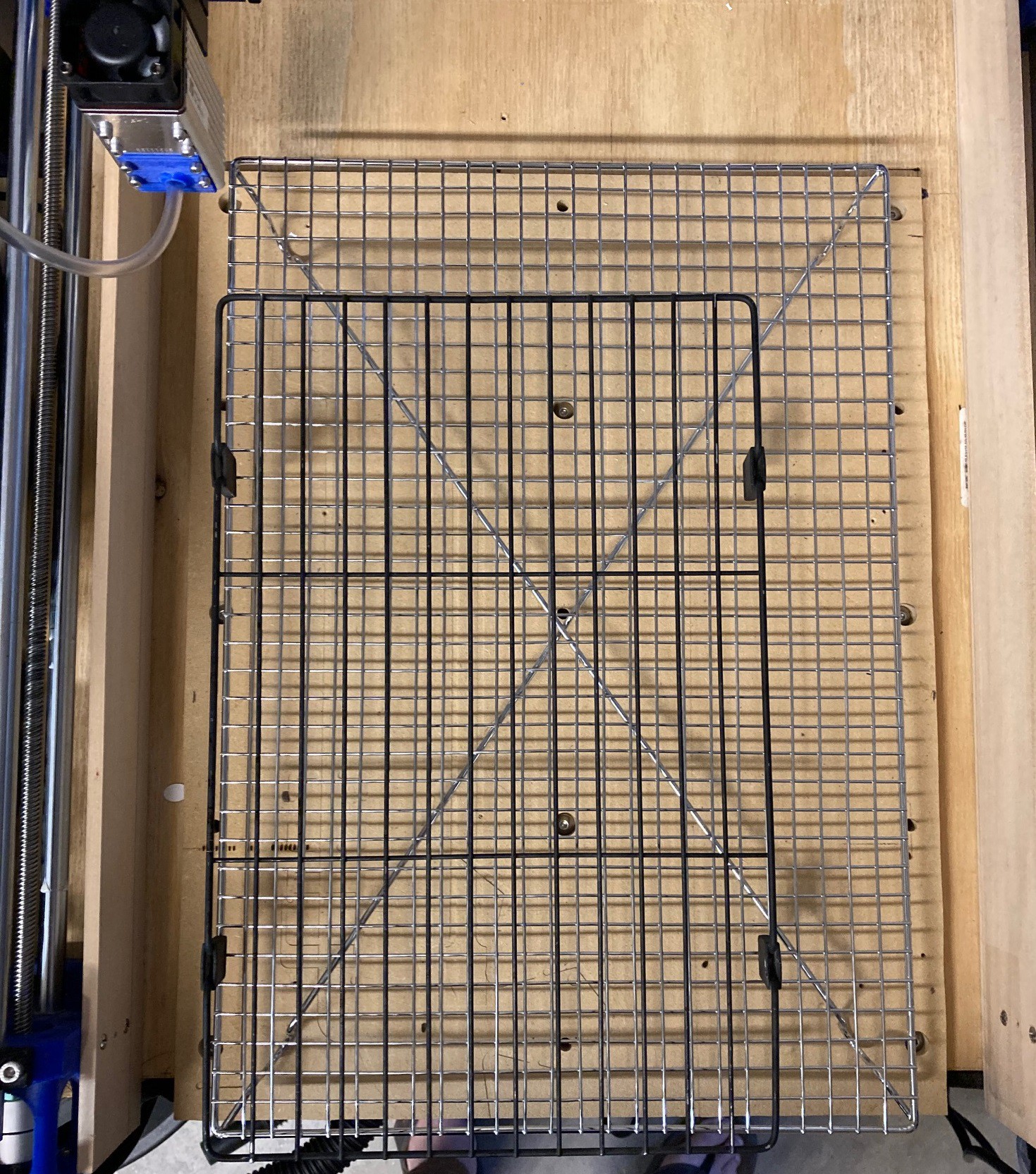
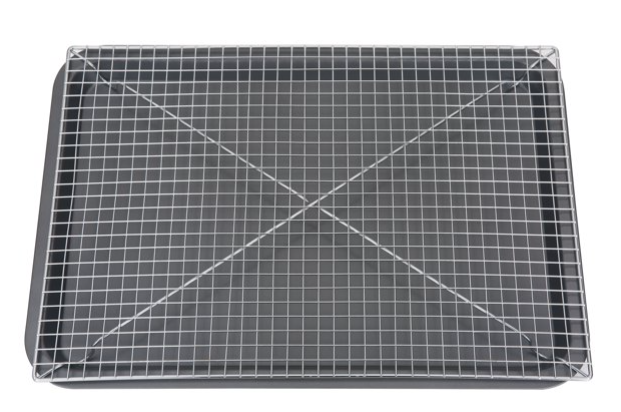
I picked up a jerky drying rack from Walmart for $9, this is very similar to my previous baking sheet and cooling rack but it is both cheaper and larger and the rack extends over the lip of the drip tray so the edge of the pan does not interfere when using pieces larger than the rack.
![]()
The rack also has a grid pattern and is better reinforced than my old rack. It is large enough to fit a 12"x12" piece of wood completely on the rack. Still not quite as large as my working volume, but it is close and for pennies on the dollar compared to a honeycomb rack.
![]()
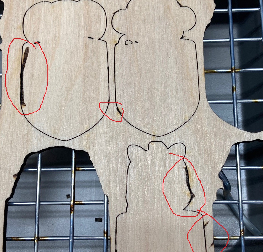
One problem with this rack is that it is very shiny and that combined with the extra power of the new laser and I'm getting a lot of flashback on the bottom side of my material. I have a can of mat black paint to try and tame this down a bit, hopefully it will help.
![]()
I'm planning on printing up some spacers to help secure the rack and pan to a piece of wood while providing some ventilation below the rack, and hopefully holding the rack rigid and level as well.
![]()
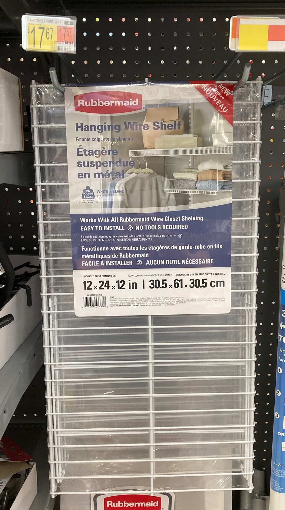
I came across the above rack at Walmart while looking around. It is very sturdy and could also make a nice bed. It is at least another possible choice.
-
Cut-Rite
03/05/2022 at 17:19 • 0 commentsSo previously I came up (well dug up) a mathematical relationship between speed and power. And I wrote a simple program to test this out by varying both while cutting. That test was lacking in many ways so I decided to improve things.
![]()
For one I was using pine to test with, and the rings in the wood were influencing the results, so I dug around my local hobby shop and found a piece of 12 mm thick basswood to test with. I was also cutting each segment as an independent step, turning the laser on and off between steps, that resulted in slightly deeper cuts at the start and end of each segment. Finally I was not properly leading in and out of the cut so the cut speed changed at the ends of the cut.
![]()
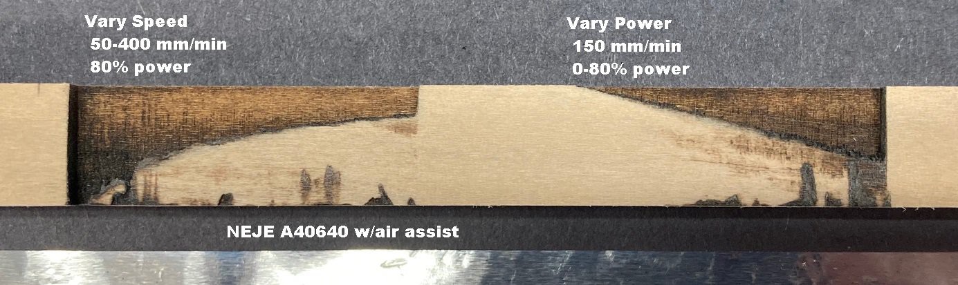
My new program uses much smaller segments (0.5mm) and much more smoothly adjusts each parameter over the range.
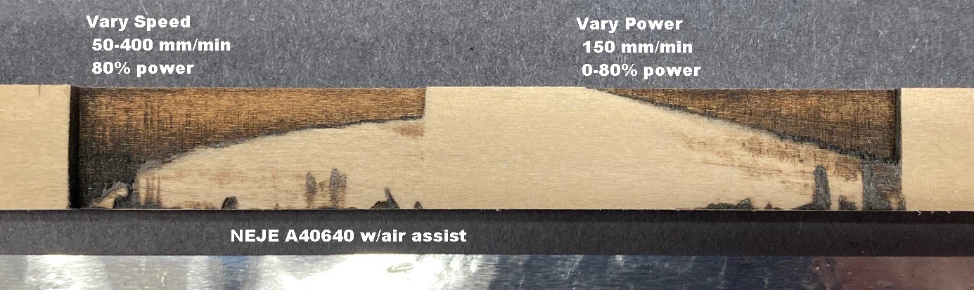
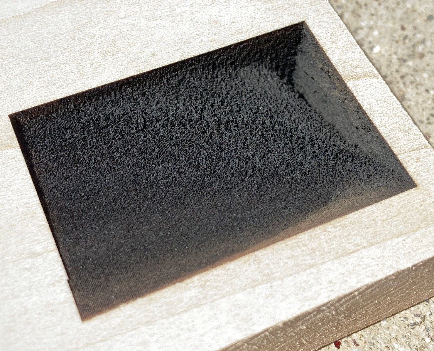
In the above image, on the left, I'm varying speed from 50-400 mm/min at 80% power with a 0.2 mm stepover between passes and focused at 22 mm below the frame with my NEJE A40640 module with air assist. You can just see that 12 mm of wood is not enough material for the slowest speeds, I probably need a piece at least 16 mm deep to fully capture everything. The cut is very clean down to about 6 mm and then it tends to get a bit scorched. 6mm is probably a reasonable working depth for this laser for day to day use, although it does have the ability to cut very deep! Notice the logarithmic (1/x) shape to the curve as we speed up the movement. We quickly loose depth at first but then the loss trails off dramatically.
On the right I varied the power from 0-80% at 150 mm/min. You can see that this is exceptionally linear now that I have my code sorted out properly. Also there is a lot less damage to the material than when running at 50 mm/min, I suspect 150-200 mm/min is a good lower bounds on speed if you want to save the material from damage.
I tried to set both of these up to minimize the chance of cutting over the same spot twice by using a 0.2 mm stepover. I probably could have pushed it a bit further but this seems to have worked much better than when using a 0.05 or 0.1 mm stepover. And the basswood is much more uniform while not being so soft that it burns excessively.
I am amazed at how narrow the kerf (waist) is on this laser, compared to my other laser there is very little variance when raising the power or lowering the speed. I did not document it, but I ran these same tests with my other laser and the results were a lot messier.
I wrote another test to vary the height while holding the speed and power constant. However that test turned out to be a dud. I struggled to get that test to produce consistent results. I think part of the problem is that my air source is moving with the laser head. It would work much better if I could cut into clear acrylic, something to try for sure if I ever get my hands on a CO2 laser.
---
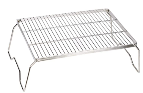
I have also been digging around some more trying to come up with a better laser bed that is strong enough not to flex too much, that is flat, and that provides plenty of ventilation and support. One idea I found is a folding camp grill for a fire pit. It is similar to a cooling rack but it has a frame built in and is made from thicker wires so it has less flex. Unfortunately being for backpacking these tend to run a bit small so I can't get one large enough to cover the full range of my laser.
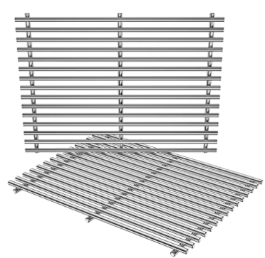
You can also get replacement racks for a bbq grill. The bars are much thicker and spaced at around 1" apart. That may be too much for holding paper, it is something to consider at least.
These are all chrome plated and lasers don't really like highly reflective surfaces. You could paint them black, that would help, but you can also get ones made out of cast iron or that are enameled black as well.
Finally Walmart sells this jerky pan set for $10 that is similar to a baking pan and cooling rack but the rack sits on top of the edge of the pan giving a more continuous surface, plus it is dirt cheap. This is unlikely to be as flat or strong as the grill racks but it is significantly cheaper and you don't have to come up with a sub surface to put it all onto.
On the sub surface side, my local hardware store sells slate tiles that are matt black and 12"x24" for $4 or so. These are probably as good as using aluminum or galvanized steel plate as a base and it cost less as well. It is a shame that sheet steel is so expensive, my big box store sells it for $30-$60 a sheet.
Anyway I may dig up an excuse to go to Walmart and pick up the jerky rack, it is not perfect but it is close enough and the price is good enough for experimentation. I would probably 3D print spacers to help tie it all together and keep it level, attaching the whole thing to a wooden base that is flat and that clips into my spoiler board.
-
Dust in the wind
03/02/2022 at 03:21 • 0 commentsSo after the last post looking at expensive filters I decided to go in the opposite direction and see what I could do with the tools I have.
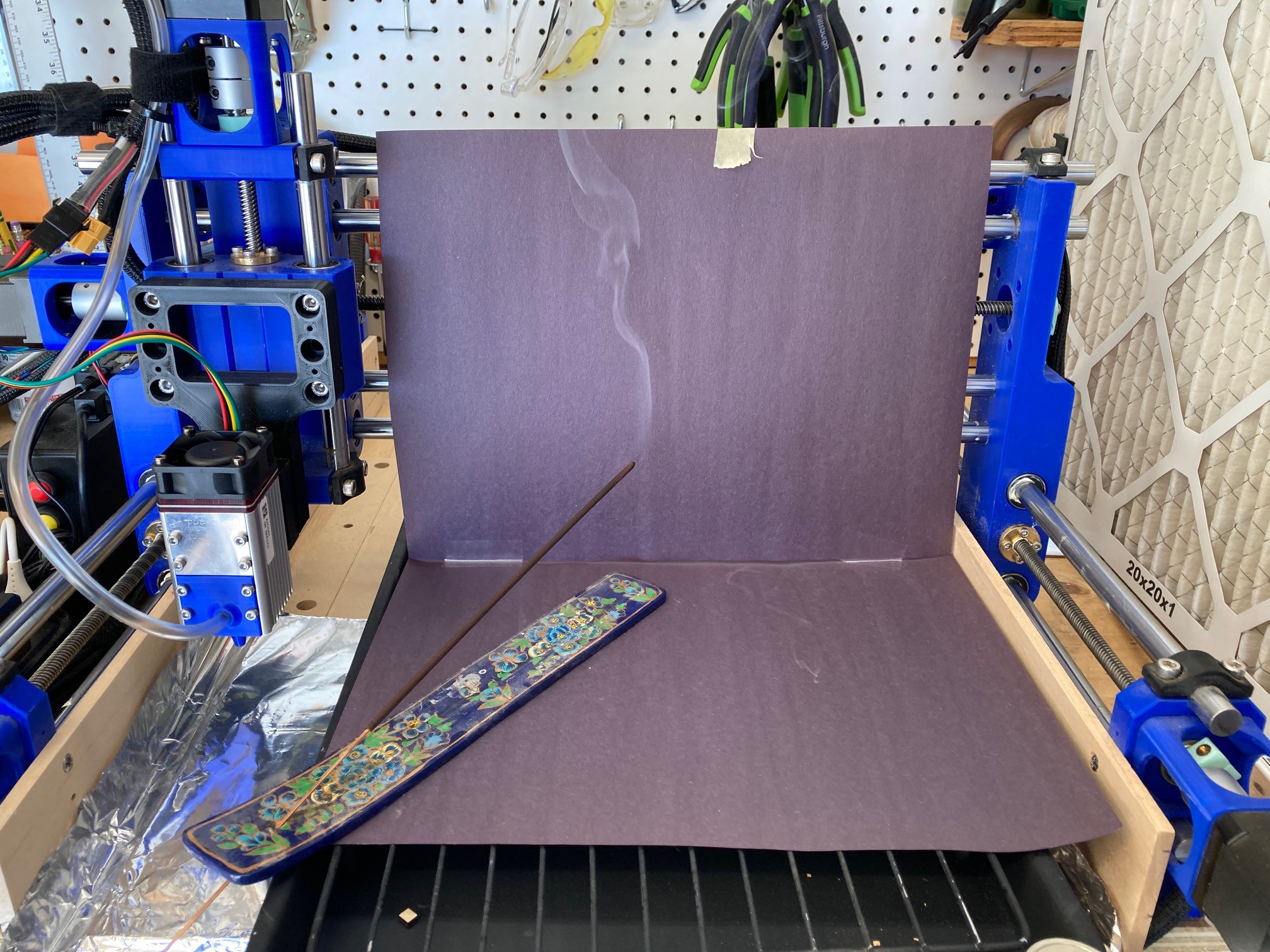
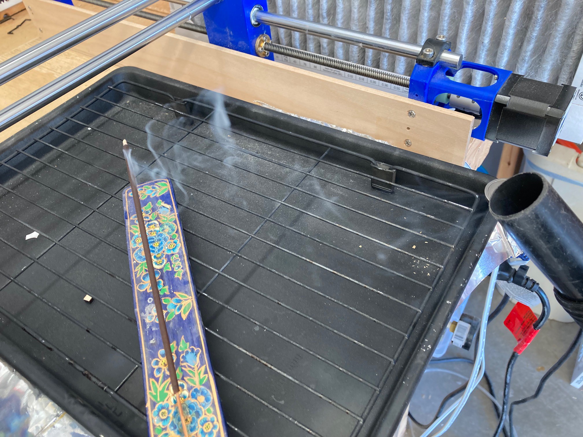
![]()
To better visualize things I borrowed an incense stick from my daughter to make a little controlled smoke. Here it is burning without any air flowing at all. I initially tried putting a black piece of paper behind the incense to make the smoke stand out. Later I tried it without the paper but I did not document things.
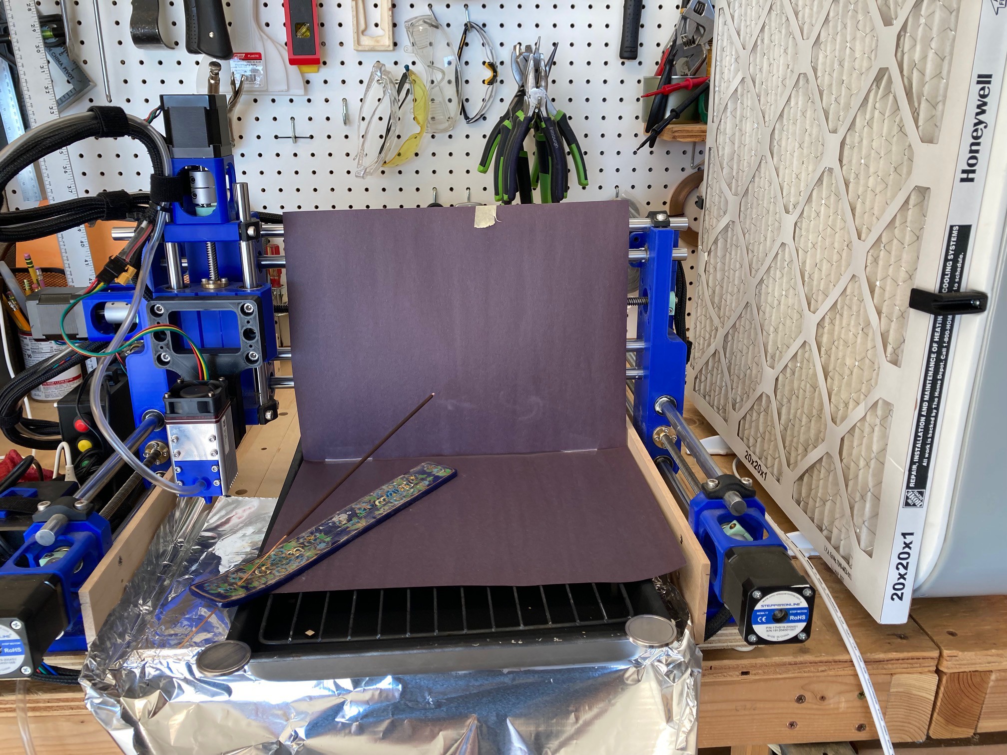
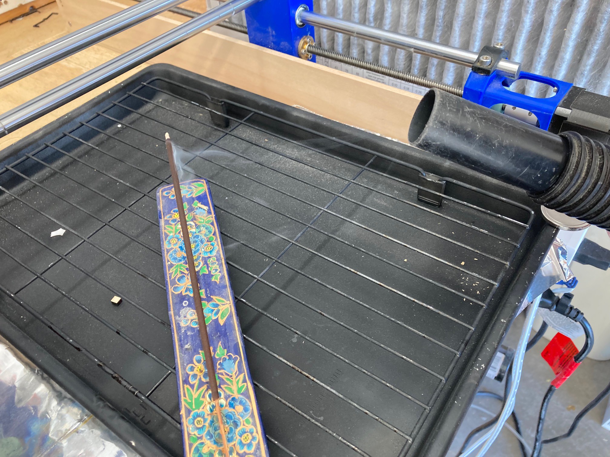
![]()
Here it is again with the fan running on high. The majority of the smoke is going into my fan but I can still smell the incense on the back side of the fan so it is not filtering out all the smoke or some is passing around the fan.
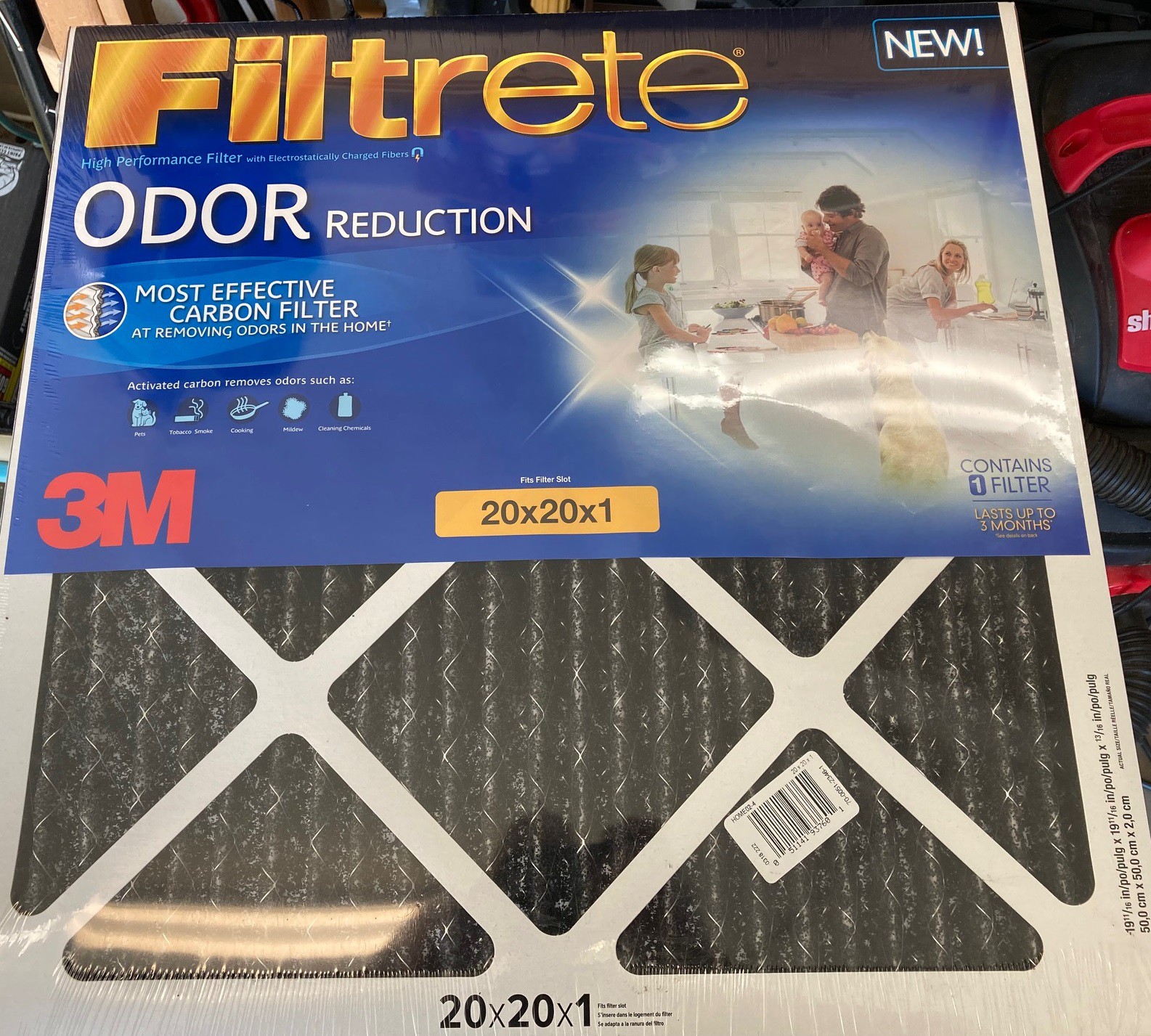
![]()
I have had this 'charcoal' filter laying in wait for my current filter to finally get clogged up. It has charcoal pellets glued to it but there are large gaps between the pellets. The air flow seems quite reduced with this filter in place and the smell test does not seem to show any improvement. I will try to give it a proper test, but I suspect this is more hype than reality. To really work you would need many layers of charcoal for the air to flow past to ensure every particle had a chance to come into contact with the pellets.
I spent some time moving my box fan around the machine to see if there was a better plaice to position it. It turns out the best place is 4" from the laser head. You may be able to make things work better by adding in baffles or enclosing everything in a box, but the closer the better.
![]()
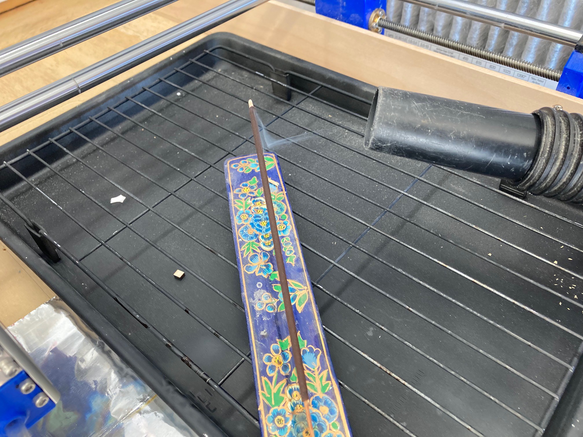
Finally I tried using my shop-vac, you can see at about a foot away the smoke is vaguely getting pulled into the nozzle.
![]()
At about 6" away it appears that all the smoke is going into the nozzle, but it is still slow.
![]()
At about 3" the air is moving very fast and all the smoke is flowing into the shop-vac. This is a very strong fan, probably much stronger than we need for a diode laser cutter, especially if we can mount the intake close to the laser itself.
Using a shop-vac as an air filter may not be the best idea. On more powerful lasers you can get a large buildup of gasses that can catch fire. The above video shows this happening a lot when cutting plexiglass. Our smaller laser is not as powerful and probably won't generate as much gas but if you use the shop-vac for collecting sawdust you may run the risk of starting a fire in your shop-vac. If you used separate hoses and filters for wood and smoke this may not be that great of a risk. A clean shop-vac should be close (in principle) to a laser air filter so there is no inherent risk other than leftover contaminants.
The shop-vac is loud, and I have not been able to find any charcoal filters for it, so it is not the best solution. However there is an outlet on the shop-vac and you could add a charcoal filter there or run a vent hose out of the work area.
Another idea is to focus on the smoke at our face and use a respirator with 3M 2097 filters with 'nuisance level' organic filters. These look like small filters but you only bring in a small amount of air (relatively) every breath. This is not as good as a proper charcoal filter but it should help out quite a bit. There are larger cartridge filters that include a lot of charcoal that you could also get for a little more money. These are more difficult to breath through, but they would also be safer.
Finally we could just run a hose out the door and put a small inline fan on it.
Nothing says we can't combine these together. It is probably a good idea to wear the respirator anyway, and venting filtered air outside is a good strategy, as is opening the garage door.
MultiBot CNC v2
A low cost 3D printed CNC that can be built with minimal tools yet is capable of great things.