David Tucker
-
Rough Cut
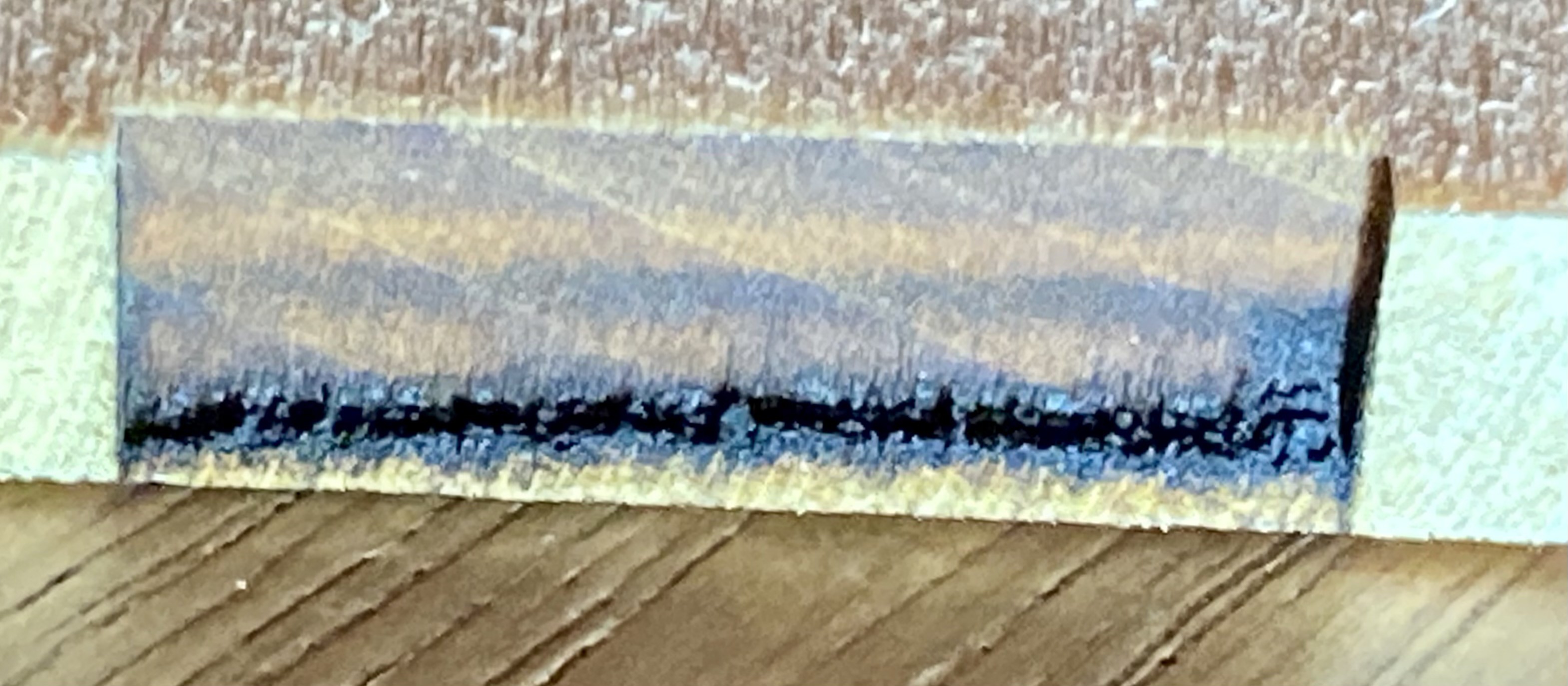
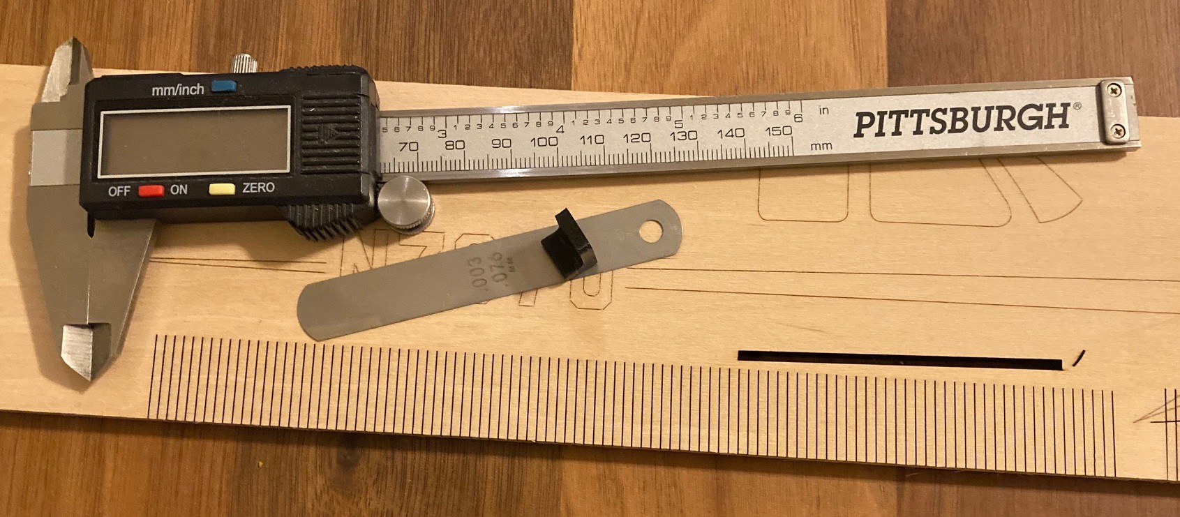
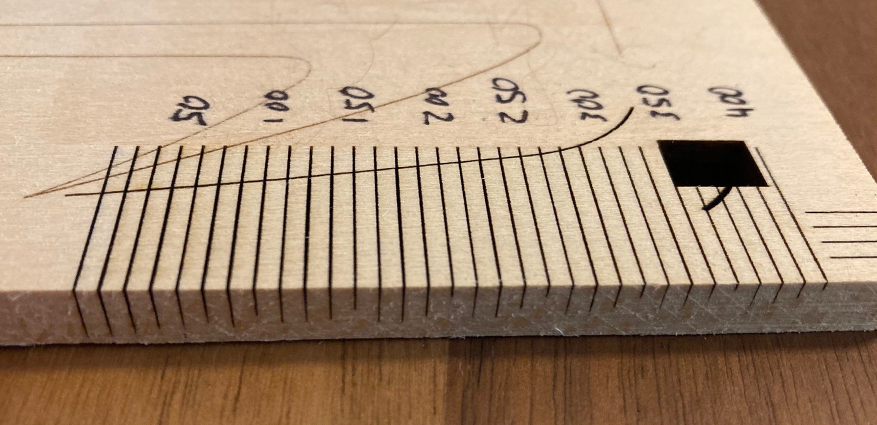
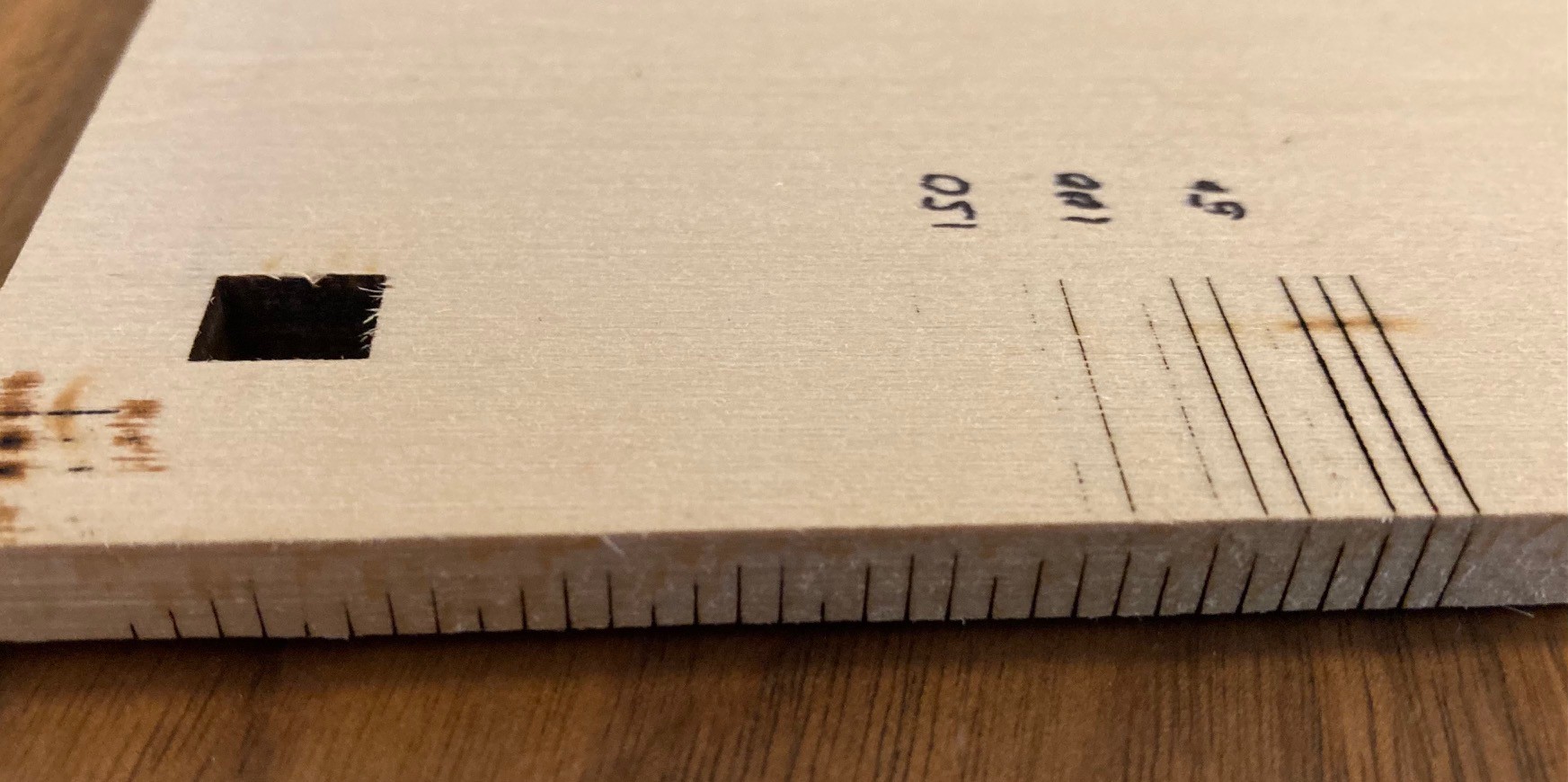
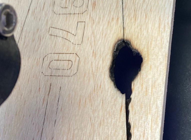
08/18/2021 at 02:09 • 0 commentsI had another idea on how to visualize what is going on inside our cuts. I ran my previous repeat line test again at 200 mm/min and 80% power, but this time I moved the next line over only 0.05mm between each run. That ensures that the laser cuts are overlapping. I then ran the test starting off the edge of a piece of 6 mm thick balsa wood and let it run until it had removed a few mm from the end.
![]()
You can see just how varied the cut is, this nicely correlates with our last test's data. What is most interesting is that it appears the wood is more dense in certain places. Even though we ran the cuts over slightly different parts of the wood, we still get high spots in roughly the same places.
It is also interesting to note that there is a touch of overburn at the very edge of the motion (at the beginning and end of motion) but otherwise we don't really see any other issues caused by the laser head accelerating up and down at the beginning and end of motion.
---
Here is a nice writeup on feeds and speeds from the Cindymill project. I did not have any other place to put it, so here seems fine.
-
Lather, rinse, repeat
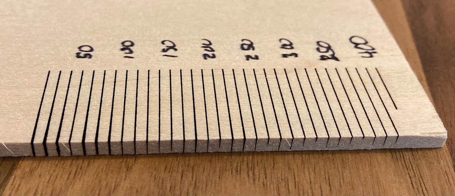
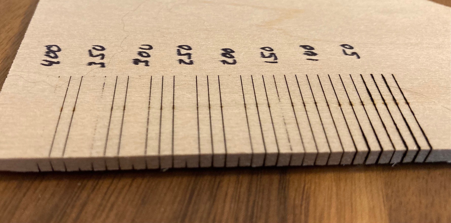
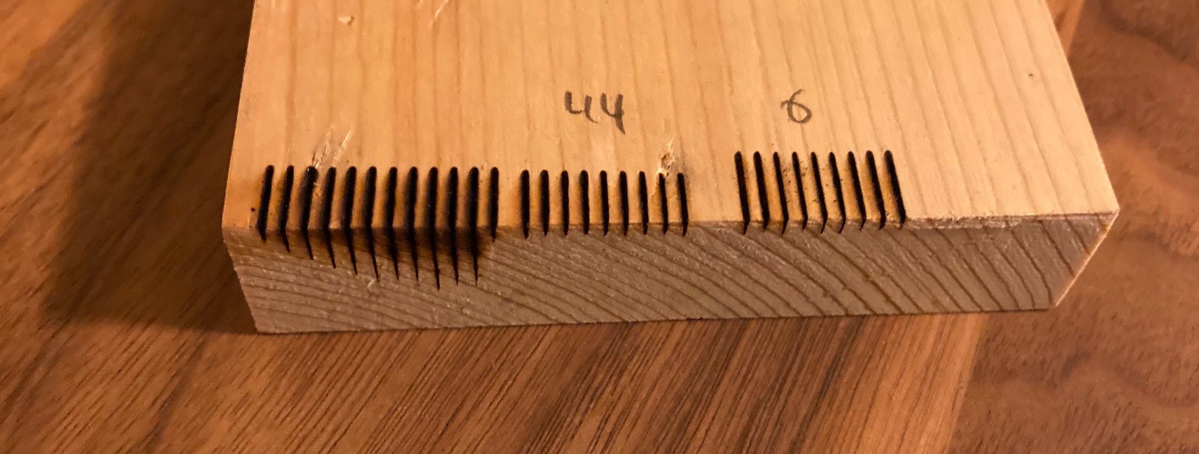
08/15/2021 at 03:55 • 0 commentsAfter running my last test I had some unexplained results where running 4 passes cut less deep than 3 passes. This is not the first time this has happened, and I don't think I can blame it on a measurement error. Anyway to try and dig a bit deeper into this I wrote a script to cut a 20 mm line at 100 mm/min and 80% power on my 30 w NEJE laser. The script cuts the same exact line over and over again, each spaced 2 mm apart. By measuring the depth of cut of each line we can see how much variation there is.
![]()
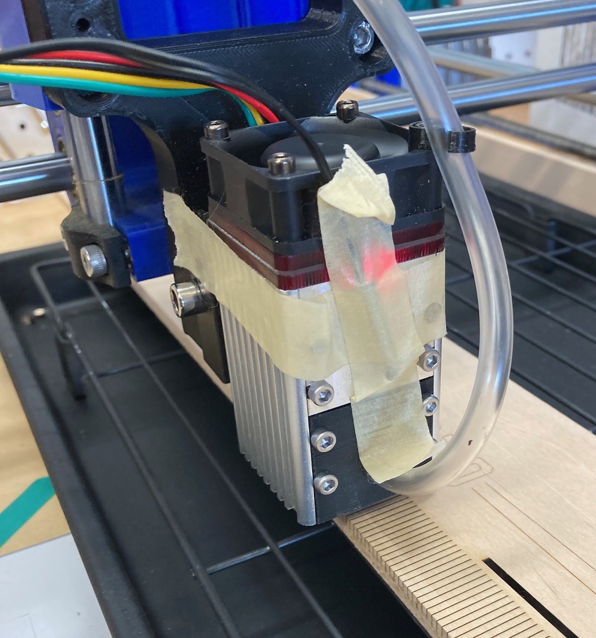
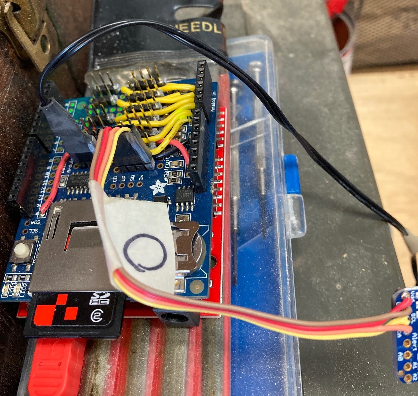
One idea I had was that the laser was heating up and loosing power when running the same cut back to back. I happened to have a temperature data logger that I made from an old Arduino a while ago, so I pulled it out and strapped one of the temperature probes to the front of the laser.
![]()
![]()
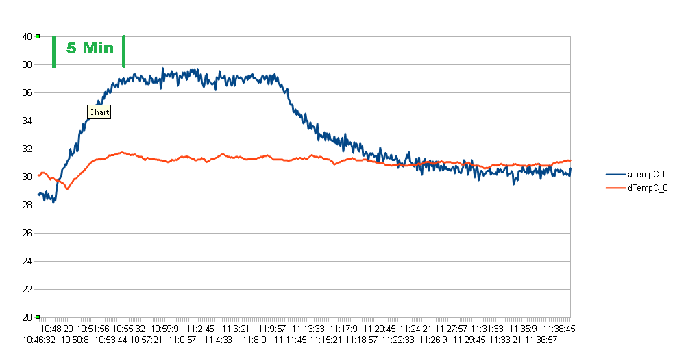
You can see from the above plot that the temperature rises from room temperature (28C or 82F) to 37 C (99F) after 5 minutes of continuous operation. I let the thermometer continue to log after the job finished, it took another 5 minutes or so for the laser to cool back down to something approaching room temperature. It would probably be best to run the fan for at least 5 minutes after finishing a job so the laser can cool down quickly.
![]()
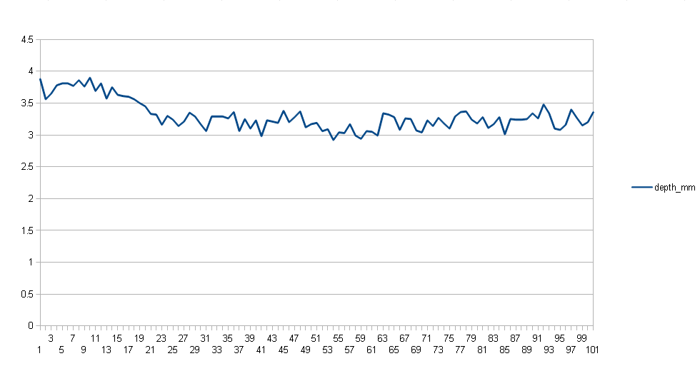
I measured the depth of cut of all 100 lines and came up with the results below. The max variance between the deepest and shallowest cut was about 25% and there seems to be an inverse correlation between the temperature of the diode and the depth of cut. It is clear that there is quite a lot of variance between cuts, and that the laser looses power as it heats up, but I don't think it is enough to explain the fact that 3 passes produces a noticeably deeper cut than 4 passes. In some cases the difference was almost 2 mm!
![]()
-
Cut above
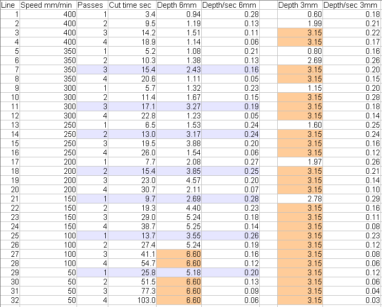
08/09/2021 at 04:46 • 0 commentsSo I ran my test program on a piece of 1/8" (3 mm) balsa wood and a piece of 1/4" (6 mm) balsa wood. I used my 30 w NEJE laser (7.5w optical power) at 80%, with speeds from 50-400 mm/min and 1-4 passes at each speed.
The thinner piece was basically cut through cleanly at almost all speed and pass combinations except for a few of the fastest single pass speeds. That limits what we can get out of this test, however it is interesting to see how much extra damage is done to the wood when cutting at the slowest speeds.
![]()
![]()
On the thicker piece of wood only a few passes managed to cut all the way through, and that only at the slowest cutting speeds did we make it through the wood. Only 50 mm/min managed to come close to cutting through the wood in one pass, and even then we would need to turn it down a bit more to guarantee a clean cut. It took two passes at 50 mm/min (52 seconds), 3 passes at 100 mm/min (41 seconds) to get through cleanly. With 4 passes at 150 mm/min (39 seconds) almost got through but we would need to slow it down a bit to get all the way through and chances are that would loose any benefits. In this case going faster with more passes seems to be giving some benefit to the cut time, but not a dramatic benefit.
![]()
![]()
I measured all the depths of cut and put them in the below chart, at the same time I recorded the time the actual cut took (minus any transit time between the passes), and finally I calculated a cut depth per second metric that may or may not have much value.
![]()
Depths marked in the orange (salmon?) color were clean through cuts. For the 3mm wood we can see that the fastest single pass through cut was 100 mm/min at 14 seconds, while the fastest through cut was 11 seconds at 300 mm/min and two passes. That is not a huge improvement but it shows you that there is some benefit to multiple passes, especially as we push the speed low enough that we start to damage the wood.
The blue (grey?) lines represent the quickest cuts at each speed that managed to make a cut deeper than 2.4 mm (an arbitrary depth). The numbers are all over the place because we are not cutting the same depth in each case, but you can see that the fastest cut was one pass at 150 mm/min (10 seconds) , with two passes at 250 mm/min (13 seconds) in second place. Clearly if you can make it through in one pass at 150 mm/min then there is no advantage to going even slower, and we see this with 50 mm/min being almost 3x slower than 150 mm/min. The interesting thing is that adding extra passes doubles the time and it is probably not the optimal way to tune cutting depth, better to tweak speeds so you can make the cut in one or two passes than trying to make it happen with 4 passes.
Once again I'm seeing a loss of performance when making 4 passes on a cut. I can't explain how 3 passes can cut deeper than 4 passes. Either the laser diode is overheating and loosing performance, or there is some sort of buildup of charred material on the 4th pass that is plugging up the kerf and skewing the measurements. I'm thinking of adding a temp sensor to the laser and doing a series of identical lines in some material to see if we can see a loss of performance and/or a build up of temperature.
-
Codify
08/08/2021 at 01:12 • 0 commentsI have been working on cleaning up my gcode test scripts and thought I would go ahead and share them here. Among other things I cleaned it up so that we can accurately time how long each cut takes. This is written in C++ and compiled with VC 2017. You can download the code here.
I'm interested in working out if running slower is better than running fast and taking multiple passes. To that end I have written a routine that will cut a series of lines at different speeds and different number of passes, all while logging out the time . The idea being that we can run the test in our chosen material, and then pick the speed and pass that cuts through the material the fastest.
![]()
![]()
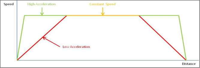
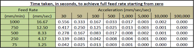
In order for this to work well we need to make sure that our acceleration settings are tuned up properly. If they are set too low then the machine will never make it to the requested speed unless you are cutting very long lines. SanSmart has a nice writeup on all of this available here, you can read the two other parts of there writeup here, and here if you are interested in the whole guide.
I'm hoping to get a chance to run this tomorrow, we will see then if it is a worthwhile test. Hopefully it runs faster and more efficient than the normal grid of squares test that varies power and speed. In this case were running at 80% power because it has the best potential for cutting without over driving the laser (extending the life of the laser) so we don't need to vary power as well. Although it may be interesting to vary power on my balsa wood piece that caught on fire, that is another experiment for another day.
-
A stitch in time...
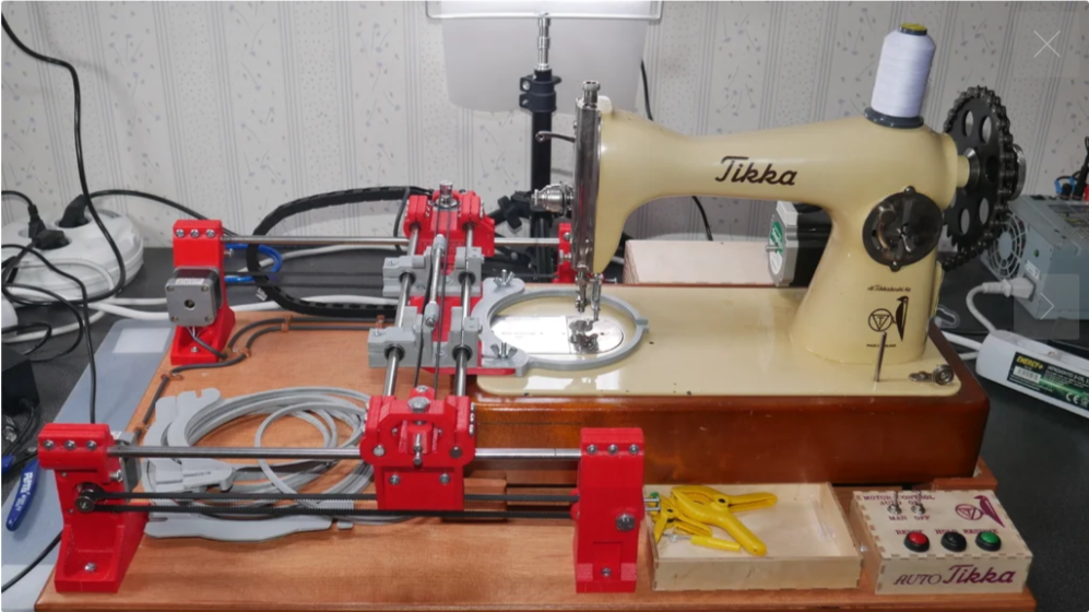
07/26/2021 at 00:10 • 0 comments![]()
I recently stumbled across this excellent looking embroidery machine build on thingiverse. It would not be hard to modify the multibot to drive an embroidery addon. You would either need to get rid of the auto squaring and just clone the Y axis steppers to free up the A axis, or you would need to unplug the Z axis stepper and use it to drive the sewing machine needle.
It is also possible that you could modify the sewing machine so it cycles once every time you send it a pulse, that way you could skip adding a stepper motor to it all together. It is possible that more modern sewing machines can operate in this mode where a foot switch cycles the needle down and up once.
-
Spaceboy I've missed you...
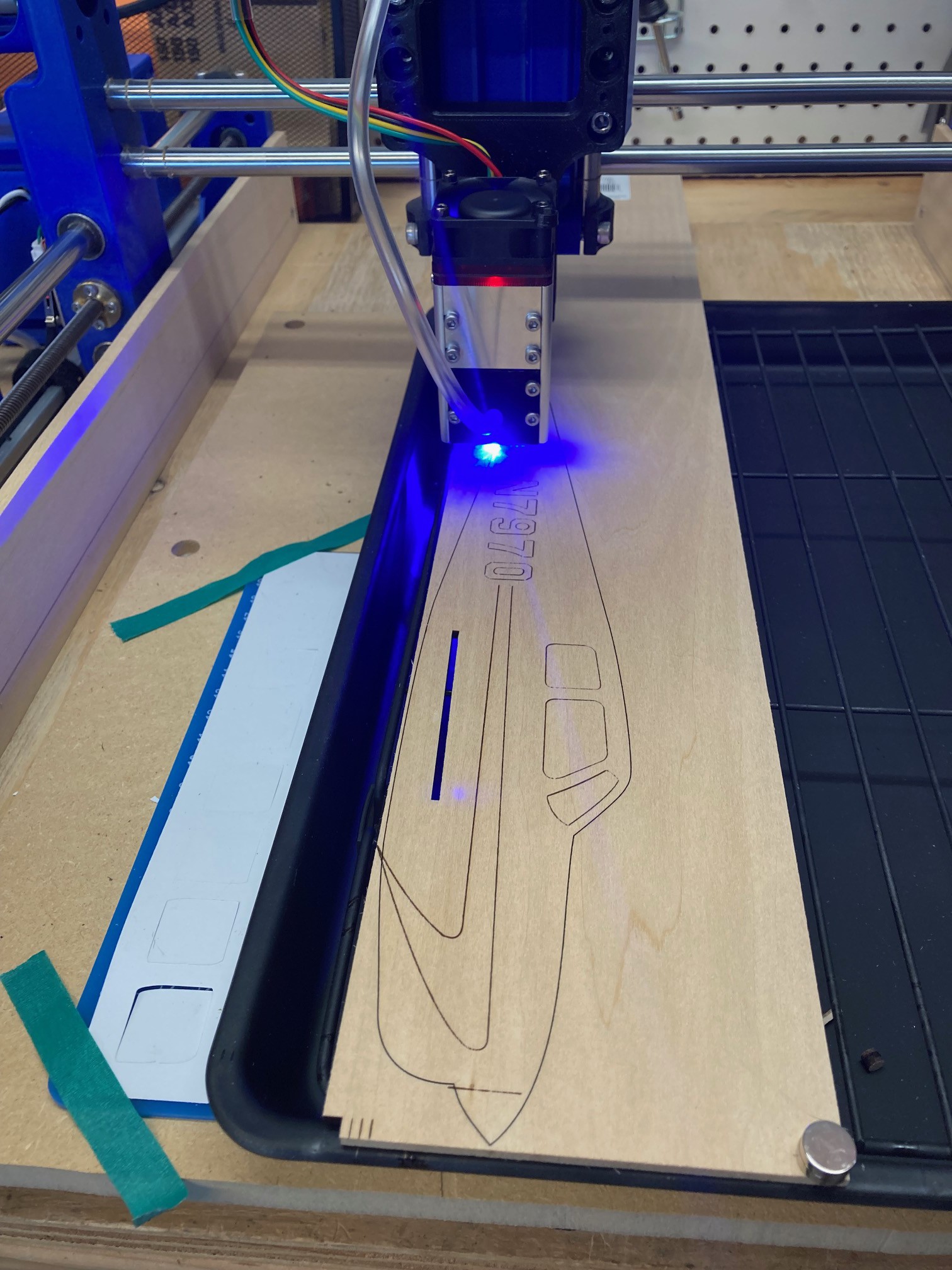
07/25/2021 at 20:03 • 0 commentsI finally got a new piece of 1/8" balsa wood that is denser and easier to cut with the laser. I was able to cut it out at 80% power, 150 mm/min, and 2 passes. It took over 20 minutes to cut out the fuselage at this rate, much too slow to be useful.
![]()
I probably could have gone with 200 mm/min to make it go a bit faster, but even that would not be enough to really make this worth the effort. I think going with the larger 40 watt laser you could speed this up to 400 mm/min at 2 passes and end up with less than 10 minutes per cut. That would be fast enough to be worthwhile (it would be close to the time it would take you to cut it out by hand). A 5 minute cut would be even better, that would be faster than what you could do by hand and with better accuracy, but you probably need to go over to a K40 laser to get those speeds.
There is a small shift in the engraving above, I moved the work over a bit between engraving and cutting because I got my starting position off by a bit and the cut was not going to start on the wood.
![]()
I tried gluing this up with super glue but it was soaking too much into the wood and did not form a strong bond, maybe a thicker glue would have worked better. In the end I used some wood glue and that seems to be holding well.
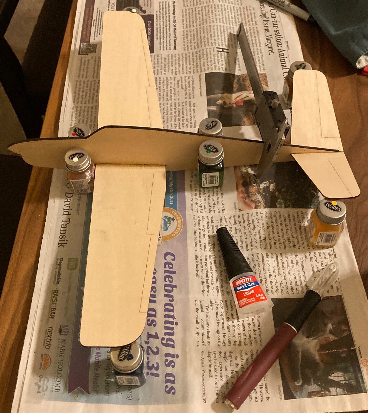
I went ahead and used the paint bottles to set dihedral just like the original plans, that seemed to work well. To set the tail I needed to add weight to the body to help keep it from lifting up. I let it dry for an hour then released the pressure and double checked that the tail was well aligned with the wings. The wood glue is slow to dry so you have time to tweak it. Remember to add the braces back after you make your adjustments so the wings don't move under there own weight.
![]()
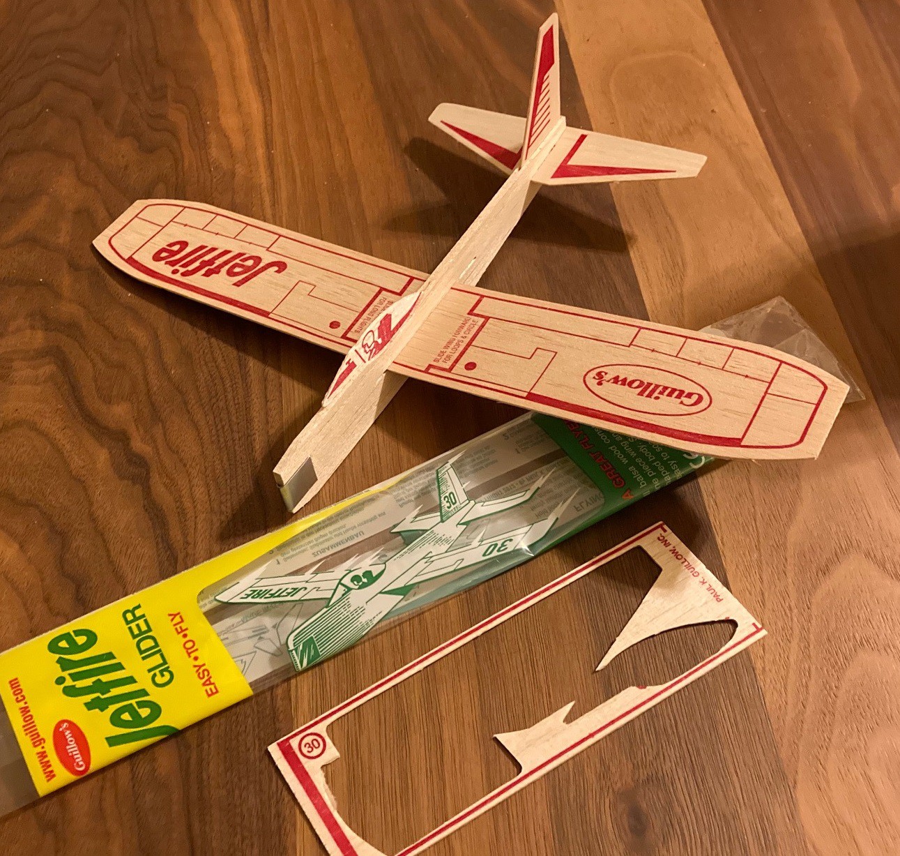
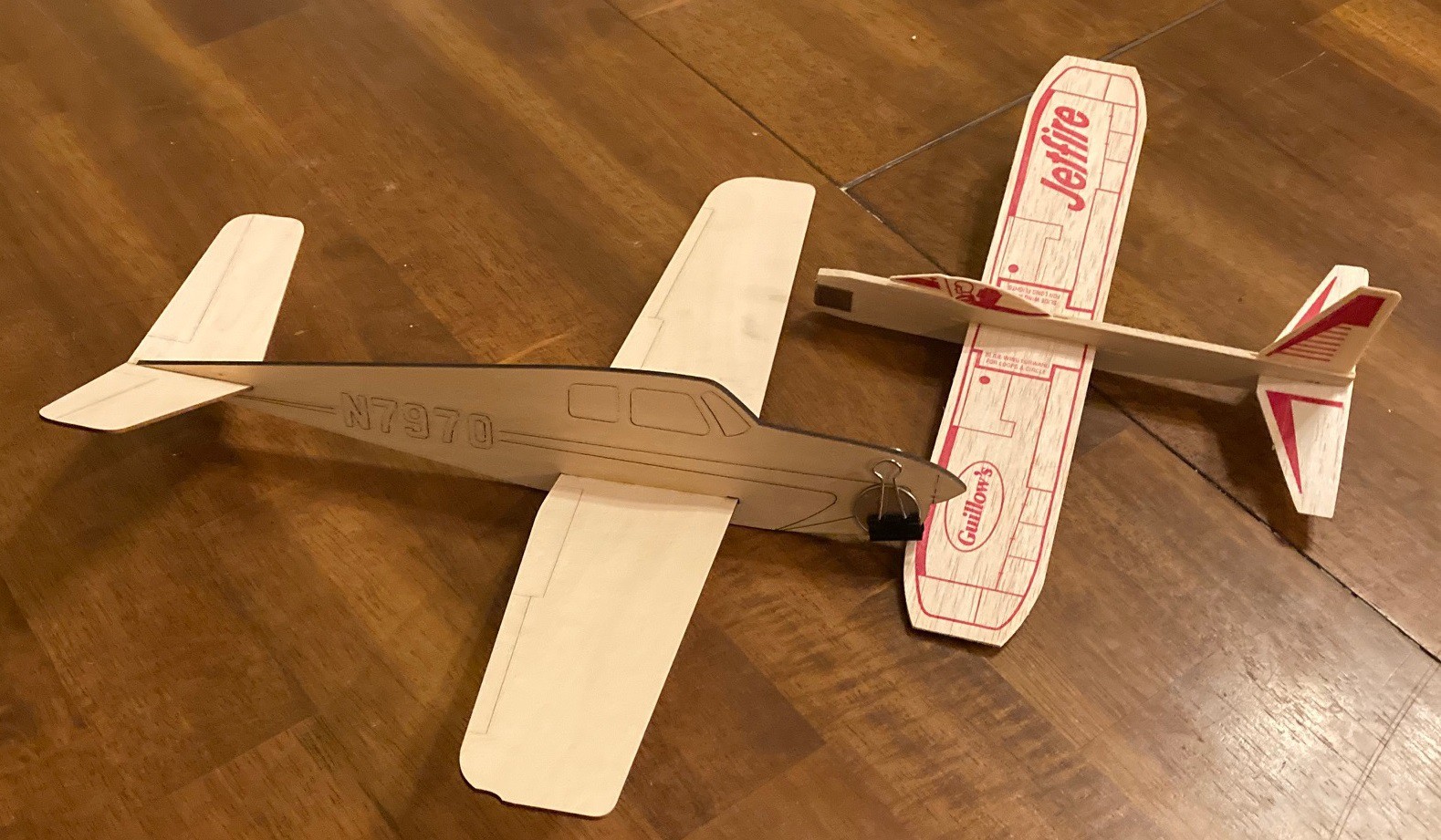
As a comparison I picked up a $3 glider from the hobby store where I picked up the balsa wood. The quality is much lower, with poorly punch cut parts and very pithy wood that can easily be snapped. Even though it is a simple design installing the pilot and tail was tricky because the wood was so soft.
![]()
The weather is wet outside so I have not had a chance to really fly either of these, but I did toss them across the room into the couch and the $3 model seems to glide better (with a light push). I think a big part of the problem is that I'm using rather dense wood for the body. I got it all from ACE hardware and they only had very dense pieces and very pithy pieces to choose from. Going to a proper hobby store would probably work better.
Anyway I won't know for sure till the weather gets better but I have some hope that my model will work better outside than the $3 one, once the wind is a factor.
To sum it up, the laser seems to be quite good at cutting 1/16" balsa wood. It is almost completely useless for cutting 1/4" balsawood, it would have taken over an hour to cut the body at 50 mm/min, 80% power and 3 passes. And for 1/8" balsa wood it gets the job done but very slowly. It is possible that a better quality but lighter piece of 1/8" balsa wood would cut better, if I could stop it from catching on fire. I need to circle back and test my pithy piece of 1/8" balsa wood with a much lower power level and see if that makes a difference as well.
The accuracy is great, that could allow for much more detailed cuts and complex shapes. It is certainly something to experiment further with.
-
Fly me to the moon
07/19/2021 at 04:57 • 0 comments![]()
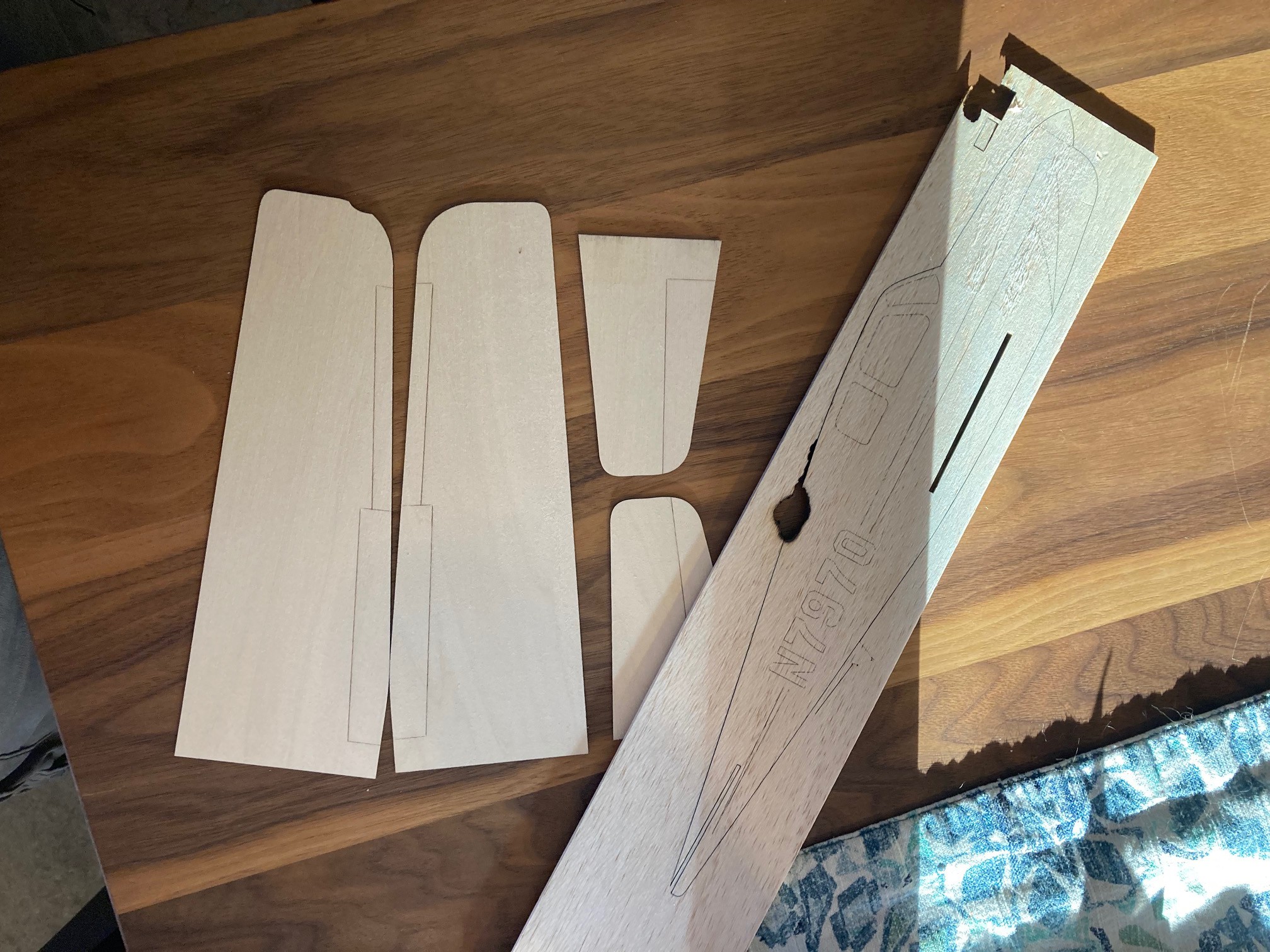
A few weeks ago I put up some plans for a balsa wood model airplane. Today I made a stab at cutting it out. The wings cut out great, I was able to easily mark the flap details and cut through the 1/16" wood in one pass at 80% power and 150 mm/min speed.
![]()
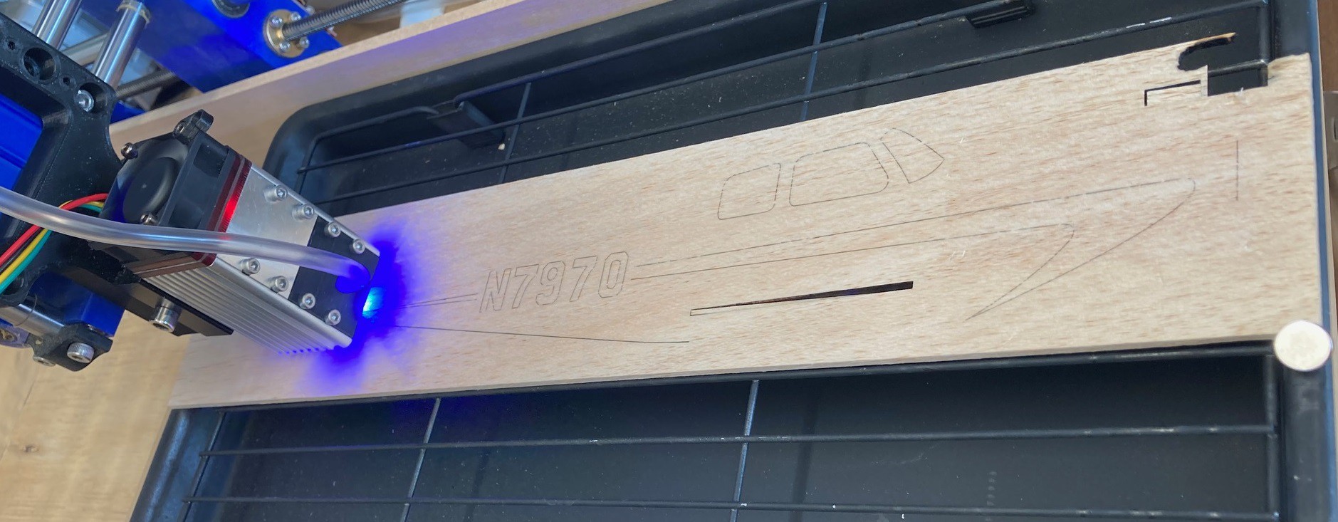
I also picked up a piece of 1/4" balsa wood for the body. This is a particularly solid piece of wood and I was only just able to cut through it at 50 mm/min at 80% power and 3 passes. This was so painfully slow that I did not end up finishing the cut (actually lightburn goofed up and lost its position... a tail for another day).
![]()
Finally I have a piece of 1/8" balsa wood that I also tried to use to make a body out of. This is a particularly pithy piece of wood, I could easily snap it without effort. No matter how fast I cut the wood would tend to catch on fire and burn out of control. I tried using extra air to keep the flames at bay but that only seemed to make it worse. I ended up trying to cut the piece out at 200 mm/min, 80% power and 2 passes. However the cut was a mess, with large portions of it either uncut or burnt excessively.
I need to get a new piece of 1/8" wood and this time I will pick the most dense piece I can find. Maybe that will cut better.
My plans have a small flaw in them, the slot for the wing in the main body is 4 mm to short. I will try to correct the plans once the plane is finally put together.
-
Focal length
07/19/2021 at 04:44 • 0 commentsI did a quick test setting the laser up with a 46 mm focal length and again with a 6 mm focal length and tried cutting a series of lines in pine at various z heights around the focal point. It was not a perfect test, the variation in the line height was very inconsistent with up to 40% changes in depth from line to line. However overall the 6 mm focal height was deeper on average than the 46 mm focal height.
![]()
I need to find a new test material that is more consistent from cut to cut. I have a piece of 1/4" balsa wood that may make a good target, it feels very uniform. The pine had strong rings in it that appeared to create alternating soft and hard spots in the wood.
Also I may have ended up setting the 46 mm focal length a bit low, at the end of all my runs the head was only 44 mm above the work surface. I'm not sure when it moved. The point is this is not a valid test, but it does not appear that a longer focal length has a huge impact on the cutting power.
-
Roto-Rooter
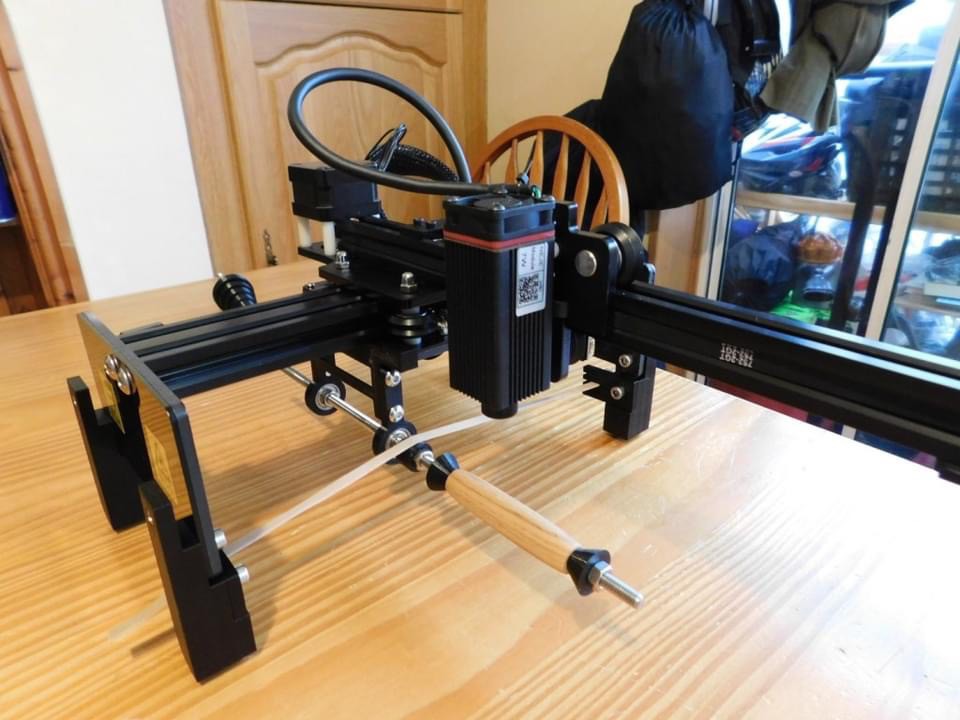
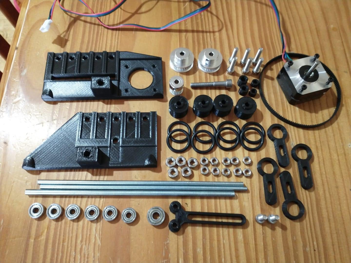
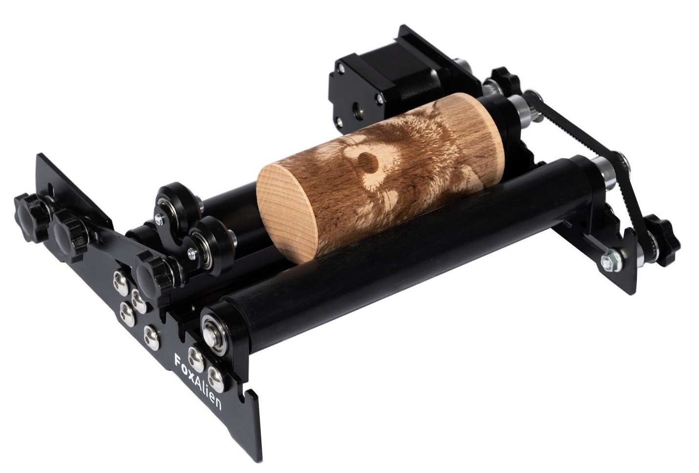
07/17/2021 at 05:12 • 0 commentsAs a follow-up to my last post, here are a few different 3D printed rotary attachments that where made by Crossgates Crafts. These are all designed for use with a diode laser system, but they are well engineered and have good examples of how to minimize costs without sacrificing quality.
![]()
The simplest solution does not even have a stepper motor, instead it relies on the motion of the X axis. By tying the rotary axis to the edge of the Y axis and using a rubber band to act as a belt, movement along the X axis makes the whole thing roll. This only uses two bearings, some threaded rod and a few pieces of random hardware.
The down side is you can only mount the material on one side, or in this case via a center hole.
![]()
![]()
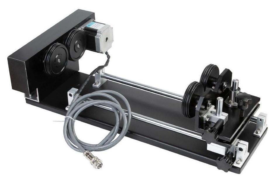
Next we have a roller setup, you can see how the use of different wheels can allow you to support very odd shaped parts. This requires a stepper motor, 6-7 bearings, a belt and gear set and various supporting hardware.
One of the downsides here is that the whole setup is very tall. In this case it is designed for an open framed laser rig that can have feet added to it to raise it up to any height, but for our setup this would be much too tall. You could make this shorter, but it will always eat up some vertical height.
![]()
![]()
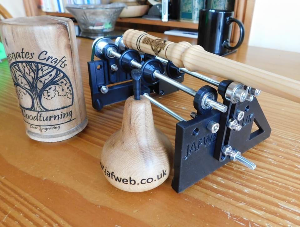
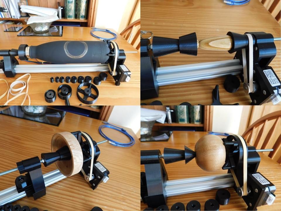
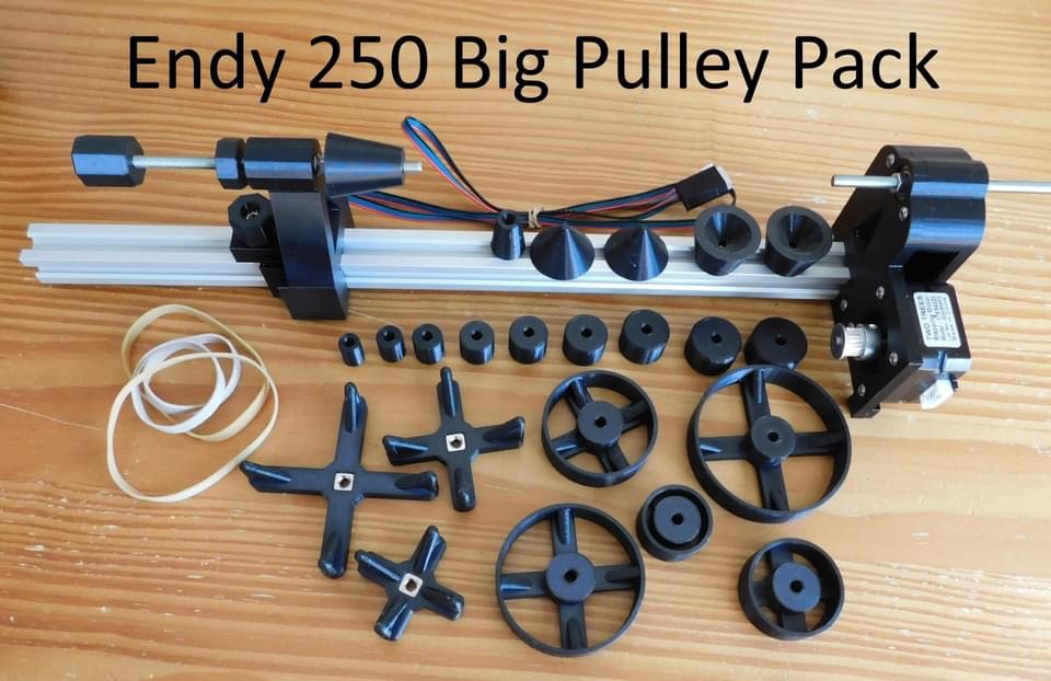
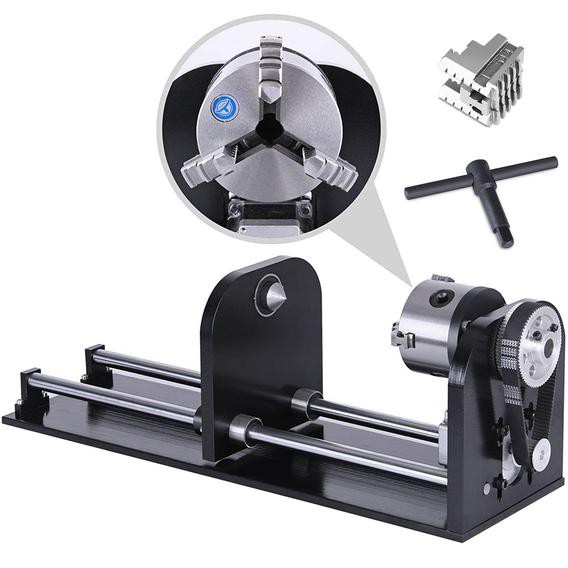
Finally we have a chuck style setup. This has the unique idea of using simple rubber bands and 3D printed pulleys rather than a proper toothed belt and pulley set. This saves money and simplifies the setup. it is using a stepper motor, 4 bearings, some form of base that allows the tail stock to slide back and forth and various supporting hardware.
Notice that this setup allows for different size pullies to be substituted in. The idea being that you pick a pully that closely matches the diameter of the part you are cutting, that way the rotary setup acts like a roller setup.
This also highlights the advantage of the chuck style setup. By changing out the spindle and quill (pointy part of the tail stock) you can mount almost any part to the setup.
-
Driven
07/15/2021 at 04:37 • 0 commentsI have eluded to it before but never talked about the different types of rotary axis we can implement. There are three choices, two of which are a better fit for our system.
![]()
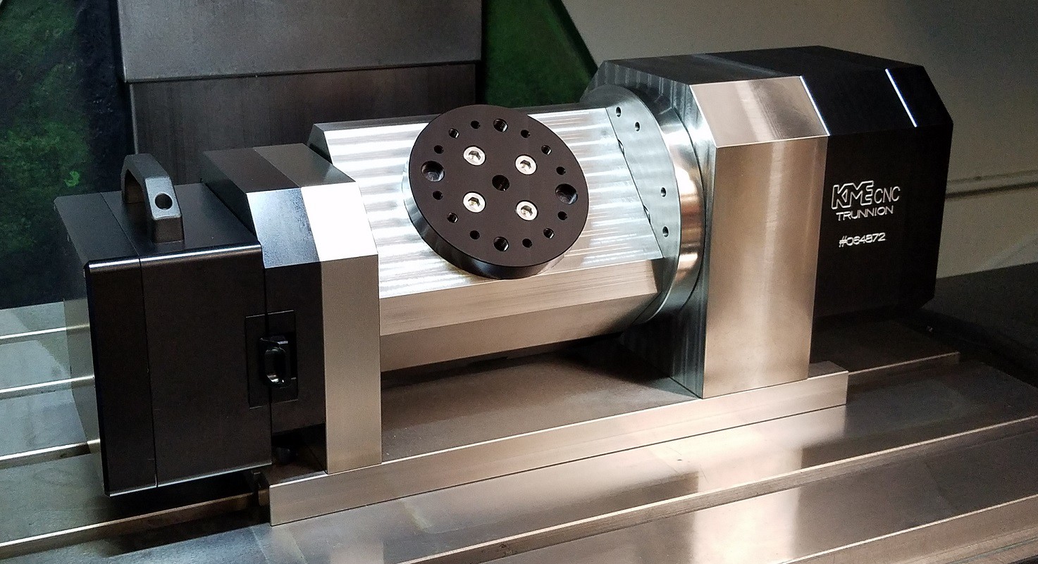
The first option is a 5 axis trunnion table. This is basically a rotary axis that can be tilted and the big advantage over a rotary axis is that you can cut pockets at most any angle to the base of the part. Think of machining the top end of a v8 engine block in one programming step.
The down side here is that it requires 5 stepper drivers at a minimum to work (6 if we want to keep using an auto squaring x axis and keep the y axis in play). The other issue is that it needs a lot more vertical working height than we have to give.
![]()
The next option is some sort of a roller system. These can be long rollers or individual wheels that can be positioned at key places under the part. If the part has some sort of taper to it you can add a second set of idler wheels to prop up the narrow end of the part on so the face is parallel to the laser or tool.
![]()
The upside here is simplicity and ease of setup, and in certain cases the ability to handle longer objects.
On the downside the part is only held in place by friction so a light weight part may need weights added to it to make it work, and there is always the chance of the part slipping so you are more or less restricted to raster images where the part only makes one single rotation while being etched. Also this is basically limited to laser etching since it is the only tool that does not touch the part.
This setup is driven by the circumference of the part. That is rotating the stepper by a fixed amount will always move the outer surface of the part a fixed amount, regardless of the diameter of the part. i.e. moving the motor 10 degrees may move the surface of the part 5 mm for a 10 or 80 mm diameter part.
![]()
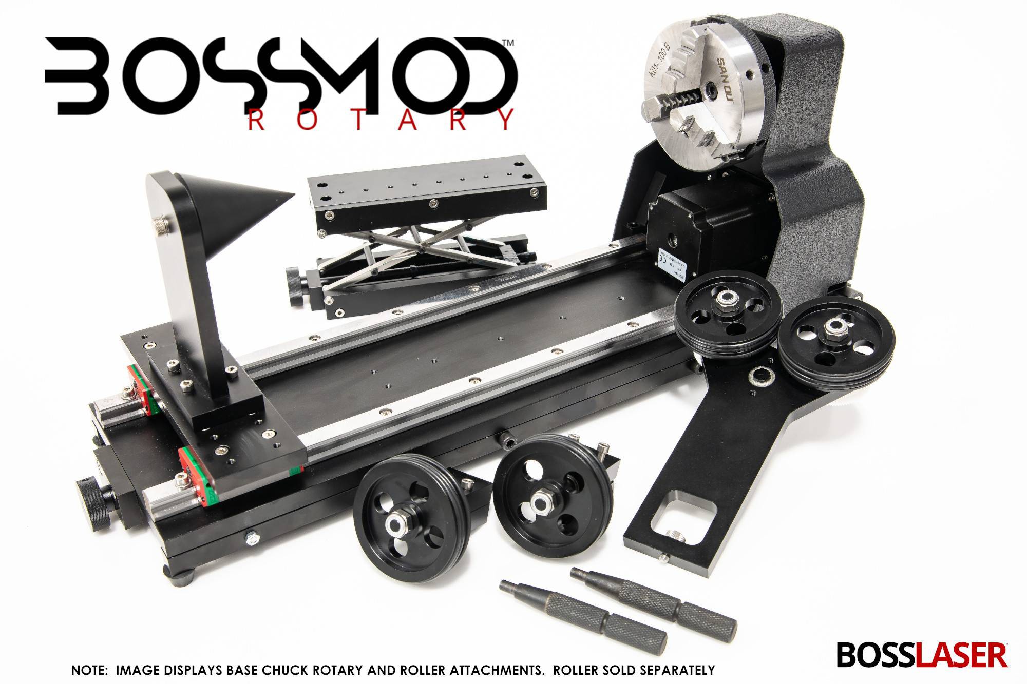
The last option is using a chuck or other hub with an optional tail stock to help support the part. The piece is clamped in the chuck or bolted directly to the hub in some fashion.
The upside here is that the part is very well clamped so it can't slip. That allows us to move the part back and forth with a high level of precision and it allows us to use various cutters to carve away the material in addition to using a laser.
On the downside it is more complicated to deal with tapered parts. You either need to tilt the chuck or tilt the whole mechanism. This is doable but it is not as simple as sliding some wheels around. Also if you want to cut really long parts you need some sort of additional support or you have to give up on the tail stock and only support the part from one end.
This setup is driven by angular position. That is rotating the stepper motor a certain amount will rotate the part through a set angle regardless of the diameter of the part i.e. rotating the stepper 10 degrees may rotate the part 1 degree for a 10 or 80 mm diameter part.
![]()
It is also possible to make a setup that combines both rollers and a chuck into the same jig.
I think for our needs a chuck type setup is the best. Rollers may be simpler to design but they can't be used with the mill and since we have such a small working z height we really need a setup that allows us to use the full vertical range.
MultiBot CNC v2
A low cost 3D printed CNC that can be built with minimal tools yet is capable of great things.